Page 81 of 106

Periodic maintenance an d a djustment
6-31
6
EAU59871
Replacin g the fusesThe main fuse and the fuse boxes,
which contain the fuses for the individ-
ual circuits, are located under the rider
seat. (See page 3-19.)TIPTo access the main fuse, remove the
starter relay cover as shown.
MT07 MT07A
If a fuse is blown, replace it as follows.
1. Turn the key to “OFF” and turn off the electrical circuit in question.
2. Remove the blown fuse, and then install a new fuse of the specified
amperage. WARNING! Do not
1. Starter relay cover
2. Fuse box
3. Spare main fuse
4. Main fuse
2
3
4
1
1. Ignition fuse
2. Signaling system fuse
3. Headlight fuse
4. Fuel injection system fuse
5. Backup fuse (for clock and immobilizer sys-
tem)
6. Radiator fan motor fuse
7. Parking lighting fuse
8. Auxiliary fuse
9. Spare fuse
7
8
1
2
3
4
5
699
1. Ignition fuse
2. Signaling system fuse
3. Headlight fuse
4. Fuel injection system fuse
5. Backup fuse (for clock and immobilizer sys- tem)
6. Radiator fan motor fuse
7. ABS solenoid fuse
8. ABS motor fuse
9. Parking lighting fuse
10.Auxiliary fuse
11.ABS control unit fuse
12.Spare fuse
7
8
9
10
11
1
2
3
4
5
61212
U1WSE3E0.book Page 31 Monday, June 8, 2015 10:12 AM
Page 82 of 106

Periodic maintenance an d a djustment
6-32
6 use a fuse of a hi
gher ampera ge
ratin g than recommen ded to
avoi d causin g extensive d am-
a g e to the electrical system an d
possi bly a fire.
[EWA15132]
3. Turn the key to “ON” and turn on
the electrical circuit in question to
check if the device operates.
4. If the fuse immediately blows again, have a Yamaha dealer
check the electrical system.
EAU59881
Replacin g the hea dlig ht bul bThis model is equipped with a halogen
bulb headlight. If the headlight bulb
burns out, replace it as follows.NOTICE
ECA10651
Take care not to damag e the follow-
in g parts:
Hea dlig ht bul b
Do not touch the glass part of
the hea dlig ht bul b to keep it free
from oil, otherwise the transpar-
ency of the glass, the luminosity
of the b ulb, an d the b ulb life will
b e ad versely affecte d. Thor-
ou ghly clean off any d irt and fin-
g erprints on the hea dlig ht bul b
usin g a cloth moistene d with al-
cohol or thinner.
Hea dlig ht lens
Do not affix any type of tinte d
film or stickers to the hea dlig ht
lens.
Do not use a hea dlig ht bul b of a
wattag e higher than specifie d.
Specifie d fuses:
Main fuse: 30.0 A
Auxiliary fuse:
2.0 A
Headlight fuse: 15.0 A
Signaling system fuse: 10.0 A
Ignition fuse:
10.0 A
Parking lighting fuse: 7.5 A
Radiator fan motor fuse: 10.0 A
ABS motor fuse:
30.0 A (MT07A)
ABS solenoid fuse: 20.0 A (MT07A)
Fuel injection system fuse: 10.0 A
ABS control unit fuse:
7.5 A (MT07A)
Backup fuse: 7.5 A
U1WSE3E0.book Page 32 Monday, June 8, 2015 10:12 AM
Page 83 of 106
Periodic maintenance an d a djustment
6-33
6
1. Remove the headlight unit by re-
moving the bolt and washer on
each side. 2. Disconnect the headlight coupler,
and then remove the headlight
bulb cover.
3. Unhook the headlight bulb holder, then remove the burnt-out bulb. 4. Place a new headlight bulb into
position, then secure it with the
bulb holder.
5. Install the headlight bulb cover, then connect the coupler.
6. Install the headlight unit as shown, and then install the washer and
bolt on each side.
1. Do not touch the glass part of the bulb.
1. Bolt and washer1
1. Bolt and washer
1. Headlight coupler
2. Headlight bulb cover
11
2
1. Headlight bulb holder
2. Headlight bulb
2
1
U1WSE3E0.book Page 33 Monday, June 8, 2015 10:12 AM
Page 84 of 106
Periodic maintenance an d a djustment
6-34
6 7. Have a Yamaha dealer adjust the
headlight beam if necessary.
EAU46405
Replacin g the auxiliary li ght
b ul bIf the auxiliary light bulb burns out, re-
place it as follows.
1. Remove the headlight unit. (See page 6-32.)
2. Remove the auxiliary light bulb socket (together with the bulb) by
turning it counterclockwise.
3. Remove the burnt-out bulb by pulling it out of the socket. 4. Insert a new bulb into the socket.
5. Install the socket (together with
the bulb) by turning it clockwise.
6. Install the headlight unit.1. Auxiliary light bulb socket
1
1. Auxiliary light bulb
1
U1WSE3E0.book Page 34 Monday, June 8, 2015 10:12 AM
Page 85 of 106
Periodic maintenance an d a djustment
6-35
6
EAU24182
Tail/b rake li ghtThis model is equipped with an LED-
type tail/brake light.
If the tail/brake light does not come on,
have a Yamaha dealer check it.
EAU24205
Replacin g a turn sig nal light
b ul b1. Remove the turn signal light lens
by removing the screw.
2. Remove the burnt-out bulb by pushing it in and turning it coun-
terclockwise. 3. Insert a new bulb into the socket,
push it in, and then turn it clock-
wise until it stops.
4. Install the lens by installing the screw. NOTICE: Do not over-
ti ghten the screw, otherwise the
lens may break.
[ECA11192]
1. Turn signal light lens
2. Screw
1
2
1. Turn signal light bulb
1
U1WSE3E0.book Page 35 Monday, June 8, 2015 10:12 AM
Page 86 of 106

Periodic maintenance an d a djustment
6-36
6
EAU59890
Replacin g the license plate
li g ht bul b1. Remove the license plate light unit
by removing the nuts, washers
and collars, and then remove the
license plate light bulb socket (to-
gether with the bulb) by pulling it
out.
2. Remove the burnt-out bulb by pulling it out. 3. Insert a new bulb into the socket.
4. Install the socket (together with
the bulb) by pushing it in, and then
install the license plate light unit by
installing the collars, washers and
nuts.
EAU24351
Supportin g the motorcycleSince this model is not equipped with a
centerstand, follow these precautions
when removing the front and rear
wheel or performing other mainte-
nance requiring the motorcycle to
stand upright. Check that the motorcy-
cle is in a stable and level position be-
fore starting any maintenance. A
strong wooden box can be placed un-
der the engine for added stability.
To service the front wheel
1. Stabilize the rear of the motorcy- cle by using a motorcycle stand
or, if an additional motorcycle
stand is not available, by placing a
jack under the frame in front of the
rear wheel.
2. Raise the front wheel off the ground by using a motorcycle
stand.
To service the rear wheel
Raise the rear wheel off the ground by
using a motorcycle stand or, if a motor-
cycle stand is not available, by placing
1. License plate light unit
2. Collar
3. Washer
4. Nut
5. License plate light bulb socket
1
22
53
4
3
4
1. License plate light bulb
1
U1WSE3E0.book Page 36 Monday, June 8, 2015 10:12 AM
Page 87 of 106
Periodic maintenance an d a djustment
6-37
6
a jack either under each side of the
frame in front of the rear wheel or under
each side of the swingarm.
EAU44792
Front wheel (for non-ABS
mo
dels)
WARNING
EWA14841
For the ABS mo del, have a Yamaha
d ealer remove an d install the wheel.
EAU59931
To remove the front wheel
WARNING
EWA10822
To avoi d injury, securely support the
vehicle so there is no dan ger of it
fallin g over.1. Loosen the front wheel axle pinch
bolt, then the wheel axle and the
brake caliper bolts. 2. Lift the front wheel off the ground
according to the procedure in the
previous section “Supporting the
motorcycle”.
3. Remove the brake hose holder on the left side by removing the bolt.
1. Front wheel axle pinch bolt
2. Wheel axle
3. Brake caliper bolt23
1
U1WSE3E0.book Page 37 Monday, June 8, 2015 10:12 AM
Page 88 of 106

Periodic maintenance an d a djustment
6-38
6
4. Remove the brake caliper on eachside by removing the bolts.
NOTICE: Do not apply the b rake
after the brake calipers have
b een removed , otherwise the
b rake pa ds will be forced shut.
[ECA11052]
5. Pull the wheel axle out, and then
remove the wheel.
To install the front wheel 1. Lift the wheel up between the fork legs.
2. Insert the wheel axle from the right side. 3. Lower the front wheel so that it is
on the ground, and then put the
sidestand down.
4. Install the brake calipers by install- ing the bolts.
TIPMake sure that there is enough space
between the brake pads before install-
ing the brake calipers onto the brake
discs.5. Install the brake hose holder by in-stalling the bolt.
6. Tighten the brake caliper bolts and the brake hose holder bolt to the
specified torques.
7. Tighten the wheel axle, and then the wheel axle pinch bolt to the
specified torques. 8. Push down hard on the handlebar
several times to check for proper
fork operation.
1. Brake hose holder
2. Bolt
3. Brake caliper
4. Brake caliper bolt4
321
Tightenin g torques:
Brake caliper bolt: 40 Nm (4.0 m·kgf, 29 ft·lbf)
Brake hose holder bolt:
7 Nm (0.7 m·kgf, 5.1 ft·lbf)
Tightenin g torques:
Wheel axle:
65 Nm (6.5 m·kgf, 47 ft·lbf)
Front wheel axle pinch bolt:
23 Nm (2.3 m·kgf, 17 ft·lbf)
U1WSE3E0.book Page 38 Monday, June 8, 2015 10:12 AM
 1
1 2
2 3
3 4
4 5
5 6
6 7
7 8
8 9
9 10
10 11
11 12
12 13
13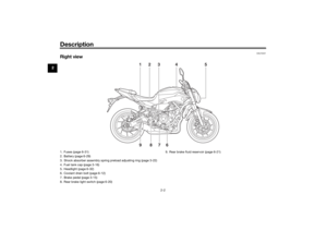 14
14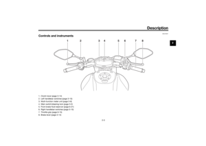 15
15 16
16 17
17 18
18 19
19 20
20 21
21 22
22 23
23 24
24 25
25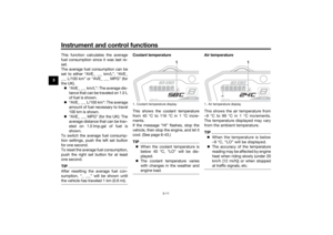 26
26 27
27 28
28 29
29 30
30 31
31 32
32 33
33 34
34 35
35 36
36 37
37 38
38 39
39 40
40 41
41 42
42 43
43 44
44 45
45 46
46 47
47 48
48 49
49 50
50 51
51 52
52 53
53 54
54 55
55 56
56 57
57 58
58 59
59 60
60 61
61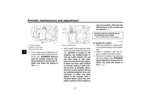 62
62 63
63 64
64 65
65 66
66 67
67 68
68 69
69 70
70 71
71 72
72 73
73 74
74 75
75 76
76 77
77 78
78 79
79 80
80 81
81 82
82 83
83 84
84 85
85 86
86 87
87 88
88 89
89 90
90 91
91 92
92 93
93 94
94 95
95 96
96 97
97 98
98 99
99 100
100 101
101 102
102 103
103 104
104 105
105


WARNI")