Page 73 of 96

This model is equipped with a VRLA
(Valve Regulated Lead Acid) battery.
There")
Periodic maintenance an d a djustment
6-28
6
EAU62521
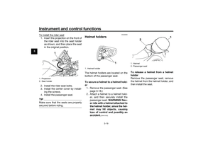
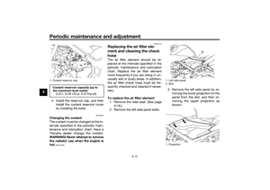
BatteryThe battery is located under the rider
seat. (See page 3-18.)
This model is equipped with a VRLA
(Valve Regulated Lead Acid) battery.
There is no need to check the electro-
lyte or to add distilled water. However,
the battery lead connections need to
be checked and, if necessary, tight-
ened.
WARNING
EWA10761
Electrolyte is poisonous an d
d an gerous since it contains sul-
furic aci d, which causes severe b
urns. Avoi d any contact with
skin, eyes or clothin g an d al-
ways shiel d your eyes when
workin g near b atteries. In case
of contact, ad minister the fol-
lowin g FIRST AID.
EXTERNAL: Flush with plenty of water.
INTERNAL: Drink lar ge quan-
tities of water or milk an d im-
me diately call a physician.
EYES: Flush with water for 15 minutes an d seek prompt
me dical attention.
Batteries pro duce explosive hy-
d ro gen gas. Therefore, keep
sparks, flames, ci garettes, etc.,
away from the b attery and pro-
vi de sufficient ventilation when
char gin g it in an enclose d
space.
KEEP THIS AND ALL BATTER-
IES OUT OF THE REACH OF
CHILDREN.
NOTICE
ECA10621
Never attempt to remove the b attery
cell seals, as this woul d permanently
d amag e the b attery.To char ge the b attery
Have a Yamaha dealer charge the bat-
tery as soon as possible if it seems to
have discharged. Keep in mind that the
battery tends to discharge more quick-
ly if the vehicle is equipped with op-
tional electrical accessories.NOTICE
ECA16522
To char ge a VRLA (Valve Re gulate d
Lea d Aci d) battery, a special (con-
stant-volta ge) battery char ger is re-
quire d. Usin g a conventional b attery
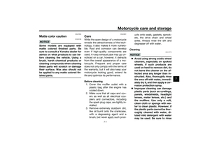
char ger will d amage the battery.To store the battery
1. If the vehicle will not be used for more than one month, remove the
battery, fully charge it, and then
place it in a cool, dry place.
NOTICE: When removin g the
b attery, be sure the key is
1. Battery
2. Negative battery lead (black)
3. Positive battery lead (red)
1
2
3
UB08E1E0.book Page 28 Friday, October 2, 2015 9:33 AM
Page 74 of 96
![YAMAHA MT-03 2016 Owners Manual Periodic maintenance an d a djustment
6-29
6 turne
d to “ ”, then disconnect
the ne gative lea d b efore discon-
nectin g the positive lea d.
[ECA17712]
2. If the battery will be stored for
mor](/manual-img/51/50740/w960_50740-73.png "YAMAHA MT-03 2016 Owners Manual Periodic maintenance an d a djustment
6-29
6 turne
d to “ ”, then disconnect
the ne gative lea d b efore discon-
nectin g the positive lea d.
[ECA17712]
2. If the battery will be stored for
mor")
Periodic maintenance an d a djustment
6-29
6 turne
d to “ ”, then disconnect
the ne gative lea d b efore discon-
nectin g the positive lea d.
[ECA17712]
2. If the battery will be stored for
more than two months, check it at
least once a month and fully
charge it if necessary.
3. Fully charge the battery before in- stallation. NOTICE: When install-
in g the b attery, be sure the key
is turne d to “ ”, then connect
the positive lea d before con-
nectin g the ne gative lea d.
[ECA17722]
4. After installation, make sure that
the battery leads are properly con-
nected to the battery terminals.NOTICE
ECA16531
Always keep the b attery charged .
Storin g a d ischar ged battery can
cause permanent battery dama ge.
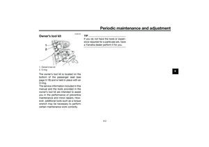
EAUN0820
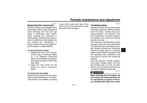
Replacin g the fusesThe main fuse is located under the
passenger seat. (See page 3-18.)
To access the main fuse, proceed as
follows.
1. Remove the passenger seat. (See page 3-18.)
2. Remove the tray by removing the quick fasteners.
3. Pull back the starter relay cover, and then disconnect the starter re-
lay coupler as shown. 4. Connect the starter relay coupler,
and then slide the cover to its orig-
inal position.
5. Place the tray in its original posi- tion, and then install the quick fas-
teners.
6. Install the passenger seat.
Fuse box 1 is located behind the center
cover. (See page 3-18.)1. Quick fastener
2. Tray
2 1
1. Starter relay cover
2. Starter relay coupler
3. Main fuse
4. Spare main fuse
1
2
34
UB08E1E0.book Page 29 Friday, October 2, 2015 9:33 AM
Page 75 of 96

Fuse box 2
If a fuse is blown, replace it as follows. 1. Turn the key to “ ” a")
Periodic maintenance an d a djustment
6-30
6
Fuse
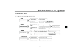
box 1 Fuse box 2 is located under the rider
seat. (See page 3-18.)
Fuse box 2
If a fuse is blown, replace it as follows. 1. Turn the key to “ ” and turn off
the electrical circuit in question.
2. Remove the blown fuse, and then install a new fuse of the specified
amperage. WARNING! Do not
use a fuse of a hi gher ampera ge
ratin g than recommen ded to
avoi d causin g extensive dam-
a g e to the electrical system an d
possi bly a fire.
[EWA15132]
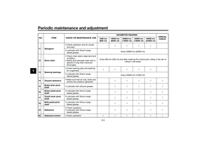
1. Fuse box 1
1. Ignition fuse
2. Signaling system fuse
3. ABS control unit fuse
4. Backup fuse (for clock)
5. Headlight fuse
6. Radiator fan motor fuse
7. Spare fuse
17
123
56
4
1. Fuse box 2
1. Spare fuse
2. ABS solenoid fuse
3. ABS motor fuse
1
1
2
3
Specified fuses:
Main fuse: 30.0 A
Headlight fuse:
15.0 A
Signaling system fuse: 7.5 A
Ignition fuse: 15.0 A
Radiator fan motor fuse:
7.5 A
ABS motor fuse: 30.0 A
ABS solenoid fuse: 15.0 A
ABS control unit fuse:
7.5 A
Backup fuse: 7.5 A
UB08E1E0.book Page 30 Friday, October 2, 2015 9:33 AM
Page 76 of 96
Periodic maintenance an d a djustment
6-31
6 3. Turn the key to “ ” and turn on
the electrical circuit in question to
check if the device operates.
4. If the fuse immediately blows again, have a Yamaha dealer
check the electrical system.
EAU68470
Replacin g the hea dlig ht bul bThis model is equipped with halogen
bulb headlight. If a headlight bulb
burns out, have a Yamaha dealer re-
place it and, if necessary, adjust the
headlight beam.NOTICE
ECA17871
Hea dlig ht lens:
Do not affix any type of tinte d film or
stickers to the hea dlig ht lens.
Do not use a hea dlig ht bul b of a
wattag e higher than specifie d.
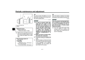
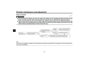
EAU44941
Auxiliary li ghtThis model is equipped with an LED-
type auxiliary light.
If the auxiliary light does not come on,
have a Yamaha dealer check it.1. Auxiliary light
1
1
UB08E1E0.book Page 31 Friday, October 2, 2015 9:33 AM
Page 77 of 96
Periodic maintenance an d a djustment
6-32
6
EAU24182
Tail/b rake li ghtThis model is equipped with an LED-
type tail/brake light.
If the tail/brake light does not come on,
have a Yamaha dealer check it.
EAU62590
Replacin g a turn sig nal light
b ul b1. Remove the turn signal light lens
by removing the screw.
2. Remove the turn signal light bulb socket (together with the bulb) by
turning it counterclockwise. 3. Remove the burnt-out bulb by
pulling it out.
4. Insert a new bulb into the socket.
5. Install the socket (together with the bulb) by turning it clockwise.
6. Install the turn signal light lens by installing the screw. NOTICE: Do
not overti ghten the screw, oth-
erwise the lens may break.
[ECA11192]
1. Turn signal light lens
2. Screw
1
2
1. Turn signal light bulb socket
1
UB08E1E0.book Page 32 Friday, October 2, 2015 9:33 AM
Page 78 of 96
Periodic maintenance an d a djustment
6-33
6
EAU62670
Replacin g the license plate
li g ht bul b1. Remove the mudguard by remov-
ing the quick fasteners.
2. Remove the rear fender lower panel by removing the bolts and
screws. 3. Remove the license plate light
bulb socket (together with the
bulb) by pulling it out.
4. Remove the burnt-out bulb by pulling it out. 5. Insert a new bulb into the socket.
6. Install the socket (together with
the bulb) by pushing it in.
7. Install the rear fender lower panel by installing the bolts and screws.
8. Install the mudguard by installing the quick fasteners.1. Mudguard
2. Quick fastener
1
2
1. Bolt
2. Screw
3. Rear fender lower panel
1. License plate light bulb
2. License plate light bulb socket
3
2
1
2
2
121
UB08E1E0.book Page 33 Friday, October 2, 2015 9:33 AM
Page 79 of 96

Periodic maintenance an d a djustment
6-34
6
EAU24351
Supportin g the motorcycleSince this model is not equipped with a
centerstand, follow these precautions
when removing the front and rear
wheel or performing other mainte-
nance requiring the motorcycle to
stand upright. Check that the motorcy-
cle is in a stable and level position be-
fore starting any maintenance. A
strong wooden box can be placed un-
der the engine for added stability.
To service the front wheel
1. Stabilize the rear of the motorcy- cle by using a motorcycle stand
or, if an additional motorcycle
stand is not available, by placing a
jack under the frame in front of the
rear wheel.
2. Raise the front wheel off the ground by using a motorcycle
stand.
To service the rear wheel
Raise the rear wheel off the ground by
using a motorcycle stand or, if a motor-
cycle stand is not available, by placing a jack either under each side of the
frame in front of the rear wheel or under
each side of the swingarm.
EAU25872
Trou
bleshootin gAlthough Yamaha motorcycles receive
a thorough inspection before shipment
from the factory, trouble may occur
during operation. Any problem in the
fuel, compression, or ignition systems,
for example, can cause poor starting
and loss of power.
The following troubleshooting charts
represent quick and easy procedures
for checking these vital systems your-
self. However, should your motorcycle
require any repair, take it to a Yamaha
dealer, whose skilled technicians have
the necessary tools, experience, and
know-how to service the motorcycle
properly.
Use only genuine Yamaha replace-
ment parts. Imitation parts may look
like Yamaha parts, but they are often
inferior, have a shorter service life and
can lead to expensive repair bills.
WARNING
EWA15142
When checkin g the fuel system, d o
not smoke, an d make sure there are
no open flames or sparks in the ar-
ea, inclu din g pilot li ghts from water
UB08E1E0.book Page 34 Friday, October 2, 2015 9:33 AM
Page 80 of 96
Periodic maintenance an d a djustment
6-35
6 heaters or furnaces. Gasoline or
g
asoline vapors can i gnite or ex-
plo de, causin g severe injury or prop-
erty damag e.
UB08E1E0.book Page 35 Friday, October 2, 2015 9:33 AM