Page 49 of 120
Instrument and control functions
3-35
3
EAU40254
Stora ge compartments
This vehicle is equipped with two stor-
age compartments.
Storage compartment A is located un-
der the rider seat. (See page 3-31.)
Storage compartment B is located un-
der the passenger seat. (See page
3-31.)
When storing documents or other
items in a storage compartment, be
sure to wrap them in a plastic bag so
that they will not get wet. When wash-
ing the vehicle, be careful not to let any
water enter a storage compartment.
WARNING
EWA14421
Do not exceed the load limit of 1
k g (2 l b) for stora ge compart-
ment A.
Do not exceed the load limit of 3
k g (7 l b) for stora ge compart-
ment B.
Do not exceed the maximum
loa d of 215 k g (474 l b) for the ve-
hicle.
1. Storage compartment A
1. Storage compartment B
1
1
UB88E0E0.book Page 35 Friday, October 16, 2015 11:59 AM
Page 50 of 120
Instrument and control functions
3-36
3
EAU39482
Accessory box
The accessory box is located beside
the meter panel.
To open the accessory box
1. Insert the key into the main switch, and then turn it to “ON”.
2. Push the accessory box button, and then open the accessory box
lid.
3. Turn the key to “OFF” to preserve the battery.
To close the accessory box
1. Fold the accessory box lid down.
2. Remove the key.
NOTICE
ECA11802
Do not place heat-sensitive items in
the accessory box. The accessory
b ox can get hot when the en gine is
running or the vehicle is in d irect
sunli ght.
WARNING
EWA11422
Do not exceed the load limit of
0.3 k g (0.66 l b) for the accessory
b ox.
Do not exceed the maximum
loa d of 215 k g (474 l b) for the ve-
hicle.
1. Accessory box lid
2. Accessory box
3. Accessory box button
1
23
UB88E0E0.book Page 36 Friday, October 16, 2015 11:59 AM
Page 51 of 120
Instrument and control functions
3-37
3
EAU39612
A djustin g the hea dlig ht beams
The headlight beam adjusting knobs
are used to raise or lower the height of
the headlight beams. It may be neces-
sary to adjust the headlight beams to
increase visibility and help prevent
blinding oncoming drivers when carry-
ing more or less load than usual. Obey
local laws and regulations when ad-
justing the headlights.
To raise the headlight beams, turn the
knobs in direction (a). To lower the
headlight beams, turn the knobs in di-
rection (b).
EAU39642
Han dle bar position
The handlebars can be adjusted to one
of three positions to suit the rider’s
preference. Have a Yamaha dealer ad-
just the position of the handlebars.
1. Headlight beam adjusting knob
11
(b)(a)(b)(a)
1. Handlebar
11
UB88E0E0.book Page 37 Friday, October 16, 2015 11:59 AM
Page 52 of 120
 for added ventilation to
suit the riding conditions.
To ope")
Instrument and control functions
3-38
3
EAU54151
Openin g an d closin g the cowl-
in g vents
The cowling vents can be opened 20
mm (0.79 in) for added ventilation to
suit the riding conditions.
To open a cowlin g vent
1. Remove the quick fastener.
2. Slide the cowling vent panel for- ward to unhook its projections
from the lower slots, and then pull
the panel off.
3. Insert the projections into the up- per slots, and then slide the panel
backward. 4. Install the quick fastener.
To close a cowlin g vent
1. Remove the quick fastener.
2. Slide the cowling vent panel for- ward to unhook its projections
from the upper slots, and then pull
the panel off.
3. Insert the projections into the low- er slots, and then slide the panel
backward.
1. Closed position
2. Open position
1. Cowling vent panel
2. Lower slot
3. Quick fastener
12
3
1
2
1. Projection
2. Upper slot
3. Quick fastener
1. Cowling vent panel
2. Upper slot
3. Quick fastener
1
3
2
3
1
2
UB88E0E0.book Page 38 Friday, October 16, 2015 11:59 AM
Page 53 of 120
Instrument and control functions
3-39
3
4. Install the quick fastener.
TIP
Make sure that the cowling vent panels
are properly installed before riding.
EAU39672
Rear view mirrors
The rear view mirrors of this vehicle
can be folded forward or backward for
parking in narrow spaces. Fold the mir-
rors back to their original position be-
fore riding.
WARNING
EWA14372
Be sure to fol d the rear view mirrors
b ack to their ori ginal position b efore
ri din g.
1. Projection
2. Lower slot
3. Quick fastener
13
2
1. Riding position
2. Parking position
2
2
1
2 2
1
UB88E0E0.book Page 39 Friday, October 16, 2015 11:59 AM
Page 54 of 120

Instrument and control functions
3-40
3
EAU54141
A djustin g the front fork
WARNING
EWA14671
Always a djust the spring preload on
b oth fork leg s equally, otherwise
poor han dlin g an d loss of sta bility
may result.
Each front fork leg is equipped with a
spring preload adjusting bolt. The right
front fork leg is equipped with a re-
bound damping force adjusting knob
and compression damping force ad-
justing screw.
NOTICE
ECA10102
To avoi d d amag ing the mechanism,
d o not attempt to turn b eyond the
maximum or minimum settin gs.
Sprin g preloa d
To increase the spring preload and
thereby harden the suspension, turn
the adjusting bolt on each fork leg in di-
rection (a). To decrease the spring pre-
load and thereby soften the
suspension, turn the adjusting bolt on
each fork leg in direction (b).
The spring preload setting is deter-
mined by measuring distance A,
shown in the illustration. The shorter distance A is, the higher the spring pre-
load; the longer distance A is, the lower
the spring preload.
Re
boun d d ampin g force
The rebound damping force is adjust-
ed on the right front fork leg only.
To increase the rebound damping
force and thereby harden the rebound
damping, turn the adjusting knob in di-
rection (a). To decrease the rebound
damping force and thereby soften the
rebound damping, turn the adjusting
knob in direction (b).
1. Spring preload adjusting bolt
(a)(b)
11
(a)(b)
1. Distance A
Sprin g preloa d settin g:
Minimum (soft): Distance A = 20.0 mm (0.79 in)
Standard: Distance A = 15.0 mm (0.59 in)
Maximum (hard):
Distance A = 5.0 mm (0.20 in)
1. Rebound damping force adjusting knob
1
(a)(b)
1
UB88E0E0.book Page 40 Friday, October 16, 2015 11:59 AM
Page 55 of 120

Instrument and control functions
3-41
3
Compression
dampin g force
The compression damping force is ad-
justed on the right front fork leg only.
To increase the compression damping
force and thereby harden the com-
pression damping, turn the adjusting
screw in direction (a). To decrease the
compression damping force and there-
by soften the compression damping,
turn the adjusting screw in direction (b).
TIP
Although the total number of clicks of a
damping force adjusting mechanism
may not exactly match the above
specifications due to small differences
in production, the actual number of
clicks always represents the entire ad-
justing range. To obtain a precise ad-
justment, it would be advisable to
check the number of clicks of each
damping force adjusting mechanism
and to modify the specifications as
necessary.
Re boun d d ampin g settin g:
Minimum (soft): 22 click(s) in direction (b)*
Standard:
12 click(s) in direction (b)*
Maximum (hard): 1 click(s) in direction (b)*
* With the adjusting knob fully turned in direction (a)
1. Compression damping force adjusting
screw
Compression dampin g settin g:
Minimum (soft):
32 click(s) in direction (b)*
Standard: 11 click(s) in direction (b)*
Maximum (hard): 1 click(s) in direction (b)*
* With the adjusting screw fully
turned in direction (a)
UB88E0E0.book Page 41 Friday, October 16, 2015 11:59 AM
Page 56 of 120

Instrument and control functions
3-42
3
EAU14917
A djustin g the shock a bsorb er
assemb ly
This shock absorber assembly is
equipped with a spring preload adjust-
ing lever and a rebound damping force
adjusting knob.
NOTICE
ECA16571
To avoid d amag ing the mechanism,
d o not attempt to move b eyond the
maximum or minimum settin gs.
Sprin g preloa d
For riding solo, move the spring pre-
load adjusting lever in direction (a). For
riding with a passenger, move the
spring preload adjusting lever in direc-
tion (b).
Re boun d d ampin g force
To increase the rebound damping
force and thereby harden the rebound
damping, turn the adjusting knob in di-
rection (a). To decrease the rebound
damping force and thereby soften the
rebound damping, turn the adjusting
knob in direction (b).
TIP
To obtain a precise adjustment, it is
advisable to check the actual total
number of clicks or turns of the damp-
ing force adjusting mechanism. This
adjustment range may not exactly
match the specifications listed due to
small differences in production.
WARNING
EWA10222
This shock ab sorber assem bly con-
tains hi ghly pressurize d nitro gen
g as. Read and un derstan d the fol-
lowin g information before han dlin g
the shock a bsor ber assem bly.
Do not tamper with or attempt
to open the cylind er assembly.
Do not su bject the shock a b-
sor ber assem bly to an open
flame or other hi gh heat source.
1. Spring preload adjusting lever
1
(b)
(a)
1. Rebound damping force adjusting knob
Re boun d d ampin g settin g:
Minimum (soft): 20 click(s) in direction (b)*
Standard: 12 click(s) in direction (b)*
Maximum (hard):
1 click(s) in direction (b)*
* With the adjusting knob fully turned in direction (a)
UB88E0E0.book Page 42 Friday, October 16, 2015 11:59 AM
 1
1 2
2 3
3 4
4 5
5 6
6 7
7 8
8 9
9 10
10 11
11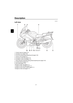 12
12 13
13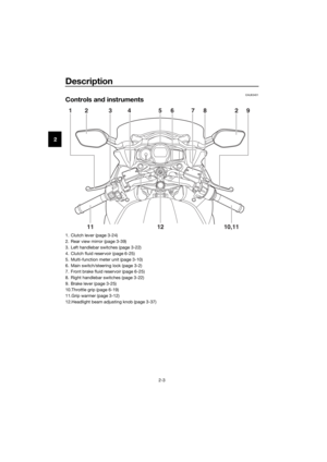 14
14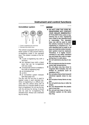 15
15 16
16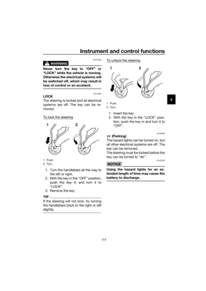 17
17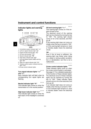 18
18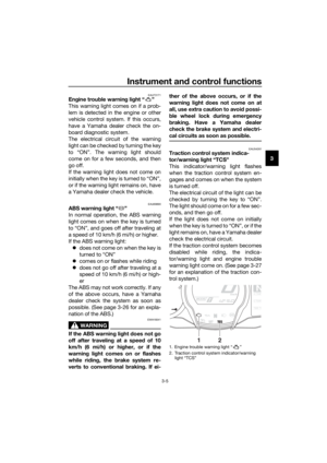 19
19 20
20 21
21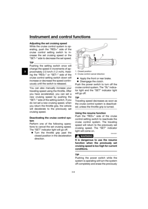 22
22 23
23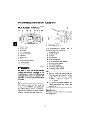 24
24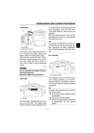 25
25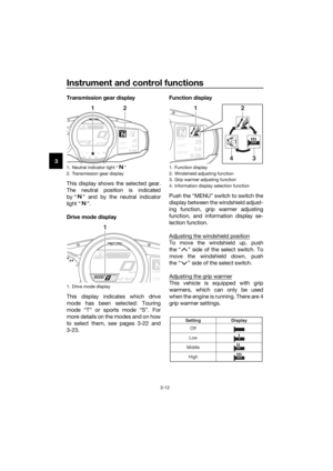 26
26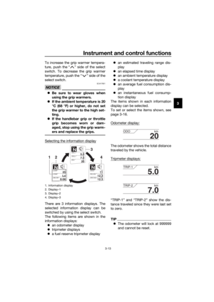 27
27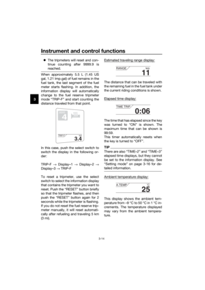 28
28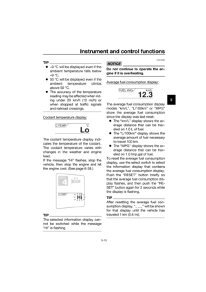 29
29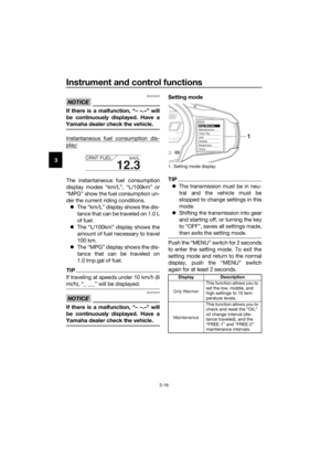 30
30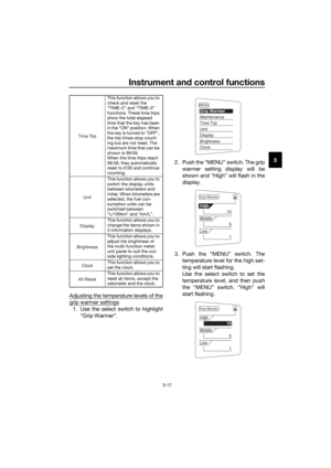 31
31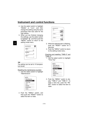 32
32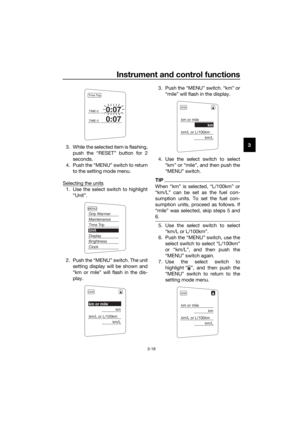 33
33 34
34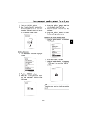 35
35 36
36 37
37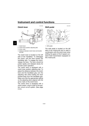 38
38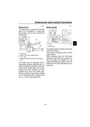 39
39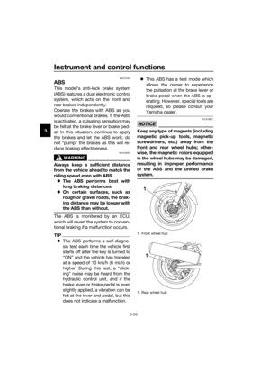 40
40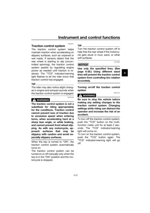 41
41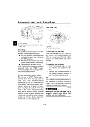 42
42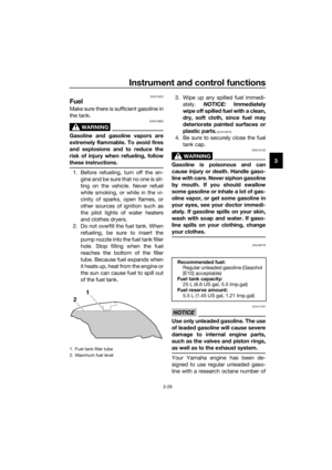 43
43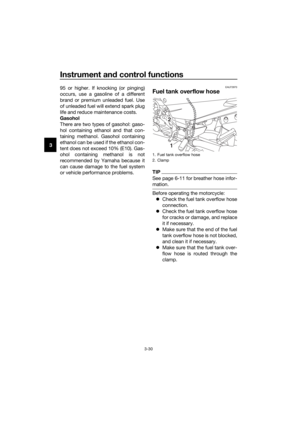 44
44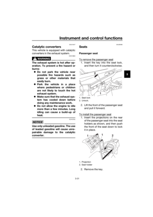 45
45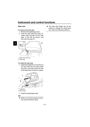 46
46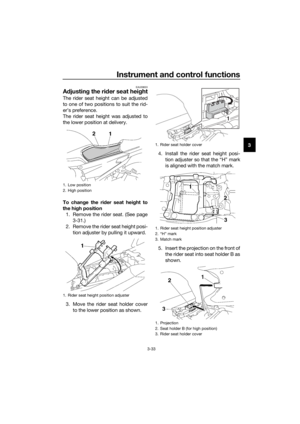 47
47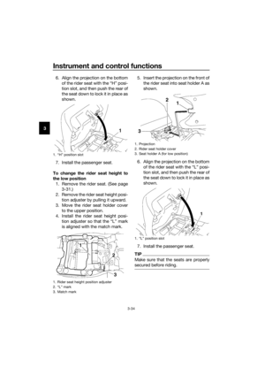 48
48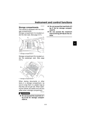 49
49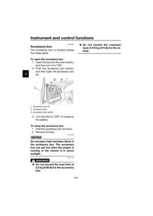 50
50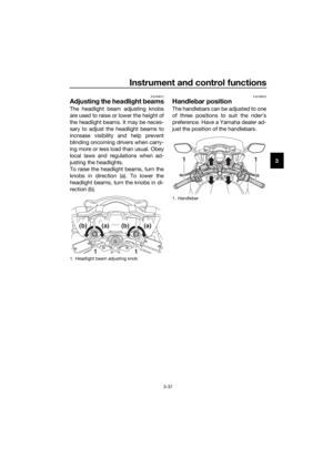 51
51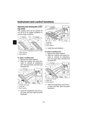 52
52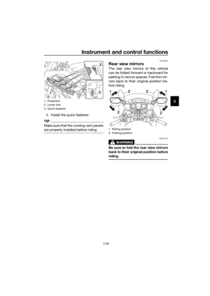 53
53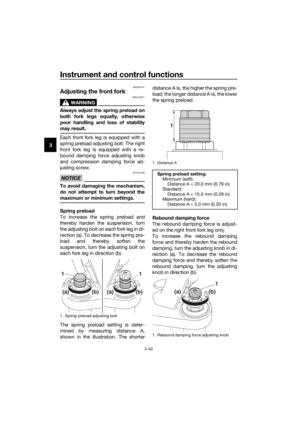 54
54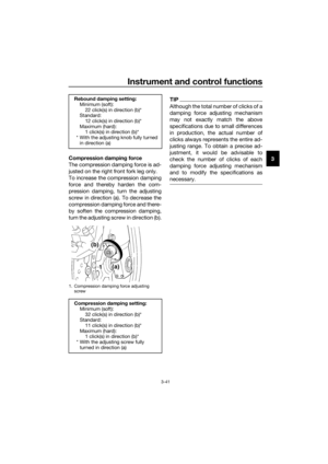 55
55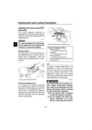 56
56 57
57 58
58 59
59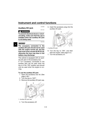 60
60 61
61 62
62 63
63 64
64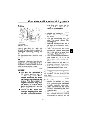 65
65 66
66 67
67 68
68 69
69 70
70 71
71 72
72 73
73 74
74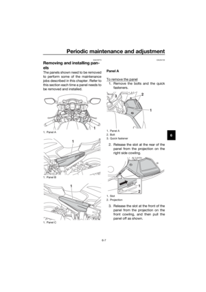 75
75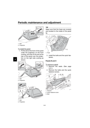 76
76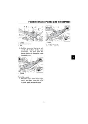 77
77 78
78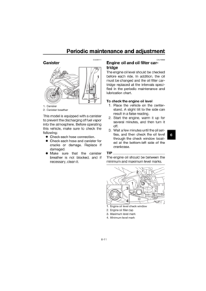 79
79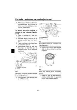 80
80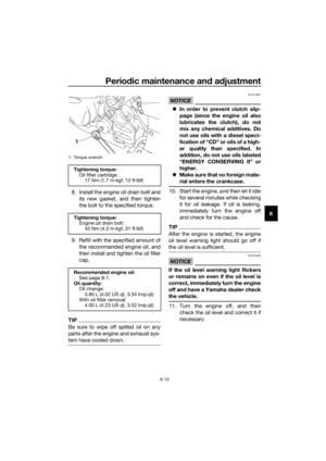 81
81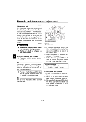 82
82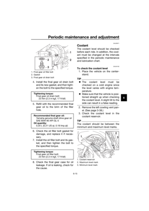 83
83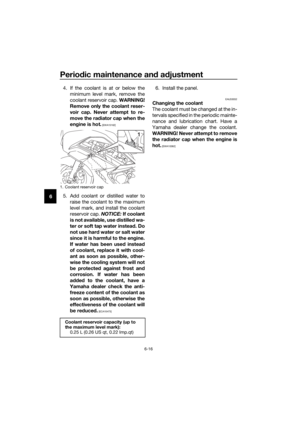 84
84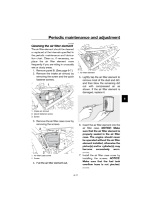 85
85 86
86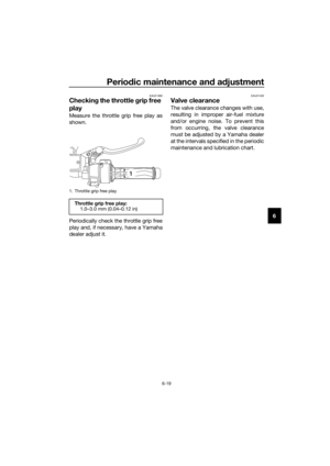 87
87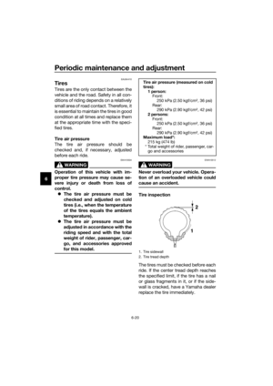 88
88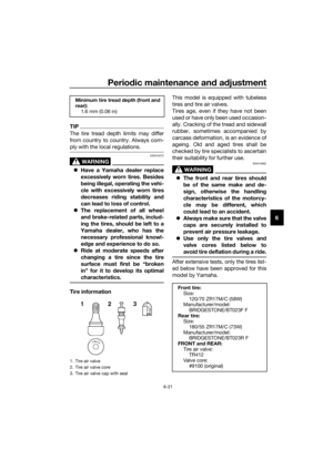 89
89 90
90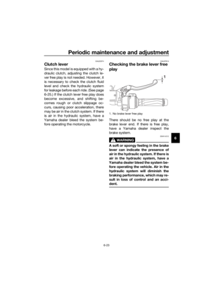 91
91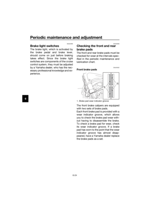 92
92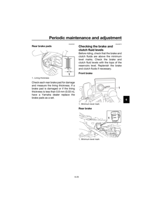 93
93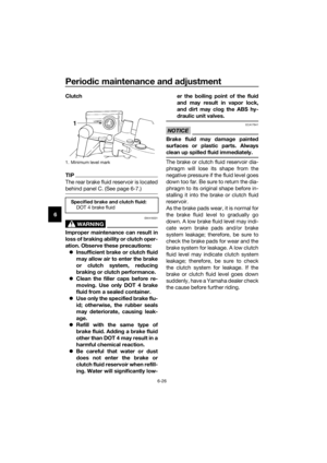 94
94 95
95 96
96 97
97 98
98 99
99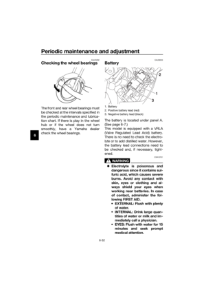 100
100 101
101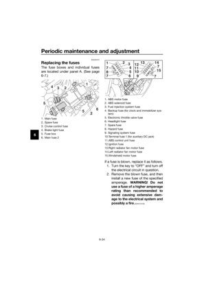 102
102 103
103 104
104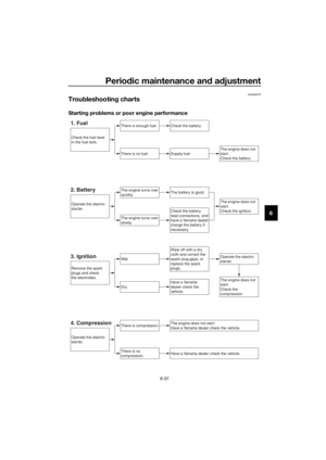 105
105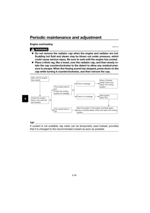 106
106 107
107 108
108 109
109 110
110 111
111 112
112 113
113 114
114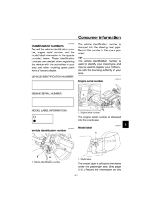 115
115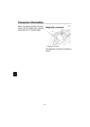 116
116 117
117 118
118 119
119


