2016 VOLVO XC70 service
[x] Cancel search: servicePage 100 of 396

03 Instruments and controls
03
98* Option/accessory, for more information, see Introduction.
Windshield wipers
Move the lever toward the steering wheel to start the windshield and headlight washers.After the lever is released the wipers makeseveral extra sweeps.
Windshield wipers and washers
Rain sensor* on/off
Thumb wheel sensitivity/frequency
CAUTION
• Use ample washer fluid when washing the windshield. The windshield shouldbe thoroughly wet when the wipers arein operation.
• Before using the wipers, ice and snowshould be removed from the wind-shield/rear window. Be sure the wiperblades are not frozen in place.
Windshield wipers offMove the lever to position
0 to
switch off the windshield wipers.
Single sweepMove the lever upward from posi- tion 0 to sweep the windshield one
stroke at a time for as long as the
lever is held up.
Intermittent wipingWith the lever in this position, you can set the wiper interval by twistingthe thumb wheel upward to increase
wiper speed or downward to decrease thespeed.
Continuous wipingThe wipers operate at normal speed.
The wipers operate at high speed.
Windshield wiper service positionThe windshield wipers must be in the service position before the wiper blades can becleaned or replaced. See Wiper blades –service position (p. 342) for additional infor-mation.
Related information
• Engine compartment – washer fluid (p. 344)
Rain sensor*
The rain sensor automatically regulates wiper speed according to the amount of water onthe windshield. The sensitivity of the rain sensor can be adjusted moving the thumb wheel up (thewipers will sweep the windshield more fre-quently) or down (the wipers will sweep thewindshield less frequently).
NOTE
The wipers will make an extra sweep each time the thumb wheel is adjusted upward.
When the rain sensor is activated, the symbol
will illuminate in the instrument panel.
Activating and setting the sensitivityWhen activating the rain sensor, the vehicle must be running or in ignition mode
II and the
windshield wiper lever must be in position 0
or in the single sweep position. Activate the rain sensor by pressing the but- ton
. The windshield wipers will make
one sweep. Press the lever up for the wipers to make an extra sweep. The rain sensor returns to activemode when the stalk is released back toposition 0.
Page 115 of 396

03 Instruments and controls
03
}}
* Option/accessory, for more information, see Introduction.113
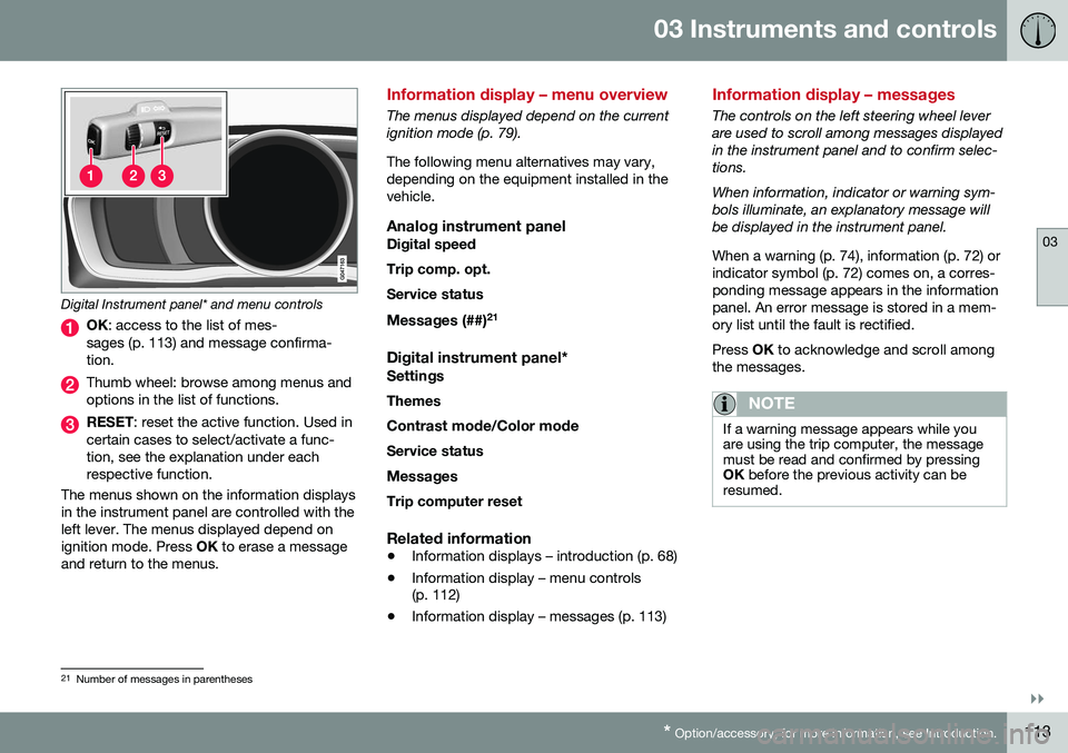
Digital Instrument panel* and menu controls
OK : access to the list of mes-
sages (p. 113) and message confirma- tion.
Thumb wheel: browse among menus and options in the list of functions.
RESET : reset the active function. Used in
certain cases to select/activate a func- tion, see the explanation under eachrespective function.
The menus shown on the information displaysin the instrument panel are controlled with theleft lever. The menus displayed depend onignition mode. Press OK to erase a message
and return to the menus.
Information display – menu overview
The menus displayed depend on the current ignition mode (p. 79). The following menu alternatives may vary, depending on the equipment installed in thevehicle.
Analog instrument panelDigital speed Trip comp. opt.Service status
Messages (##) 21
Digital instrument panel*
Settings
Themes
Contrast mode /Color mode
Service status
Messages Trip computer reset
Related information
• Information displays – introduction (p. 68)
• Information display – menu controls (p. 112)
• Information display – messages (p. 113)
Information display – messages
The controls on the left steering wheel lever are used to scroll among messages displayedin the instrument panel and to confirm selec-tions. When information, indicator or warning sym- bols illuminate, an explanatory message willbe displayed in the instrument panel. When a warning (p. 74), information (p. 72) or indicator symbol (p. 72) comes on, a corres-ponding message appears in the informationpanel. An error message is stored in a mem-ory list until the fault is rectified. Press
OK to acknowledge and scroll among
the messages.
NOTE
If a warning message appears while you are using the trip computer, the messagemust be read and confirmed by pressingOK before the previous activity can be
resumed.
21 Number of messages in parentheses
Page 116 of 396

||
03 Instruments and controls
03
114
MessageDescription
Stop engineAStop and switch off the engine as soon as possi-ble. Serious risk of dam-age. Contact an author-ized Volvo workshop.
Stop safelyAStop and switch off the engine. Serious risk ofdamage. Contact anauthorized Volvo work-shop.
Service urgentAHave the vehicle checked by an authorized Volvoworkshop immediately.
Service requiredAHave the vehicle checked by an authorized Volvoworkshop as soon as pos-sible.
See man- ualARead the owner's manual.
Book time for mainte-nanceTime to book service at an authorized Volvo retailer.
MessageDescription
Time for regularmainte-nanceTime for regular service at an authorized Volvo work-shop. The timing is deter-mined by the number ofmiles driven, number ofmonths since the lastservice, engine runningtime.
Mainte- nance over-dueIf the service intervals are not followed, the warrantydoes not cover any dam-aged parts. Contact anauthorized Volvo work-shop for service.
Temporarily OFFAA function has been tem- porarily switched off andis reset automatically whiledriving or after startingagain.
Low battery Power savemodeThe audio system is switched off to save cur-rent. Charge the battery.
AThere will also be a system-specific part of this message
Related information
• Information displays – introduction (p. 68)
• Information display – menu overview (p. 113) •
Information display – menu controls(p. 112)
Page 119 of 396

03 Instruments and controls
03
}}
117
FunctionDescription
Digital speed – km/h – mph– NoneThis displays the vehicle's speed digitally in the center of the instrument panel
• Open by pressing
OK, scroll using the thumb wheel, confirm by pressing OK and exit by pressing
ENTER .
Trip comp. opt.
–
Distance to empty
– Fuel consumption
– Average speed
– Trip odometer T1 and total dist.
– Trip odometer T2 and total dist.
Selections among the trip computer information headings are made here. The symbols that have already been selected have a check mark and are displayed in white. Those not selected are not checked and
are displayed in gray:
1. Open the function by pressing OK and scroll to the desired heading using the thumb wheel.
2. Confirm by pressing OK. The symbol will change colors from gray to white and will be checked.
3. Continue this procedure or exit by pressing RESET.
Service statusShows the number of months and mileage until the next scheduled service.
Messages (##)For additional information, see Information display – menu controls (p. 112).
Information headingsAny of the information headings in the follow- ing table can be displayed. To do so:
1. Ensure that none of the trip computer
controls are being used in a command sequence; reset them by pressing RESET
twice. 2. Turn the
thumb wheel to begin display-
ing the information headings. Stop on thedesired heading.
3. See the table for an explanation of the heading or the actions that can be taken.
Page 122 of 396

||
03 Instruments and controls
03
120
FunctionDescription
Contrast mode/Color modeAdjust the instrument panel's contrast and color.
Service statusShows the number of months and mileage until the next scheduled service.
Information headingsThree trip computer headings can be dis- played at the same time; one in each of thedisplays (see the previous illustration). One ofthe combinations of information headings inthe following table can be displayed. To doso: 1. Ensure that none of the trip computer
controls are being used in a commandsequence; reset them by pressing RESET
twice.
2. Turn the thumb wheel to begin display-
ing the combinations of information head-ings. Stop on the desired combination. 3. See the table for an explanation of the
heading or the actions that can be taken.
Scroll among the combinations of trip com-puter information headings at any time byturning the thumb wheel until the desired
combination is displayed.
Heading combinationsDescription
Average fuel consump- tionTrip odometer T1 + mile- ageAverage speed•Press and hold
RESET to reset trip odometer T1.
Current fuel consumptionTrip odometer T2 + mile-
ageDistance to empty•Press and hold
RESET to reset trip odometer T2.
Current fuel consumptionMileagemph<>km/hChange between mph<>km/h – see "Digital speed display" in Trip computer – Supplementary information (p. 121).
-No trip computer informa-
tion displayed-No information will be displayed. This also indicates the begin- ning/end of the list of information headings.
Scroll among the trip computer information headings at any time by turning the thumb
wheel until the desired heading is displayed.Related information
•Trip computer – introduction (p. 115)
• Trip computer – functions, analog instru- ment panel (p. 116) •
Trip computer – Supplementary informa-tion (p. 121)
• Trip computer – Trip statistics (p. 122)
Page 126 of 396

04 Climate
04
124* Option/accessory, for more information, see Introduction.
Climate – general information
The vehicle is equipped with Electronic Cli- mate Control (ECC) (p. 128) that cools, heatsor dehumidifies the air in the passenger com-partment.
Air conditioning
NOTE
• The air conditioning can be switched off, but to ensure the best possible cli-mate comfort in the passenger com-partment and to prevent the windowsfrom misting, it should always be on.
• In warm weather, a small amount ofwater may accumulate under the carwhen it has been parked. This water iscondensation from the A/C systemand is normal.
Side windows and moonroofTo ensure that the air conditioning works optimally, the side windows, and the optionalmoonroof should be closed.
Fog on the inside of the windowsThe defroster function (p. 132) should beused to remove fog or mist from the inside ofthe windows. Keeping the windows cleanwith a commercially available window wash-ing spray will also help prevent fogging ormisting.
Temporary shut-off of the air conditioning
The air conditioning (p. 131) is momentarily disengaged during full acceleration or whendriving uphill with a trailer. This may result ina temporary increase in cabin temperature.
Ice and snowAlways keep the air intake grille at the base ofthe windshield free of snow.
Climate system maintenanceSpecial tools and equipment are required tomaintain and carry out repairs on the climatesystem. Work of this type should only bedone by a trained and qualified Volvo servicetechnician.
RefrigerantVolvo cares about the environment. The airconditioning system in your car contains aCFC-free refrigerant – R134a. This substancewill not deplete the ozone layer. The air con-ditioning system contains 1.76 lbs (800 g) ofR134a. The systems uses PAG oil.
Related information
•
Climate – sensors (p. 124)
• Climate – menu settings (p. 126)
Climate – sensors
The climate system utilizes a number of sen- sors to help regulate the temperature andhumidity level in the passenger compartment.
Sensor location
• The sunlight sensor is located on the top side of the dashboard.
NOTE
The sunlight sensor monitors which side of the car that is most exposed to sunlight.This can mean that the temperature maydiffer between the right and left-side airvents, even if the temperatures set for bothsides of the passenger compartment arethe same.
•The temperature sensor for the passen- ger compartment is located below the cli-mate control panel.
• The outside (ambient) temperature sensoris located on the door mirror.
• The humidity sensor* is located in theinterior rearview mirror.
NOTE
Do not cover or block the sensors with clothing or other objects.
Related information
•
Climate – general information (p. 124)
Page 127 of 396

04 Climate
04
}}
* Option/accessory, for more information, see Introduction.125
Air quality
The passenger compartment has been designed to be pleasant and comfortable,even for people with asthma and contactallergies.
Passenger compartment filterReplace the cabin air filter with a new one atthe recommended intervals. Please refer toyour Warranty and Service Records Informa-tion booklet, or consult a trained and qualifiedVolvo service technician for these intervals.The filter should be replaced more often whendriving under dirty and dusty conditions. Thefilter cannot be cleaned and therefore shouldalways be replaced with a new one.
NOTE
There are different types of cabin air filters. Ensure that the correct type is installed.
Interior Air Quality System (IAQS)A multifilter helps reduce gases and particles in the incoming air, thereby reducing the lev-els of odors and contaminants entering thevehicle. The air quality sensor detectsincreased levels of contaminants in the out-side air. When the air quality sensor detectscontaminated outside air, the air intake closesand the air inside the passenger compart-ment is recirculated, i.e., no outside air entersthe vehicle. The filter also cleans recirculatedpassenger compartment air.
NOTE
Contact your Volvo retailer for IAQS air fil- ter replacement intervals.
Materials used in the cabinThe materials used in the cabin have been developed to help minimize the amount ofdust and make the cabin easier to keepclean. All floor mats can be easily removedfor cleaning. Use car cleaning products rec-ommended by Volvo. See also the informa-tion in Cleaning the interior (p. 362).
Related information
• Climate – general information (p. 124)
• Interior Air Quality System (IAQS)* (p. 125)
• Climate – menu settings (p. 126)
Interior Air Quality System (IAQS)*
The Air Quality System (IAQS) consists of a multifilter and an air quality sensor. The filterhelps remove gases and particles from theincoming air, thereby reducing the amounts ofodors and contaminants entering the vehicle. The air quality (p. 125) sensor detects increased levels of contaminants in the out-side air. When the air quality sensor detectscontaminated outside air, the air intake closesand the air inside the passenger compart-ment is recirculated, i.e., no outside air entersthe vehicle. The filter also cleans recirculatedpassenger compartment air. When theAUTO
(p. 131) button is depressed the air
quality sensor is always engaged. Activate or deactivate this function in
Climate
settings
Interior air quality system.
NOTE
• The air quality sensor should always be engaged in order to obtain the bestair in the passenger compartment.
• Recirculation is limited in cold weatherto avoid fogging.
• If the insides of the windows start fog-ging, disengage the air quality sensor.Use the defroster function to increaseairflow to the front, side, and rear win-dows.
Page 156 of 396

||
06 Locks and alarm
06
154
Making a settingDifferent alternatives for locking/unlocking confirmation can be selected in the menus bypressing MY CAR on the center console con-
trol panel. • To activate visual confirmation: go to
SettingsCar settingsLight
settings and select Door lock
confirmation light and/or Unlock
confirmation light by pressing OK/
MENU .
• To activate audible confirmation: go to
SettingsCar settingsLock
settings and select Audible
confirmation by pressing OK/MENU.
For a description of the menu system, see My Car – introduction (p. 76).
Lock indicator
Lock/alarm indicator light A flashing indicator light at the base of the windshield verifies that the vehicle is locked.
Related information
•
Locking/unlocking – from the outside (p. 165)
• Locking/unlocking – from inside (p. 166)
• Locking/unlocking – tailgate (p. 168)
Immobilizer (start inhibitor)
The immobilizer is a start inhibitor that helps prevent unauthorized persons from startingthe engine. Each of the keys supplied with your vehicle contains a coded transponder. The code inthe key is transmitted to an antenna in theignition slot where it is compared to the codestored in the start inhibitor module. The vehi-cle will start only with a properly coded key. Ifyou misplace a key, take the other keys to atrained and qualified Volvo service technicianfor reprogramming as an anti-theft measure.The following messages (which may appear inthe instrument panel display) are related tothe immobilizer: