2016 VOLVO V60 turn signal
[x] Cancel search: turn signalPage 5 of 402

Contents
* Option/accessory, for more information, see Introduction.3
03
03 Instruments and controls
Instrument overview ................................. 63
Information displays – introduction........... 66
Eco Guide* and Power Meter*.................. 69
Information displays – indicator symbols. 70
Information displays – warning symbols... 72
My Car – introduction............................... 74Information displays – ambient tempera-
ture sensor................................................ 75 Information displays – trip odometer and
clock......................................................... 76
Inserting/removing remote key................. 76
Ignition modes.......................................... 77
Front seats................................................ 78
Front seats – folding backrest*................. 79
Front seats – power seat.......................... 79Key memory – power driver's seat* and
door mirrors.............................................. 81
Rear seats – head restraints..................... 82
Rear seats – folding backrest................... 84
Steering wheel.......................................... 85
Electrically heated* steering wheel........... 86
Lighting panel........................................... 87
High/low beam headlights........................ 88
Active high beams (AHB)*......................... 88
03
Tunnel detection (models with the rain
sensor* only)............................................. 90
Active Bending Lights (ABL)*.................... 90
Auxiliary lights*.......................................... 91
Instrument and "theater" lighting.............. 91
Parking lights............................................ 92
Rear fog lights........................................... 92
Hazard warning flashers........................... 93
Turn signals............................................... 93
Front interior lighting................................. 94
Rear interior lighting.................................. 95
Home safe lighting.................................... 95
Approach lighting...................................... 96
Windshield wipers..................................... 96
Rain sensor*.............................................. 97
Windshield washer.................................... 97
Tailgate wiper/washer............................... 98
Power windows......................................... 99
Power door mirrors................................. 100Power door mirrors – automatic tilting/
retraction................................................. 101 Heated windshield*, rear window and
door mirror defrosters............................. 102
Interior rearview mirror............................ 103
03
Digital compass*..................................... 103
Power moonroof* – introduction............. 104
Power moonroof* – operation................. 105 HomeLink ®
Wireless Control System* –
introduction............................................. 106HomeLink ®
Wireless Control System* –
programming........................................... 107
Volvo Sensus.......................................... 110
Information display – menu controls....... 111
Information display – menu overview..... 111
Information display – messages............. 112
Trip computer – introduction ................. 113Trip computer – functions, analog instru-
ment panel.............................................. 114 Trip computer – functions, digital instru-
ment panel.............................................. 117 Trip computer – Supplementary informa-
tion.......................................................... 119
Trip computer – Trip statistics................ 120
Page 7 of 402

Contents
* Option/accessory, for more information, see Introduction.5
06
Locking/unlocking – tailgate................... 162
Alarm – general information.................... 164
Alarm indicator........................................ 165
Alarm – arming/disarming....................... 165
Alarm signal............................................ 166
Alarm – turning off................................... 166
Alarm-related functions........................... 166
07
07 Driver support
Active chassis* (Four C).......................... 169
Stability system – introduction................ 169
Stability system – operation.................... 170Stability system – symbols and mes-
sages....................................................... 172
Adjustable steering force*....................... 174 Road Sign Information (RSI)* – introduc-
tion.......................................................... 174
Road Sign Information (RSI) – operation 175
Road Sign Information (RSI) – limitations 175
Cruise control (CC) – introduction.......... 176Cruise control (CC) – engaging and set-
ting speed............................................... 176 Toggling between ACC and CC (stand-
ard Cruise Control).................................. 178
Cruise control (CC) – deactivating.......... 178
Adaptive Cruise Control – introduction... 179
Adaptive Cruise Control – function......... 180
Adaptive Cruise Control – engaging....... 182
Adaptive Cruise Control – setting speed 183Adaptive Cruise Control – setting time
interval..................................................... 184
Adaptive Cruise Control – deactivating.. 184Adaptive Cruise Control – passing
another vehicle........................................ 186
07
Adaptive Cruise Control (ACC) – Queue
Assist...................................................... 186
Radar sensor........................................... 188
Adaptive Cruise Control – limitations...... 188Adaptive Cruise Control – symbols and
messages................................................ 190 Adaptive Cruise Control – troubleshoot-
ing........................................................... 192
Distance Alert – introduction................... 193
Distance Alert – operation....................... 193
Distance Alert – limitations...................... 194
Distance Alert – symbols and messages 196
City Safety – introduction........................ 197
City Safety – function.............................. 198
City Safety – operation............................ 199
City Safety – limitations.......................... 199
City Safety – troubleshooting.................. 200
City Safety – symbols and messages..... 202
City Safety – Laser sensor...................... 203
Collision warning – introduction.............. 204
Collision warning* – function................... 206
Collision warning* – operation................ 207
Collision warning* – Cyclist detection..... 208Collision warning* – Pedestrian detec-
tion.......................................................... 209
Page 10 of 402

Contents
8* Option/accessory, for more information, see Introduction.
09
09 Wheels and tires
Tires – general information...................... 293
Tires – storage and age.......................... 294
Tires – tread wear indicator.................... 295
Tires – tire economy................................ 295
Changing a wheel – direction of rotation 296
Changing a wheel – removing wheel...... 296
Changing a wheel – spare wheel............ 299Changing a wheel – accessing the spare
wheel....................................................... 300
Changing a wheel – installing a wheel.... 300
Tire inflation – general information.......... 301
Tire inflation – checking pressure........... 302
Tire specifications................................... 303
Tire inflation – pressure table.................. 305
Loading specifications............................ 306
Loading specifications – load limit.......... 306
Tire specifications – terminology............ 307Tire specifications – Uniform Tire Quality
Grading................................................... 308
Snow chains............................................ 309
Snow tires/studded tires......................... 310
Tire pressure monitoring - introduction.. 310Tire Pressure Monitoring System (TPMS)
– general information.............................. 311
09
Tire Pressure Monitoring System (TPMS)
– changing wheels.................................. 312 Tire Pressure Monitoring System (TPMS)
– recalibrating......................................... 313 Tire Pressure Monitoring System (TPMS)
– activating/deactivating......................... 314 Tire Pressure Monitoring System (TPMS)
– messages............................................. 314
Tire Monitor - introduction...................... 315
Calibrating Tire Monitor.......................... 316
Tire Monitor status information............... 316
Tire Monitor – messages......................... 317Tire sealing system* – general informa-
tion.......................................................... 318
Tire sealing system* – overview.............. 320
Tire sealing system* – sealing hole......... 321Tire sealing system – checking inflation
pressure.................................................. 323
Tire sealing system* – inflating tires........ 323Tire sealing system* – sealing compound
container................................................. 324
10
10 Maintenance and servicing
Maintenance – introduction.................... 326
Maintenance – owner maintenance........ 327
Maintenance – hoisting........................... 328
Onboard Diagnostic System................... 329
Booking service and repairs .................. 329
Maintenance – opening/closing hood..... 331
Engine compartment – overview............ 332
Engine compartment – engine oil........... 333
Engine compartment – coolant............... 335
Engine compartment – brake fluid.......... 336Engine compartment – power steering
fluid......................................................... 337
Bulbs – introduction................................ 338
Bulbs – headlight housing....................... 339
Bulbs – cover.......................................... 340
Bulbs – low beam, Halogen.................... 341
Bulbs – high beam, Halogen................... 341
Bulbs – extra high beam......................... 342
Bulbs – front turn signals........................ 343
Bulbs – taillight housing.......................... 343
Bulbs – license plate lighting.................. 344
Bulbs – cargo area lighting..................... 344
Bulbs – vanity mirror lighting.................. 345
Bulbs – specifications............................. 345
Page 67 of 402

03 Instruments and controls
03
* Option/accessory, for more information, see Introduction.65
FunctionSee
Controls for menus and messages, turnsignals, high/lowbeams, trip computer(p. 74), (p. 93),(p. 87),(p. 113)
Paddles for manually shifting gears*(p. 259)
Cruise control(p. 176)
Horn, airbag(p. 85), (p. 33)
Main instrument panel(p. 66)
Infotainment system/ Bluetooth hands-freecontrolsSensus Info- tainmentsupplement
START/STOP ENGINE button(p. 76)
Ignition slot(p. 76)
Display for infotain- ment system func-tions and menus(p. 111), Sensus Info-tainmentsupplement
Door handle-
FunctionSee
In-door control pan- els (power windows,mirrors, central lock-ing button)(p. 99), (p. 100),(p. 160)
Hazard warning flashers(p. 93)
Controls for the info- tainment system andmenus(p. 74), (p. 126),Sensus Info-tainmentsupplement
Climate system con- trols(p. 126)
Gear selector(p. 257)
Controls for active chassis (Four-C)*(p. 169)
Wipers and washers(p. 96), (p. 97)
Steering wheel adjustment(p. 85)
Hood opening control(p. 331)
Parking brake(p. 274)
FunctionSee
Power seat* adjust- ment controls(p. 79)
Lighting panel, but- tons for opening fuelfiller door andunlocking the tailgate(p. 87), (p. 283),(p. 162)
Related information
• Information displays – ambient tempera- ture sensor (p. 75)
• Information displays – trip odometer andclock (p. 76)
Page 72 of 402

||
03 Instruments and controls
03
70* Option/accessory, for more information, see Introduction.
Available powerThe smaller, upper indicator shows the engine's available power 2
. The higher the
reading on the scale, the greater the amount of power remaining in the current gear.
Utilized powerThe larger, lower indicator shows the amount of engine power that has been utilized 2
. The
higher the reading on the scale, the greater the amount of power that is being utilized. The larger the gap between the two indica- tors, the greater the amount of power remain-ing.
Information displays – indicator symbols
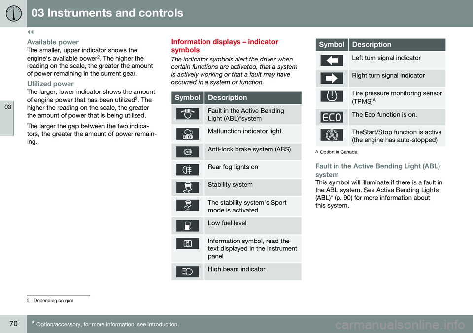
The indicator symbols alert the driver when certain functions are activated, that a systemis actively working or that a fault may haveoccurred in a system or function.
SymbolDescription
Fault in the Active Bending Light (ABL)*system
Malfunction indicator light
Anti-lock brake system (ABS)
Rear fog lights on
Stability system
The stability system's Sport mode is activated
Low fuel level
Information symbol, read the text displayed in the instrumentpanel
High beam indicator
SymbolDescription
Left turn signal indicator
Right turn signal indicator
Tire pressure monitoring sensor (TPMS) A
The Eco function is on.
TheStart/Stop function is active (the engine has auto-stopped)
A
Option in Canada
Fault in the Active Bending Light (ABL)
system
This symbol will illuminate if there is a fault in the ABL system. See Active Bending Lights(ABL)* (p. 90) for more information aboutthis system.
2 Depending on rpm
Page 73 of 402

03 Instruments and controls
03
}}
* Option/accessory, for more information, see Introduction.71
Malfunction Indicator LightAs you drive, a computer called On-Board Diagnostics II (OBDII) monitors your vehicle'sengine, transmission, electrical and emissionsystems. The malfunction indicator light will illuminate if the computer senses a condition that poten-tially may need correcting. When this hap-pens, please have your vehicle checked by atrained and qualified Volvo service technicianas soon as possible. A malfunction indicator light may have many causes. Sometimes, you may not notice achange in your car's behavior. Even so, anuncorrected condition could hurt fuel econ-omy, emission controls, and drivability.Extended driving without correcting the causecould even damage other components inyour vehicle. This light may illuminate if the fuel filler cap is not closed tightly or if the engine was runningwhile the vehicle was refueled.
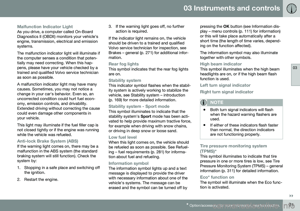
Anti-lock Brake System (ABS)If the warning light comes on, there may be a malfunction in the ABS system (the standardbraking system will still function). Check thesystem by:
1. Stopping in a safe place and switching off
the ignition.
2. Restart the engine. 3. If the warning light goes off, no further
action is required.
If the indicator light remains on, the vehicle should be driven to a trained and qualifiedVolvo service technician for inspection, seeBrakes – general (p. 271) for additional infor-mation.
Rear fog lightsThis symbol indicates that the rear fog lights are on.
Stability systemThis indicator symbol flashes when the stabil- ity system is actively working to stabilize thevehicle, see Stability system – introduction(p. 169) for more detailed information.
Stability system - Sport modeThis symbol illuminates to indicate that the stability system's Sport mode has been acti-
vated to help provide maximum tractive force,for example when driving with snow chains,or driving in deep snow or loose sand.
Low fuel levelWhen this light comes on, the vehicle should be refueled as soon as possible. See Refuel-ing – fuel requirements (p. 281) for informa-tion about fuel and refueling.
Information symbolThe information symbol lights up and a text message is displayed to provide the driverwith necessary information about one of thevehicle's systems. The message can beerased and the symbol can be turned off by pressing the
OK button (see Information dis-
play – menu controls (p. 111) for information)or this will take place automatically after ashort time (the length of time varies, depend-ing on the function affected). The information symbol may also illuminate together with other symbols.
High beam indicatorThis symbol illuminates when the high beam headlights are on, or if the high beam flashfunction is used.
Left turn signal indicator
Right turn signal indicator
NOTE
• Both turn signal indicators will flash when the hazard warning flashers areused.
• If either of these indicators flash fasterthan normal, the direction indicatorsare not functioning properly.
Tire pressure monitoring system (TPMS)*
This symbol illuminates to indicate that tire pressure in one or more tires is low, see TirePressure Monitoring System (TPMS) – generalinformation (p. 311) for detailed information.
Eco* function onThe symbol will illuminate when the Eco func- tion is activated.
Page 75 of 402

03 Instruments and controls
03
}}
73
Generator not chargingThis symbol comes on during driving if a fault has occurred in the electrical system. Contactan authorized Volvo workshop.
Engine temperatureEngine overheating can result from low oil or coolant levels, towing or hard driving at highheat and altitude, or mechanical malfunction.Engine overheating will be signaled with textand a red warning triangle in the middle of theinstrument display. The exact text will dependon the degree of overheating. It may range from
High engine temp Reduce speed toHigh engine temp Stop engine. If appropri-
ate, other messages, such as Coolant level
low, Stop safely will also be displayed. If
your engine does overheat so that you must stop the engine, always allow the engine tocool before attempting to check oil and cool-ant levels. See Engine compartment – coolant (p. 335) for more information.
Fault in brake systemIf this symbol lights, the brake fluid level may be too low. Stop the vehicle in a safe placeand check the level in the brake fluid reser-voir, see Engine compartment – brake fluid(p. 336). If the level in the reservoir is belowMIN , the vehicle should be transported to an
authorized Volvo workshop to have the brakesystem checked. If the
and symbols come on
at the same time, there may be a fault in the brake force distribution system.
1. Stop the vehicle in a safe place and turn off the engine.
2. Restart the engine.
• If both symbols extinguish, continue driv- ing.
• If the symbols remain on, check the levelin the brake fluid reservoir, see Enginecompartment – brake fluid (p. 336). If thebrake fluid level is normal but the sym-bols are still lit, the vehicle can be driven,with great care, to an authorized Volvoworkshop to have the brake systemchecked.
• If the level in the reservoir is below
MIN,
the vehicle should be transported to anauthorized Volvo workshop to have thebrake system checked.WARNING
• If the fluid level is below the
MIN mark
in the reservoir or if a warning mes- sage is displayed in the text window:DO NOT DRIVE . Have the vehicle
towed to a trained and qualified Volvoservice technician and have the brakesystem inspected.
• If the
and symbols
are on at the same time, there is a risk of reduced vehicle stability.
Warning symbolThe red warning symbol lights up to indicate a problem related to safety and/or drivability.A message will also appear in the instrumentpanel. The symbol remains visible until thefault has been rectified but the text messagecan be cleared with the OK button, see Infor-
mation display – menu controls (p. 111). Thewarning symbol can also come on in conjunc-tion with other symbols. Action:
1. Stop in a safe place. Do not drive the vehicle further.
2. Read the information on the display. Implement the action in accordance with the message in the display. Clear themessage using OK.
Page 93 of 402

03 Instruments and controls
03
* Option/accessory, for more information, see Introduction.91
Cornering lights 18Models equipped with ABL also have front cornering lights that temporarily provide extralight to the front left or right of the vehicle atlow speeds when making a sharp turn (forexample, when turning into a parking space)or when the turn signals are used. This feature is activated when: •
High or low beam headlights are on
and
• The vehicle's speed is below 20 mph (30 km/h)
The feature is also activated when the vehicle is backing up. The cornering lights are deactivated when the vehicle's speed exceeds approx. 25 mph(40 km/h).
Related information
• Lighting panel (p. 87)
• High/low beam headlights (p. 88)
• Active high beams (AHB)* (p. 88)
Auxiliary lights*
If the vehicle is fitted with auxiliary lights, the driver can use the
MY CAR menu system to
choose to deactivate and turn these lights onand off along with the high beam headlights. The auxiliary lights must be connected to the vehicle's electrical system, which should onlybe done by a trained and authorized Volvoservice technician. See My Car – introduction(p. 74) for more information about the menusystem.
Instrument and "theater" lighting
Instrument lightingIllumination of the display and instrument lights will vary, depending on ignition mode. The display lighting is automatically subdued in darkness and the sensitivity is set with thethumb wheel. The intensity of the instrument lighting is adjusted with the thumb wheel.
"Theater" lightingWhen the overhead courtesy lighting hasgone out and the engine is running, severalLEDs located near the roof console illuminateto provide faint lighting for the occupants ofthe front seats. This lighting goes out justafter the overhead courtesy lighting when thevehicle is locked.
Related information
• Lighting panel (p. 87)
• Front interior lighting (p. 94)
• Rear interior lighting (p. 95)
• Ignition modes (p. 77)
18
Certain models only