2016 VOLVO V60 CROSS COUNTRY instrument panel
[x] Cancel search: instrument panelPage 225 of 402
07 Driver support
07
}}
223
Lane Departure Warning (LDW) – operation
Operation and function
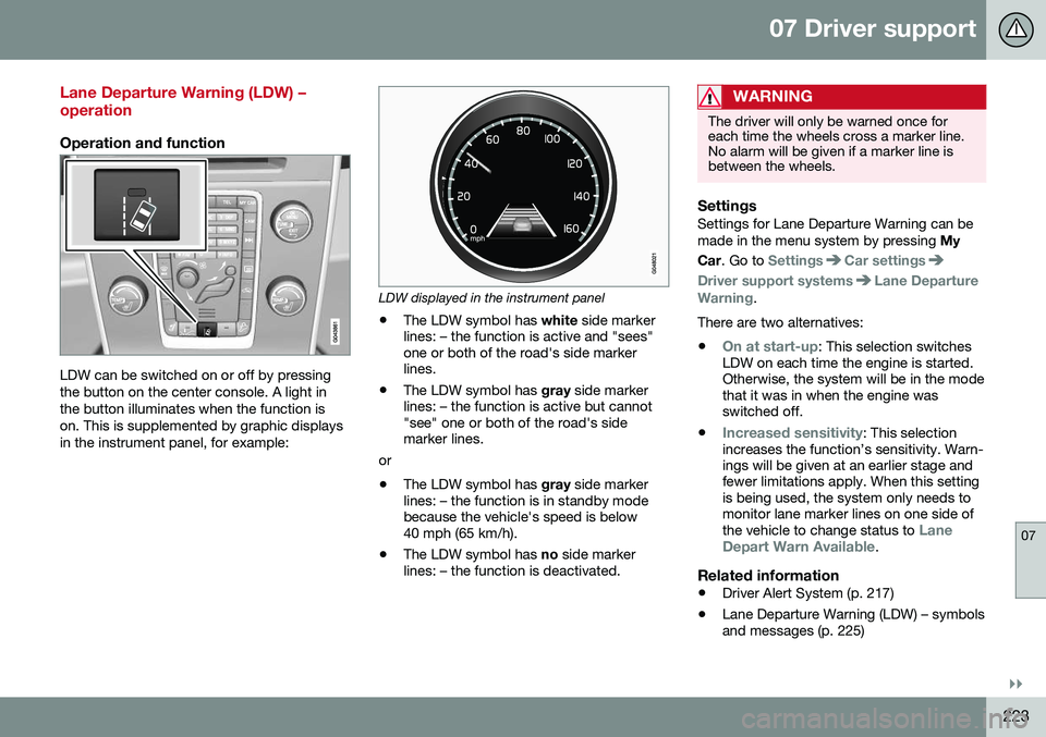
LDW can be switched on or off by pressing the button on the center console. A light inthe button illuminates when the function ison. This is supplemented by graphic displaysin the instrument panel, for example:
LDW displayed in the instrument panel
• The LDW symbol has
white side marker
lines: – the function is active and "sees" one or both of the road's side markerlines.
• The LDW symbol has
gray side marker
lines: – the function is active but cannot"see" one or both of the road's sidemarker lines.
or
• The LDW symbol has
gray side marker
lines: – the function is in standby modebecause the vehicle's speed is below40 mph (65 km/h).
• The LDW symbol has
no side marker
lines: – the function is deactivated.
WARNING
The driver will only be warned once for each time the wheels cross a marker line.No alarm will be given if a marker line isbetween the wheels.
SettingsSettings for Lane Departure Warning can be made in the menu system by pressing My
Car . Go to
SettingsCar settings
Driver support systemsLane Departure
Warning.
There are two alternatives:
•
On at start-up: This selection switches
LDW on each time the engine is started. Otherwise, the system will be in the modethat it was in when the engine wasswitched off.
•
Increased sensitivity: This selection
increases the function’s sensitivity. Warn- ings will be given at an earlier stage andfewer limitations apply. When this settingis being used, the system only needs tomonitor lane marker lines on one side of the vehicle to change status to
Lane
Depart Warn Available.
Related information
• Driver Alert System (p. 217)
• Lane Departure Warning (LDW) – symbols and messages (p. 225)
Page 233 of 402

07 Driver support
07
231
Lane Keeping Aid (LKA) – symbols and messages
A text message can be erased by pressing briefly on the OK button on the turn signal
lever.
SymbolMessageDescription
-Lane Keeping Aid Unavailable
at this speedThe function has gone into standby mode because the vehicle's speed is below 40 mph (65 km/h).
-Lane Keeping Aid Unavailable
for current markingsThe road lacks clear marker lines or the camera is not functioning properly. See The camera’s limitations (p. 212) for information on the camera’s limitations.
-Lane Keeping Aid AvailableThe function is monitoring the road’s marker lines.
Windscreen sensors blocked See manualThe camera is temporarily not functioning, due to snow, ice, or dirt on the windshield. Clean the area of the windshield in front of the camera. See The camera’s limitations (p. 212) for informa-tion on the camera’s limitations.
Lane Keeping Aid Service requiredThe system is not functioning. Contact a trained and qualified Volvo service technician if the message remains in the display.
Lane Keeping Aid InterruptedThe function has gone into standby mode. The lines in the LKA symbol in the instrument panel will indicate when the function is active again.
Related information
• Driver Alert System (p. 217)
• Lane Keeping Aid (LKA) – introduction (p. 227)
• Lane Keeping Aid (LKA) – operation(p. 228) •
Lane Keeping Aid (LKA) – limitations(p. 230)
Page 238 of 402
07 Driver support
07
236* Option/accessory, for more information, see Introduction.
Park Assist Pilot (PAP)* – introduction
The Park Assist Pilot provides assistance when parallel parking by measuring the park-ing space and turning the steering wheel.
Introduction
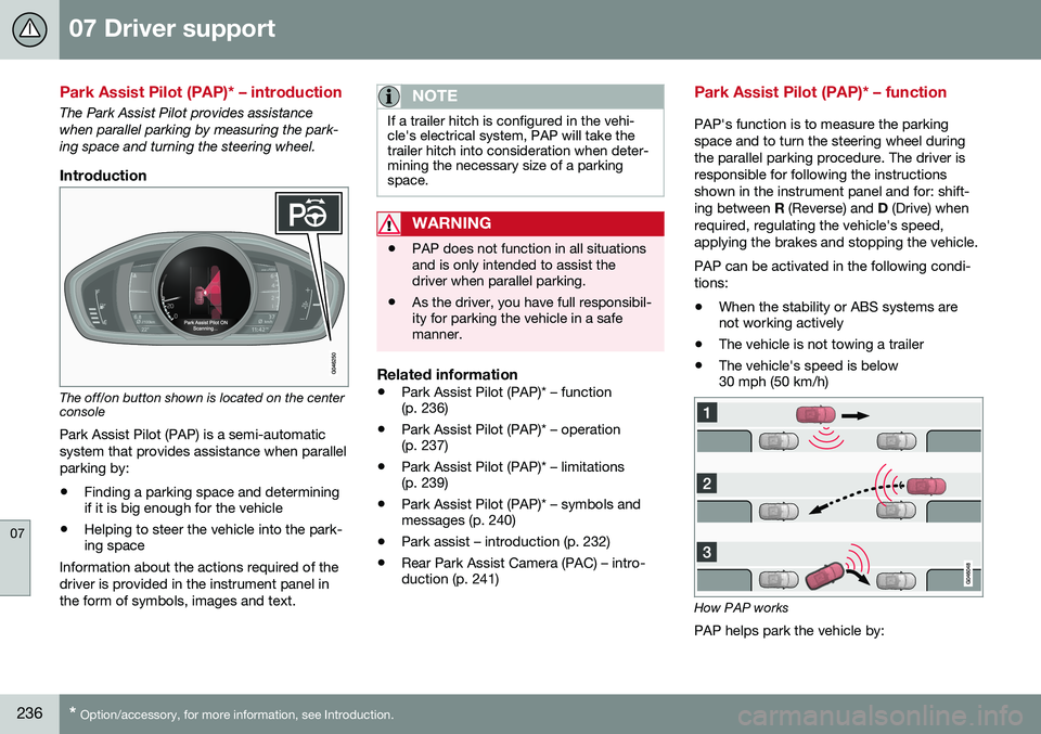
The off/on button shown is located on the center console
Park Assist Pilot (PAP) is a semi-automatic system that provides assistance when parallelparking by:
• Finding a parking space and determining if it is big enough for the vehicle
• Helping to steer the vehicle into the park-ing space
Information about the actions required of the driver is provided in the instrument panel inthe form of symbols, images and text.
NOTE
If a trailer hitch is configured in the vehi- cle's electrical system, PAP will take thetrailer hitch into consideration when deter-mining the necessary size of a parkingspace.
WARNING
• PAP does not function in all situations and is only intended to assist thedriver when parallel parking.
• As the driver, you have full responsibil-ity for parking the vehicle in a safemanner.
Related information
•
Park Assist Pilot (PAP)* – function (p. 236)
• Park Assist Pilot (PAP)* – operation(p. 237)
• Park Assist Pilot (PAP)* – limitations(p. 239)
• Park Assist Pilot (PAP)* – symbols andmessages (p. 240)
• Park assist – introduction (p. 232)
• Rear Park Assist Camera (PAC) – intro-duction (p. 241)
Park Assist Pilot (PAP)* – function
PAP's function is to measure the parking space and to turn the steering wheel duringthe parallel parking procedure. The driver isresponsible for following the instructionsshown in the instrument panel and for: shift-ing between
R (Reverse) and D (Drive) when
required, regulating the vehicle's speed,applying the brakes and stopping the vehicle. PAP can be activated in the following condi- tions: • When the stability or ABS systems are not working actively
• The vehicle is not towing a trailer
• The vehicle's speed is below30 mph (50 km/h)
How PAP works
PAP helps park the vehicle by:
Page 240 of 402
||
07 Driver support
07
238* Option/accessory, for more information, see Introduction.
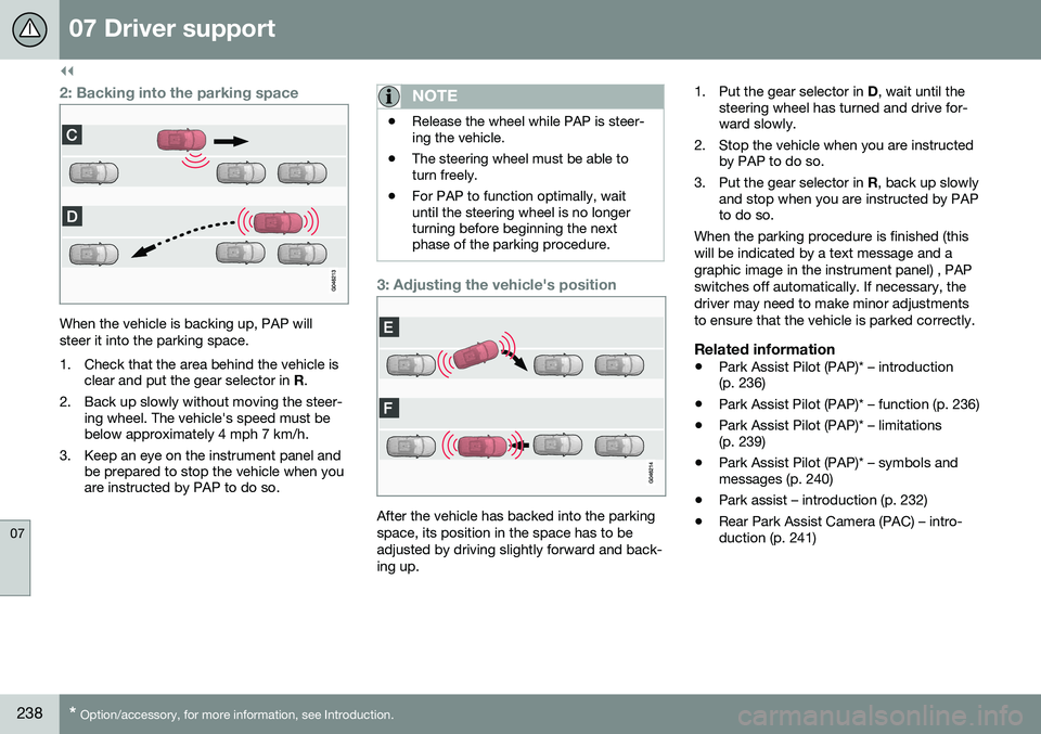
2: Backing into the parking space
When the vehicle is backing up, PAP will steer it into the parking space.
1. Check that the area behind the vehicle is
clear and put the gear selector in R.
2. Back up slowly without moving the steer- ing wheel. The vehicle's speed must be below approximately 4 mph 7 km/h.
3. Keep an eye on the instrument panel and be prepared to stop the vehicle when youare instructed by PAP to do so.
NOTE
•Release the wheel while PAP is steer- ing the vehicle.
• The steering wheel must be able toturn freely.
• For PAP to function optimally, waituntil the steering wheel is no longerturning before beginning the nextphase of the parking procedure.
3: Adjusting the vehicle's position
After the vehicle has backed into the parking space, its position in the space has to beadjusted by driving slightly forward and back-ing up. 1. Put the gear selector in
D, wait until the
steering wheel has turned and drive for- ward slowly.
2. Stop the vehicle when you are instructed by PAP to do so.
3. Put the gear selector in R, back up slowly
and stop when you are instructed by PAPto do so.
When the parking procedure is finished (this will be indicated by a text message and agraphic image in the instrument panel) , PAPswitches off automatically. If necessary, thedriver may need to make minor adjustmentsto ensure that the vehicle is parked correctly.
Related information
• Park Assist Pilot (PAP)* – introduction (p. 236)
• Park Assist Pilot (PAP)* – function (p. 236)
• Park Assist Pilot (PAP)* – limitations(p. 239)
• Park Assist Pilot (PAP)* – symbols andmessages (p. 240)
• Park assist – introduction (p. 232)
• Rear Park Assist Camera (PAC) – intro-duction (p. 241)
Page 242 of 402

||
07 Driver support
07
240* Option/accessory, for more information, see Introduction.
The sensors must be cleaned regularly to ensure that they work properly. Clean themwith water and a suitable car washing deter-gent.
Related information
• Park Assist Pilot (PAP)* – introduction (p. 236)
• Park Assist Pilot (PAP)* – function (p. 236)
• Park Assist Pilot (PAP)* – operation(p. 237)
• Park Assist Pilot (PAP)* – symbols andmessages (p. 240)
• Park assist – introduction (p. 232)
• Rear Park Assist Camera (PAC) – intro-duction (p. 241)
Park Assist Pilot (PAP)* – symbols and messages
Various PAP-related combinations of sym- bols, graphics and text messages are dis-played in the instrument panel and some-times also include suitable actions. A text message can be erased by pressing briefly on the
OK button on the turn signal
lever. Contact a Volvo retailer or a trained and qualified Volvo service technician If a mes-sage indicating that PAP is not functioningproperly is displayed.
Related information
• Park Assist Pilot (PAP)* – introduction (p. 236)
• Park Assist Pilot (PAP)* – function (p. 236)
• Park Assist Pilot (PAP)* – operation(p. 237)
• Park Assist Pilot (PAP)* – limitations(p. 239)
• Park assist – introduction (p. 232)
• Rear Park Assist Camera (PAC) – intro-duction (p. 241)
Park assist – troubleshooting
Faults in the systemIf the information symbol illuminates andPark assist syst Service required is shown
on the information display, this indicates that the system is not functioning properly andhas been disengaged. Consult a trained andqualified Volvo service technician.
CAUTION
In certain circumstances, the park assist system may give unexpected warning sig-nals that can be caused by external soundsources that use the same ultrasound fre-quencies as the system. This may includesuch things as the horns of other vehicles,wet tires on asphalt, pneumatic brakes,motorcycle exhaust pipes, etc. This doesnot indicate a fault in the system.
Related information
• Park assist – introduction (p. 232)
• Park assist – limitations (p. 235)
• Park assist – function (p. 232)
• Park assist – operation (p. 234)
• Rear Park Assist Camera (PAC) – function (p. 241)
Page 249 of 402
07 Driver support
07
}}
* Option/accessory, for more information, see Introduction.247
BLIS* – operation
Activating/deactivating BLIS
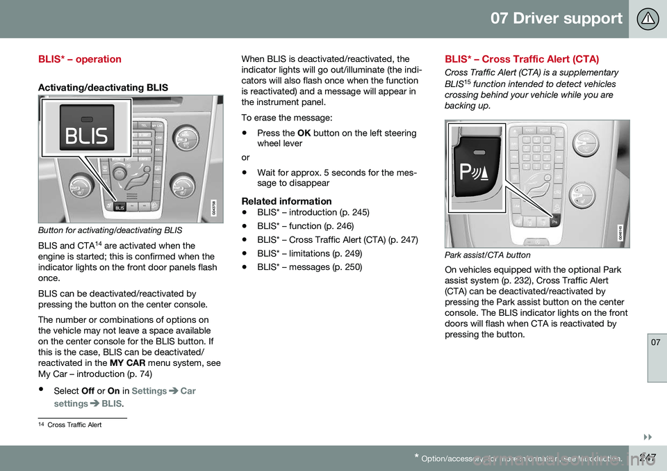
Button for activating/deactivating BLIS BLIS and CTA 14
are activated when the
engine is started; this is confirmed when the indicator lights on the front door panels flashonce. BLIS can be deactivated/reactivated by pressing the button on the center console. The number or combinations of options on the vehicle may not leave a space availableon the center console for the BLIS button. Ifthis is the case, BLIS can be deactivated/reactivated in the MY CAR menu system, see
My Car – introduction (p. 74)
• Select Off or On in
SettingsCar
settings
BLIS. When BLIS is deactivated/reactivated, the indicator lights will go out/illuminate (the indi-cators will also flash once when the functionis reactivated) and a message will appear inthe instrument panel. To erase the message: •
Press the
OK button on the left steering
wheel lever
or
• Wait for approx. 5 seconds for the mes- sage to disappear
Related information
•BLIS* – introduction (p. 245)
• BLIS* – function (p. 246)
• BLIS* – Cross Traffic Alert (CTA) (p. 247)
• BLIS* – limitations (p. 249)
• BLIS* – messages (p. 250)
BLIS* – Cross Traffic Alert (CTA)
Cross Traffic Alert (CTA) is a supplementary BLIS 15
function intended to detect vehicles
crossing behind your vehicle while you are backing up.
Park assist/CTA button On vehicles equipped with the optional Park assist system (p. 232), Cross Traffic Alert(CTA) can be deactivated/reactivated bypressing the Park assist button on the centerconsole. The BLIS indicator lights on the frontdoors will flash when CTA is reactivated bypressing the button.
14 Cross Traffic Alert
Page 252 of 402
07 Driver support
07
250* Option/accessory, for more information, see Introduction.
BLIS* – messages
If BLIS/CTA 18
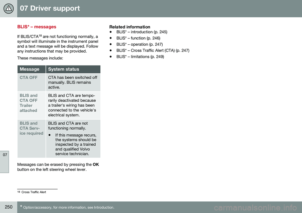
are not functioning normally, a
symbol will illuminate in the instrument panel and a text message will be displayed. Followany instructions that may be provided. These messages include:
MessageSystem status
CTA OFFCTA has been switched off manually. BLIS remainsactive.
BLIS and CTA OFFTrailerattachedBLIS and CTA are tempo- rarily deactivated becausea trailer's wiring has beenconnected to the vehicle'selectrical system.
BLIS and CTA Serv-ice requiredBLIS and CTA are not functioning normally.
• If this message recurs, the systems should beinspected by a trainedand qualified Volvoservice technician.
Messages can be erased by pressing the
OK
button on the left steering wheel lever.
Related information
• BLIS* – introduction (p. 245)
• BLIS* – function (p. 246)
• BLIS* – operation (p. 247)
• BLIS* – Cross Traffic Alert (CTA) (p. 247)
• BLIS* – limitations (p. 249)
18
Cross Traffic Alert
Page 257 of 402
08 Starting and driving
08
* Option/accessory, for more information, see Introduction.255
Engine Remote Start (ERS)* – starting the engine
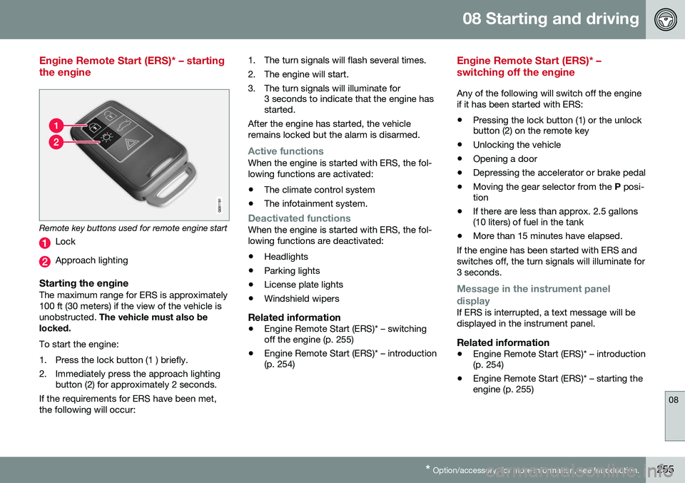
Remote key buttons used for remote engine start
Lock
Approach lighting
Starting the engineThe maximum range for ERS is approximately 100 ft (30 meters) if the view of the vehicle isunobstructed. The vehicle must also be
locked. To start the engine:
1. Press the lock button (1 ) briefly.
2. Immediately press the approach lighting button (2) for approximately 2 seconds.
If the requirements for ERS have been met, the following will occur: 1. The turn signals will flash several times.
2. The engine will start.
3. The turn signals will illuminate for
3 seconds to indicate that the engine has started.
After the engine has started, the vehicle remains locked but the alarm is disarmed.
Active functionsWhen the engine is started with ERS, the fol- lowing functions are activated: • The climate control system
• The infotainment system.
Deactivated functionsWhen the engine is started with ERS, the fol- lowing functions are deactivated: •Headlights
• Parking lights
• License plate lights
• Windshield wipers
Related information
•
Engine Remote Start (ERS)* – switching off the engine (p. 255)
• Engine Remote Start (ERS)* – introduction(p. 254)
Engine Remote Start (ERS)* – switching off the engine
Any of the following will switch off the engine if it has been started with ERS:
• Pressing the lock button (1) or the unlock button (2) on the remote key
• Unlocking the vehicle
• Opening a door
• Depressing the accelerator or brake pedal
• Moving the gear selector from the
P posi-
tion
• If there are less than approx. 2.5 gallons(10 liters) of fuel in the tank
• More than 15 minutes have elapsed.
If the engine has been started with ERS and switches off, the turn signals will illuminate for3 seconds.
Message in the instrument panel
display
If ERS is interrupted, a text message will be displayed in the instrument panel.
Related information
• Engine Remote Start (ERS)* – introduction (p. 254)
• Engine Remote Start (ERS)* – starting theengine (p. 255)