2016 VOLVO V60 CROSS COUNTRY lock
[x] Cancel search: lockPage 112 of 402
03 Instruments and controls
03
110* Option/accessory, for more information, see Introduction.
Volvo Sensus
Volvo Sensus is the core of the contact inter- face with your vehicle. Sensus provides infor-mation, entertainment and offers access tofunctions that make owning and operating aVolvo easier.
Volvo Sensus is the operating system in your vehicle and it enables you to interact intui-tively with the vehicle’s various features andfunctions, including accessing the Internet,when it suits you. Volvo Sensus uses the center console screen to display information and menus, and tooffer a user interface that enables you tomake personalized settings for e.g., vehicle,infotainment and climate system functions. The buttons on the center console or the steering wheel keypad are used to activate/deactivate functions and change numeroussettings. Pressing the MY CAR button on the center
console displays all of the settings related to driving and operating the vehicle, such as City Safety, lock and alarm functions, auto-matic blower speed, setting the clock, etc. Pressing the source buttons on the center console (
RADIO, MEDIA , TEL ,
, NAV * and
CAM *, etc.) make it possible to select e.g.,
AM or FM radio, play a CD or DVD, use the Bluetooth ®
hands-free feature, the navigation
system* or the park assist camera*. See your on-board owner’s manual or the separate printed supplements for detailedinformation about the functionality offered byVolvo Sensus.
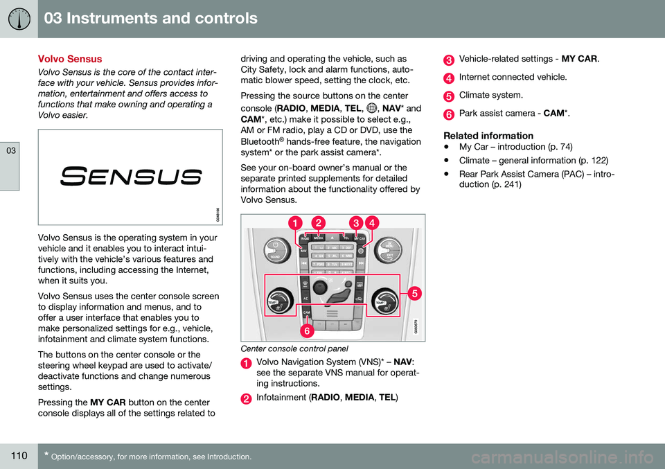
Center console control panel
Volvo Navigation System (VNS)* – NAV:
see the separate VNS manual for operat- ing instructions.
Infotainment ( RADIO, MEDIA , TEL )
Vehicle-related settings - MY CAR.
Internet connected vehicle.
Climate system.
Park assist camera - CAM*.
Related information
•My Car – introduction (p. 74)
• Climate – general information (p. 122)
• Rear Park Assist Camera (PAC) – intro- duction (p. 241)
Page 115 of 402
03 Instruments and controls
03
113
Related information
•Information displays – introduction (p. 66)
• Information display – menu overview (p. 111)
• Information display – menu controls(p. 111)
Trip computer – introduction
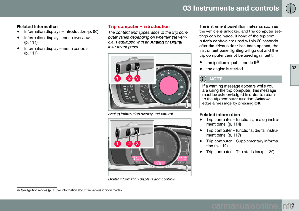
The content and appearance of the trip com- puter varies depending on whether the vehi-cle is equipped with an
Analog or Digital
instrument panel.
Analog information display and controls
Digital information displays and controls The instrument panel illuminates as soon as the vehicle is unlocked and trip computer set-tings can be made. If none of the trip com-puter's controls are used within 30 secondsafter the driver's door has been opened, theinstrument panel lighting will go out and thetrip computer cannot be used again until: •
the ignition is put in mode II25
• the engine is started
NOTE
If a warning message appears while you are using the trip computer, this messagemust be acknowledged in order to returnto the trip computer function. Acknowl-edge a message by pressing
OK.
Related information
• Trip computer – functions, analog instru- ment panel (p. 114)
• Trip computer – functions, digital instru-ment panel (p. 117)
• Trip computer – Supplementary informa-tion (p. 119)
• Trip computer – Trip statistics (p. 120)
25
See Ignition modes (p. 77) for information about the various ignition modes.
Page 124 of 402

04 Climate
04
122* Option/accessory, for more information, see Introduction.
Climate – general information
The vehicle is equipped with Electronic Cli- mate Control (ECC) (p. 126) that cools, heatsor dehumidifies the air in the passenger com-partment.
Air conditioning
NOTE
• The air conditioning can be switched off, but to ensure the best possible cli-mate comfort in the passenger com-partment and to prevent the windowsfrom misting, it should always be on.
• In warm weather, a small amount ofwater may accumulate under the carwhen it has been parked. This water iscondensation from the A/C systemand is normal.
Side windows and moonroofTo ensure that the air conditioning works optimally, the side windows, and the optionalmoonroof should be closed.
Fog on the inside of the windowsThe defroster function (p. 129) should beused to remove fog or mist from the inside ofthe windows. Keeping the windows cleanwith a commercially available window wash-ing spray will also help prevent fogging ormisting.
Temporary shut-off of the air conditioning
The air conditioning (p. 129) is momentarily disengaged during full acceleration or whendriving uphill with a trailer. This may result ina temporary increase in cabin temperature.
Ice and snowAlways keep the air intake grille at the base ofthe windshield free of snow.
Climate system maintenanceSpecial tools and equipment are required tomaintain and carry out repairs on the climatesystem. Work of this type should only bedone by a trained and qualified Volvo servicetechnician.
RefrigerantVolvo cares about the environment. The airconditioning system in your car contains aCFC-free refrigerant – R134a. This substancewill not deplete the ozone layer. The air con-ditioning system contains 1.76 lbs (800 g) ofR134a. The systems uses PAG oil.
Related information
•
Climate – sensors (p. 122)
• Climate – menu settings (p. 124)
Climate – sensors
The climate system utilizes a number of sen- sors to help regulate the temperature andhumidity level in the passenger compartment.
Sensor location
• The sunlight sensor is located on the top side of the dashboard.
NOTE
The sunlight sensor monitors which side of the car that is most exposed to sunlight.This can mean that the temperature maydiffer between the right and left-side airvents, even if the temperatures set for bothsides of the passenger compartment arethe same.
•The temperature sensor for the passen- ger compartment is located below the cli-mate control panel.
• The outside (ambient) temperature sensoris located on the door mirror.
• The humidity sensor* is located in theinterior rearview mirror.
NOTE
Do not cover or block the sensors with clothing or other objects.
Related information
•
Climate – general information (p. 122)
Page 130 of 402

04 Climate
04
128
Temperature and blower control
When the vehicle is started, the most recent setting is resumed. The blower should always be activated to help avoid condensation and fogging on thewindows.
Temperature controlThe temperatures on thedriver and passenger sidescan be set separately.
NOTE
Heating or cooling cannot be speeded up by selecting a higher/lower temperaturethan the actual temperature required.
Blower controlTurn the control clockwise to increase or counterclockwiseto decrease the blowerspeed. If AUTO (p. 128) is
selected, blower speed willbe regulated automaticallyand this will override manual
adjustment.
NOTE
If the blower is turned off completely, the air conditioning is disengaged, which mayresult in fogging on the windows.
Related information
• Climate – general information (p. 122)
• Electronic climate control (ECC) (p. 126)
• Air conditioning (p. 129)
• Climate – sensors (p. 122)
Automatic climate control
The Auto function automatically controls tem- perature (p. 128), air conditioning (p. 129),blower speed (p. 128), recirculation (p. 131)and air distribution (p. 124).
If you select one or moremanual functions, the otherfunctions continue to becontrolled automatically. Theair quality (p. 123) sensor isengaged and all manual set-tings are switched off when
AUTO is pressed. The display shows
AUTO
CLIMATE.
Blower speed in automatic mode can be set under
Climate settingsAutomatic blower
adjustment
. Choose between Low, Normalor High.
NOTE
Selecting the lowest blower speed may increases the risk of fog forming on thewindows.
Related information
• Climate – general information (p. 122)
Page 140 of 402
05 Loading and storage
05
138* Option/accessory, for more information, see Introduction.
Glove compartment
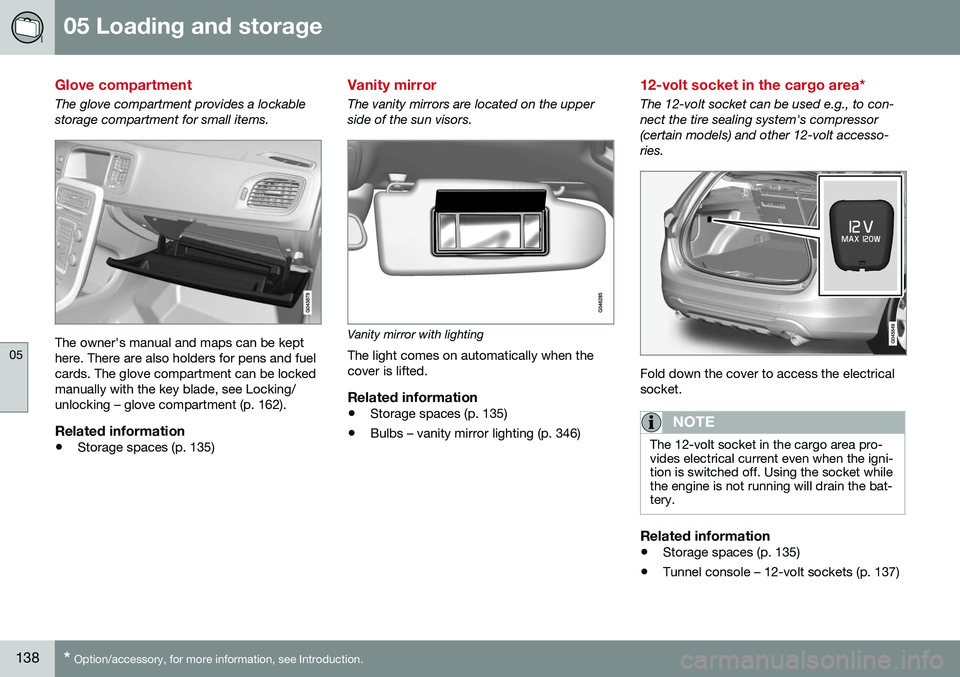
The glove compartment provides a lockable storage compartment for small items.
The owner's manual and maps can be kept here. There are also holders for pens and fuelcards. The glove compartment can be lockedmanually with the key blade, see Locking/unlocking – glove compartment (p. 162).
Related information
• Storage spaces (p. 135)
Vanity mirror
The vanity mirrors are located on the upper side of the sun visors.
Vanity mirror with lighting
The light comes on automatically when the cover is lifted.
Related information
• Storage spaces (p. 135)
• Bulbs – vanity mirror lighting (p. 346)
12-volt socket in the cargo area*
The 12-volt socket can be used e.g., to con- nect the tire sealing system's compressor(certain models) and other 12-volt accesso-ries.
Fold down the cover to access the electrical socket.
NOTE
The 12-volt socket in the cargo area pro- vides electrical current even when the igni-tion is switched off. Using the socket whilethe engine is not running will drain the bat-tery.
Related information
• Storage spaces (p. 135)
• Tunnel console – 12-volt sockets (p. 137)
Page 144 of 402
||
05 Loading and storage
05
142
Using the net(s)
G018246
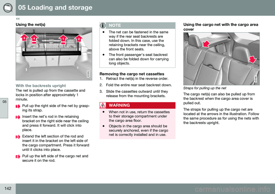
With the backrests uprightThe net is pulled up from the cassette and locks in position after approximately 1minute.
Pull up the right side of the net by grasp- ing its strap.
Insert the net’s rod in the retaining bracket on the right side near the ceilingand press it forward. It will click intoplace.
Extend the left section of the rod and insert it in the bracket on the left side ofthe cargo compartment. Press it forwarduntil it clicks into place.
Pull up the left side of the cargo net and secure it on the rod.
NOTE
•The net can be fastened in the same way if the rear seat backrests arefolded down. In this case, use theretaining brackets near the ceiling,above the front seats.
• The front passenger's seat backrestcan also be folded down for carryinglong objects.
Removing the cargo net cassettes1. Retract the net(s) in the reverse order.
2. Fold the entire rear seat backrest down.
3. Slide the cassettes outward until they
release from the mounting brackets.
WARNING
•When not in use, return the cassettes to their storage compartment underthe cargo area floor.
• Objects in the cargo area should besecurely anchored, even if the cargonet is correctly installed and in use.
Using the cargo net with the cargo area cover
Straps for pulling up the net
The cargo net(s) can also be pulled up from the backrest when the cargo area cover ispulled out. The straps for pulling up the cargo net are located at the arrows in the illustration. Followthe same procedure as for using the nets withthe backrests upright.
Page 145 of 402
05 Loading and storage
05
}}
143
Cargo area cover
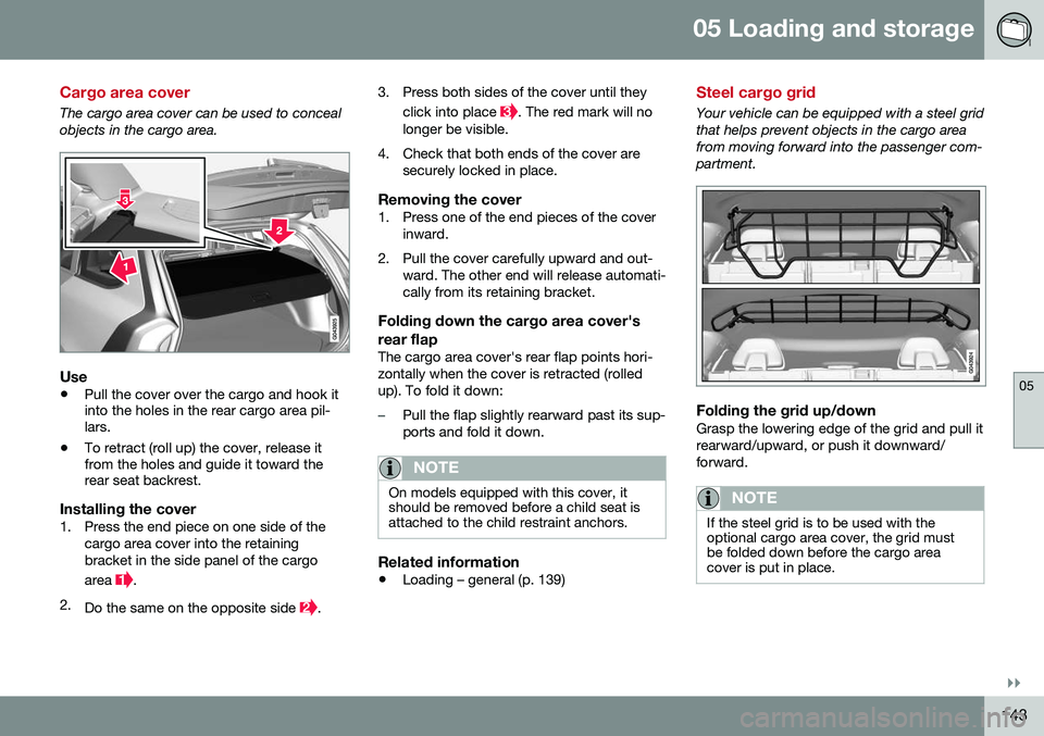
The cargo area cover can be used to conceal objects in the cargo area.
Use
•Pull the cover over the cargo and hook it into the holes in the rear cargo area pil-lars.
• To retract (roll up) the cover, release itfrom the holes and guide it toward therear seat backrest.
Installing the cover1. Press the end piece on one side of the
cargo area cover into the retaining bracket in the side panel of the cargo area
.
2. Do the same on the opposite side
. 3. Press both sides of the cover until they
click into place
. The red mark will no
longer be visible.
4. Check that both ends of the cover are securely locked in place.
Removing the cover1. Press one of the end pieces of the coverinward.
2. Pull the cover carefully upward and out- ward. The other end will release automati- cally from its retaining bracket.
Folding down the cargo area cover's rear flap
The cargo area cover's rear flap points hori- zontally when the cover is retracted (rolledup). To fold it down:
–Pull the flap slightly rearward past its sup- ports and fold it down.
NOTE
On models equipped with this cover, it should be removed before a child seat isattached to the child restraint anchors.
Related information
• Loading – general (p. 139)
Steel cargo grid
Your vehicle can be equipped with a steel grid that helps prevent objects in the cargo areafrom moving forward into the passenger com-partment.
Folding the grid up/downGrasp the lowering edge of the grid and pull it rearward/upward, or push it downward/forward.
NOTE
If the steel grid is to be used with the optional cargo area cover, the grid mustbe folded down before the cargo areacover is put in place.
Page 148 of 402
06 Locks and alarm
06
146
Remote key and key blade
Two remote keys are provided with your vehi- cle. They enable you to unlock the doors andtailgate, and also function as ignition keys tostart the vehicle or operate electrical compo-nents. The remote keys contain detachablemetal key blades for manually locking orunlocking the driver's door and the glovecompartment. The visible ends of these keyblades are unique to make it easier to identify"your" remote key. Up to six remotes can beprogrammed for use on the same vehicle.
WARNING
Never leave the remote key in the ignition slot if children are to remain in the vehicle.
For more information on the various ignition modes, see Ignition modes (p. 77).
Related information
•Remote key – functions (p. 149)
• Remote key – functions (p. 149)
• Remote key – range (p. 150)
Remote key – loss
If either of the remote keys (p. 146) is lost, the other should be taken with the vehicle to aVolvo retailer. As an anti-theft measure, thecode of the lost remote key must be erasedfrom the system.
NOTE
Additional or duplicate remote control keys can be obtained from any authorized Volvoretailer. You can also obtain additional or duplicate remote control keys from certain inde-pendent repair facilities and locksmithsthat are qualified to make remote controlkeys. Each key must be programmed towork with your vehicle. California Only: A list of independent repair facilities and/or locksmiths known to Volvo that can cutand code replacement keys can be found:
• on the Volvo website at http://www.volvocars.com/us/keys
• by calling Volvo Customer Care at1-800-458-1552
The number of registered keys for the vehicle can be found by pressing
MY CAR and going
into
SettingsInformationNumber of
keys. For a description of the menu system,
see My Car – introduction (p. 74). USA-5WK49264 FCC ID:KR55WK49264 + Siemens VDO 5WK49236 FCC ID:KR55WK49236, 5WK49266FCC ID:KR55WK49266 + Siemens VDO 5WK49233 FCC ID:KR55WK49233This device complies with part 15 of the FCC rules and RSS-210. Operation is subject tothe following conditions: (1) This device maynot cause harmful interference, and (2) thisdevice must accept any interferencereceived, including interference that maycause undesired operation. Canada-5WK49264IC:267T-5WK49264 + Siemens VDO 5WK49236 IC:267T-5WK49236, 5WK49266IC:267T-5WK49266 + Siemens VDO 5WK49233 IC:267T-5WK49233Operation is subject to the following condi- tions: (1) this device may not cause interfer-ence, and (2) this device must accept anyinterference, including interference that maycause undesired operation of the device.Related information
•
Remote key – functions (p. 149)