2016 VOLVO V60 CROSS COUNTRY light
[x] Cancel search: lightPage 129 of 402
04 Climate
04
* Option/accessory, for more information, see Introduction.127
Heated seats
The front seat heating has three levels to increase comfort for the driver and passengerin cold weather. The rear outboard seat heating has three lev- els to increase comfort for the passengers incold weather.
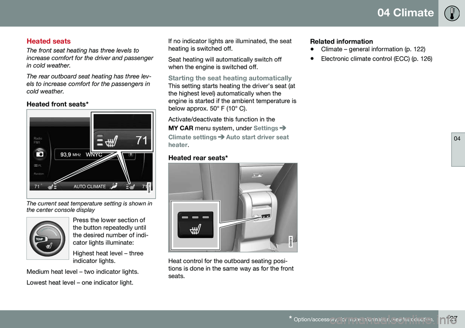
Heated front seats*
The current seat temperature setting is shown in the center console display
Press the lower section of the button repeatedly untilthe desired number of indi-cator lights illuminate: Highest heat level – three indicator lights.
Medium heat level – two indicator lights. Lowest heat level – one indicator light.
If no indicator lights are illuminated, the seat heating is switched off. Seat heating will automatically switch off when the engine is switched off.
Starting the seat heating automaticallyThis setting starts heating the driver's seat (at the highest level) automatically when theengine is started if the ambient temperature isbelow approx. 50° F (10° C). Activate/deactivate this function in the MY CAR menu system, under
Settings
Climate settingsAuto start driver seat
heater.
Heated rear seats*
Heat control for the outboard seating posi- tions is done in the same way as for the frontseats.
Related information
• Climate – general information (p. 122)
• Electronic climate control (ECC) (p. 126)
Page 131 of 402
04 Climate
04
}}
* Option/accessory, for more information, see Introduction.129
Air conditioning
The air conditioning function cools and dehu- midifies the air in the passenger compart-ment.
When the indicator light inthe button is on, the air con-ditioning is controlled auto-matically. This cools/heatsand dehumidifies the incom-ing air. When the indicatorlight in the button is off, the
air conditioning is disengaged. Other func-tions are still controlled automatically. Whenmaximum defroster (p. 129) is selected, theair conditioning system is set for maximumblower speed and dehumidifies the cabin asquickly as possible.
Related information
• Climate – general information (p. 122)
• Automatic climate control (p. 128)
Max. defroster and electrically heated windshield*
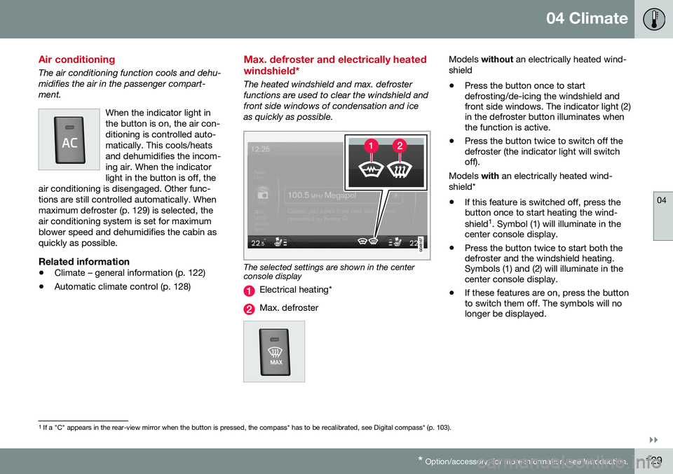
The heated windshield and max. defroster functions are used to clear the windshield andfront side windows of condensation and iceas quickly as possible.
The selected settings are shown in the center console display
Electrical heating*
Max. defroster
Models
without an electrically heated wind-
shield • Press the button once to start defrosting/de-icing the windshield andfront side windows. The indicator light (2)in the defroster button illuminates whenthe function is active.
• Press the button twice to switch off thedefroster (the indicator light will switchoff).
Models with an electrically heated wind-
shield*
• If this feature is switched off, press thebutton once to start heating the wind- shield 1
. Symbol (1) will illuminate in the
center console display.
• Press the button twice to start both the defroster and the windshield heating.Symbols (1) and (2) will illuminate in thecenter console display.
• If these features are on, press the buttonto switch them off. The symbols will nolonger be displayed.
1
If a "C" appears in the rear-view mirror when the button is pressed, the compass* has to be recalibrated, see Digital compass* (p. 103).
Page 132 of 402
||
04 Climate
04
130* Option/accessory, for more information, see Introduction.
NOTE
• Triangular areas at the far sides of the windshield are not heated electricallyand will take slightly longer todefrost/de-ice.
• The heated windshield may affect theperformance/range of e.g., transpond-ers used to automatically pay highwaytolls or other communication equip-ment.
The following occurs when the defroster/ windshield heating functions have been acti-vated: •
Blower speed increases automatically and the air conditioning (p. 129) willswitch on (if not already on and if the pas-senger compartment blower is not turnedoff) to dehumidify the air in the passengercompartment. Air conditioning can beswitched off by pressing the
AC button.
• Recirculation (p. 131) will not functionwhile defrost is engaged.
The climate system will return to its previous
settings when the defroster/windshield heat- ing function is switched off. See also Heated windshield*, rear window and door mirror defrosters (p. 102) for addi-tional information.
Related information
• Climate – general information (p. 122)
• Automatic climate control (p. 128)
Air distribution – function
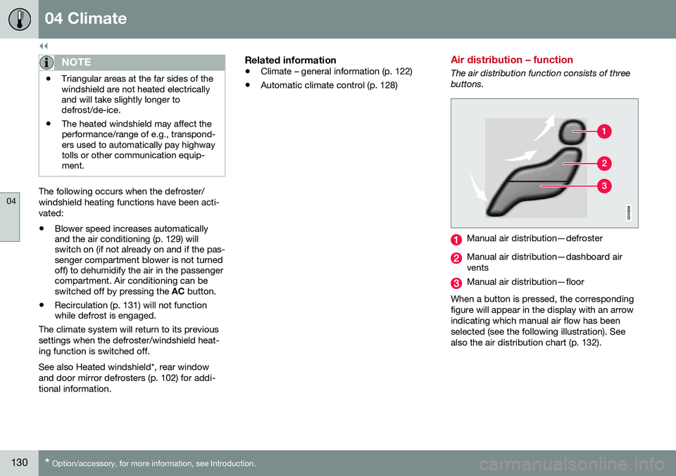
The air distribution function consists of three buttons.
Manual air distribution—defroster
Manual air distribution—dashboard air vents
Manual air distribution—floor
When a button is pressed, the corresponding figure will appear in the display with an arrowindicating which manual air flow has beenselected (see the following illustration). Seealso the air distribution chart (p. 132).
Page 133 of 402
04 Climate
04
131
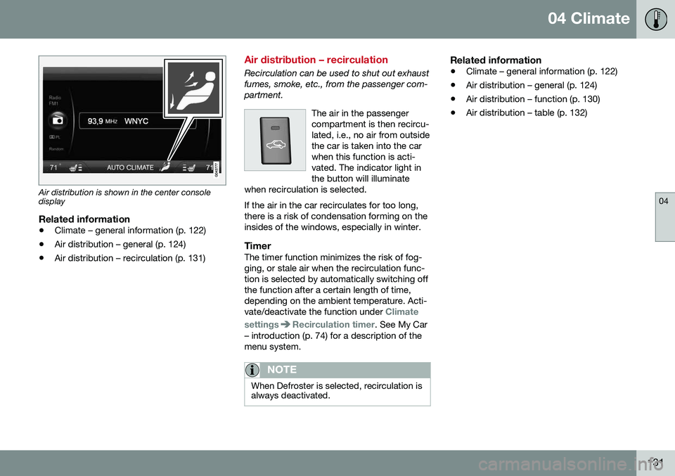
Air distribution is shown in the center console display
Related information
•Climate – general information (p. 122)
• Air distribution – general (p. 124)
• Air distribution – recirculation (p. 131)
Air distribution – recirculation
Recirculation can be used to shut out exhaust fumes, smoke, etc., from the passenger com-partment.
The air in the passengercompartment is then recircu-lated, i.e., no air from outsidethe car is taken into the carwhen this function is acti-vated. The indicator light inthe button will illuminate
when recirculation is selected. If the air in the car recirculates for too long, there is a risk of condensation forming on theinsides of the windows, especially in winter.
TimerThe timer function minimizes the risk of fog- ging, or stale air when the recirculation func-tion is selected by automatically switching offthe function after a certain length of time,depending on the ambient temperature. Acti-vate/deactivate the function under
Climate
settings
Recirculation timer. See My Car
– introduction (p. 74) for a description of the menu system.
NOTE
When Defroster is selected, recirculation is always deactivated.
Related information
• Climate – general information (p. 122)
• Air distribution – general (p. 124)
• Air distribution – function (p. 130)
• Air distribution – table (p. 132)
Page 139 of 402
05 Loading and storage
05
* Option/accessory, for more information, see Introduction.137
Tunnel console
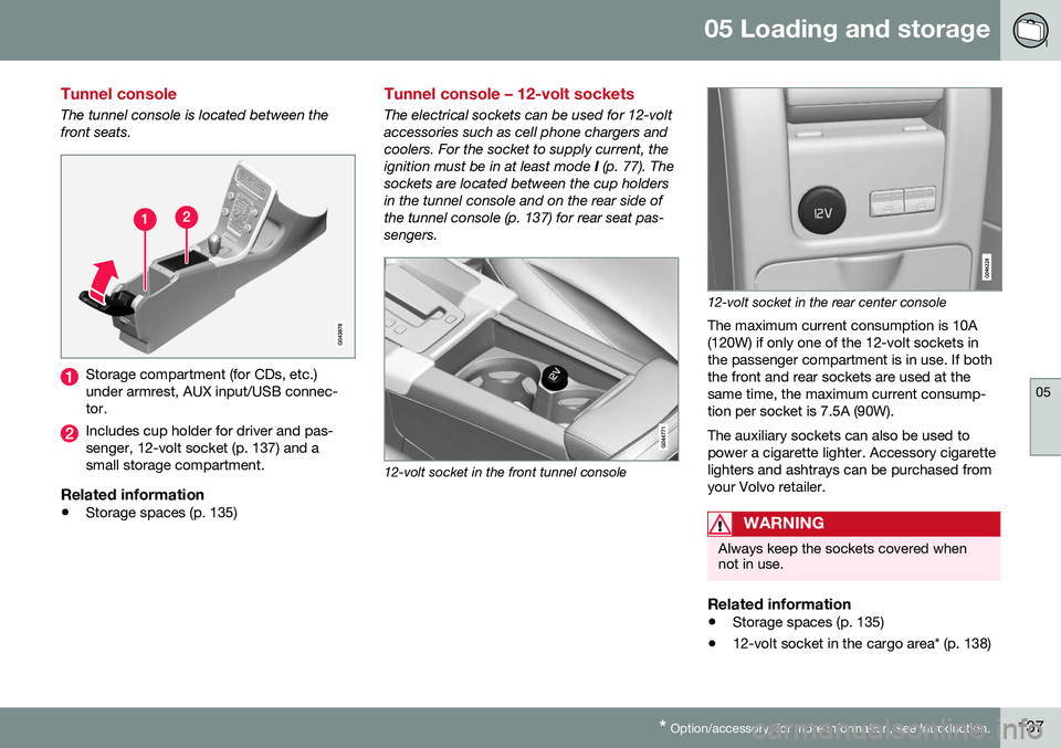
The tunnel console is located between the front seats.
Storage compartment (for CDs, etc.) under armrest, AUX input/USB connec-tor.
Includes cup holder for driver and pas- senger, 12-volt socket (p. 137) and asmall storage compartment.
Related information
• Storage spaces (p. 135)
Tunnel console – 12-volt sockets
The electrical sockets can be used for 12-volt accessories such as cell phone chargers andcoolers. For the socket to supply current, theignition must be in at least mode
I (p. 77). The
sockets are located between the cup holdersin the tunnel console and on the rear side ofthe tunnel console (p. 137) for rear seat pas-sengers.
12-volt socket in the front tunnel console
12-volt socket in the rear center console
The maximum current consumption is 10A (120W) if only one of the 12-volt sockets inthe passenger compartment is in use. If boththe front and rear sockets are used at thesame time, the maximum current consump-tion per socket is 7.5A (90W). The auxiliary sockets can also be used to power a cigarette lighter. Accessory cigarettelighters and ashtrays can be purchased fromyour Volvo retailer.
WARNING
Always keep the sockets covered when not in use.
Related information
• Storage spaces (p. 135)
• 12-volt socket in the cargo area* (p. 138)
Page 140 of 402
05 Loading and storage
05
138* Option/accessory, for more information, see Introduction.
Glove compartment
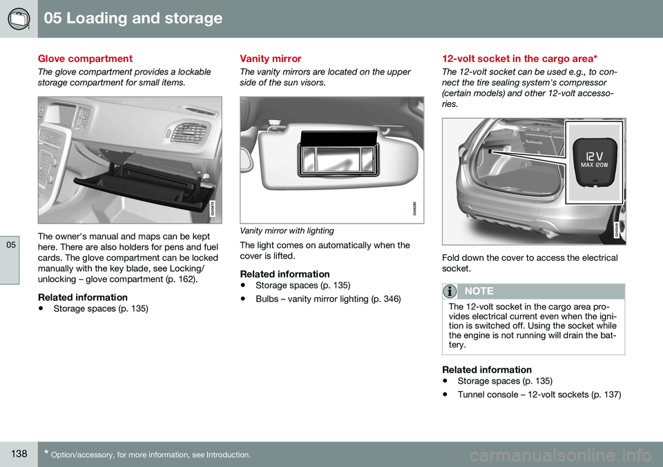
The glove compartment provides a lockable storage compartment for small items.
The owner's manual and maps can be kept here. There are also holders for pens and fuelcards. The glove compartment can be lockedmanually with the key blade, see Locking/unlocking – glove compartment (p. 162).
Related information
• Storage spaces (p. 135)
Vanity mirror
The vanity mirrors are located on the upper side of the sun visors.
Vanity mirror with lighting
The light comes on automatically when the cover is lifted.
Related information
• Storage spaces (p. 135)
• Bulbs – vanity mirror lighting (p. 346)
12-volt socket in the cargo area*
The 12-volt socket can be used e.g., to con- nect the tire sealing system's compressor(certain models) and other 12-volt accesso-ries.
Fold down the cover to access the electrical socket.
NOTE
The 12-volt socket in the cargo area pro- vides electrical current even when the igni-tion is switched off. Using the socket whilethe engine is not running will drain the bat-tery.
Related information
• Storage spaces (p. 135)
• Tunnel console – 12-volt sockets (p. 137)
Page 145 of 402
05 Loading and storage
05
}}
143
Cargo area cover
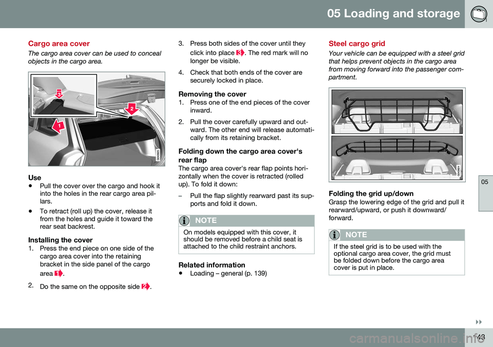
The cargo area cover can be used to conceal objects in the cargo area.
Use
•Pull the cover over the cargo and hook it into the holes in the rear cargo area pil-lars.
• To retract (roll up) the cover, release itfrom the holes and guide it toward therear seat backrest.
Installing the cover1. Press the end piece on one side of the
cargo area cover into the retaining bracket in the side panel of the cargo area
.
2. Do the same on the opposite side
. 3. Press both sides of the cover until they
click into place
. The red mark will no
longer be visible.
4. Check that both ends of the cover are securely locked in place.
Removing the cover1. Press one of the end pieces of the coverinward.
2. Pull the cover carefully upward and out- ward. The other end will release automati- cally from its retaining bracket.
Folding down the cargo area cover's rear flap
The cargo area cover's rear flap points hori- zontally when the cover is retracted (rolledup). To fold it down:
–Pull the flap slightly rearward past its sup- ports and fold it down.
NOTE
On models equipped with this cover, it should be removed before a child seat isattached to the child restraint anchors.
Related information
• Loading – general (p. 139)
Steel cargo grid
Your vehicle can be equipped with a steel grid that helps prevent objects in the cargo areafrom moving forward into the passenger com-partment.
Folding the grid up/downGrasp the lowering edge of the grid and pull it rearward/upward, or push it downward/forward.
NOTE
If the steel grid is to be used with the optional cargo area cover, the grid mustbe folded down before the cargo areacover is put in place.
Page 150 of 402
||
06 Locks and alarm
06
148
Making a settingDifferent alternatives for locking/unlocking confirmation can be selected in the menus bypressing MY CAR on the center console con-
trol panel. • To activate visual confirmation: go to
SettingsCar settingsLight
settings and select Door lock
confirmation light and/or Unlock
confirmation light by pressing OK/
MENU .
• To activate audible confirmation: go to
SettingsCar settingsLock
settings and select Audible
confirmation by pressing OK/MENU.
For a description of the menu system, see My Car – introduction (p. 74).
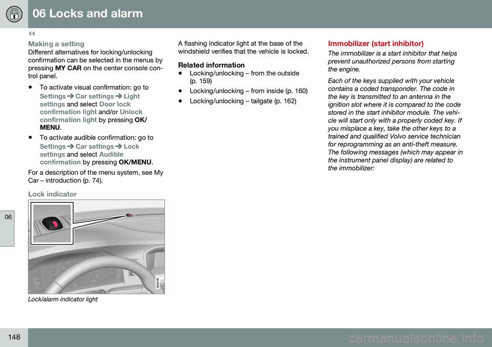
Lock indicator
Lock/alarm indicator light A flashing indicator light at the base of the windshield verifies that the vehicle is locked.
Related information
•
Locking/unlocking – from the outside (p. 159)
• Locking/unlocking – from inside (p. 160)
• Locking/unlocking – tailgate (p. 162)
Immobilizer (start inhibitor)
The immobilizer is a start inhibitor that helps prevent unauthorized persons from startingthe engine. Each of the keys supplied with your vehicle contains a coded transponder. The code inthe key is transmitted to an antenna in theignition slot where it is compared to the codestored in the start inhibitor module. The vehi-cle will start only with a properly coded key. Ifyou misplace a key, take the other keys to atrained and qualified Volvo service technicianfor reprogramming as an anti-theft measure.The following messages (which may appear inthe instrument panel display) are related tothe immobilizer: