2016 VOLVO V60 CROSS COUNTRY turn signal
[x] Cancel search: turn signalPage 242 of 402

||
07 Driver support
07
240* Option/accessory, for more information, see Introduction.
The sensors must be cleaned regularly to ensure that they work properly. Clean themwith water and a suitable car washing deter-gent.
Related information
• Park Assist Pilot (PAP)* – introduction (p. 236)
• Park Assist Pilot (PAP)* – function (p. 236)
• Park Assist Pilot (PAP)* – operation(p. 237)
• Park Assist Pilot (PAP)* – symbols andmessages (p. 240)
• Park assist – introduction (p. 232)
• Rear Park Assist Camera (PAC) – intro-duction (p. 241)
Park Assist Pilot (PAP)* – symbols and messages
Various PAP-related combinations of sym- bols, graphics and text messages are dis-played in the instrument panel and some-times also include suitable actions. A text message can be erased by pressing briefly on the
OK button on the turn signal
lever. Contact a Volvo retailer or a trained and qualified Volvo service technician If a mes-sage indicating that PAP is not functioningproperly is displayed.
Related information
• Park Assist Pilot (PAP)* – introduction (p. 236)
• Park Assist Pilot (PAP)* – function (p. 236)
• Park Assist Pilot (PAP)* – operation(p. 237)
• Park Assist Pilot (PAP)* – limitations(p. 239)
• Park assist – introduction (p. 232)
• Rear Park Assist Camera (PAC) – intro-duction (p. 241)
Park assist – troubleshooting
Faults in the systemIf the information symbol illuminates andPark assist syst Service required is shown
on the information display, this indicates that the system is not functioning properly andhas been disengaged. Consult a trained andqualified Volvo service technician.
CAUTION
In certain circumstances, the park assist system may give unexpected warning sig-nals that can be caused by external soundsources that use the same ultrasound fre-quencies as the system. This may includesuch things as the horns of other vehicles,wet tires on asphalt, pneumatic brakes,motorcycle exhaust pipes, etc. This doesnot indicate a fault in the system.
Related information
• Park assist – introduction (p. 232)
• Park assist – limitations (p. 235)
• Park assist – function (p. 232)
• Park assist – operation (p. 234)
• Rear Park Assist Camera (PAC) – function (p. 241)
Page 248 of 402
||
07 Driver support
07
246* Option/accessory, for more information, see Introduction.
WARNING
• BLIS and CTA are information sys- tems, NOT warning or safety systemsand do not function in all situations.
• BLIS and CTA do not eliminate theneed for you to visually confirm theconditions around you, and the needfor you to turn your head and should-ers to make sure that you can safelychange lanes or back up.
• As the driver, you have full responsibil-ity for changing lanes/backing up in asafe manner.
Related information
•
BLIS* – function (p. 246)
• BLIS* – operation (p. 247)
• BLIS* – Cross Traffic Alert (CTA) (p. 247)
• BLIS* – limitations (p. 249)
• BLIS* – messages (p. 250)
BLIS* – function
When does BLIS functionThe system functions when your vehicle is moving at speeds above 6 mph (10 km/h).
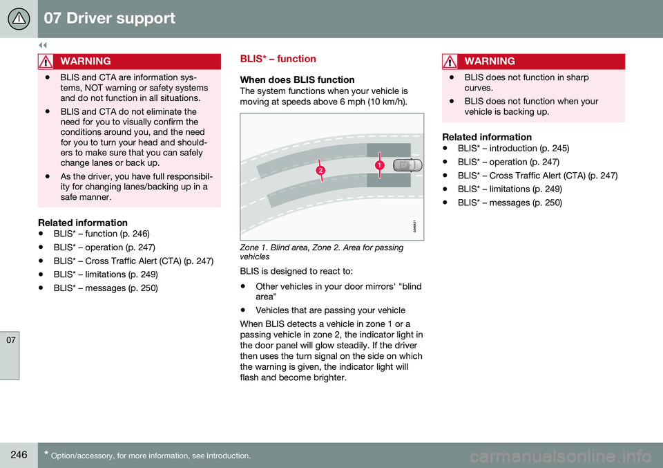
Zone 1. Blind area, Zone 2. Area for passing vehicles
BLIS is designed to react to:
• Other vehicles in your door mirrors' "blind area"
• Vehicles that are passing your vehicle
When BLIS detects a vehicle in zone 1 or a passing vehicle in zone 2, the indicator light inthe door panel will glow steadily. If the driverthen uses the turn signal on the side on whichthe warning is given, the indicator light willflash and become brighter.
WARNING
• BLIS does not function in sharp curves.
• BLIS does not function when yourvehicle is backing up.
Related information
•
BLIS* – introduction (p. 245)
• BLIS* – operation (p. 247)
• BLIS* – Cross Traffic Alert (CTA) (p. 247)
• BLIS* – limitations (p. 249)
• BLIS* – messages (p. 250)
Page 250 of 402

||
07 Driver support
07
248
WARNING
•BLIS and CTA are information sys- tems, NOT warning or safety systemsand do not function in all situations.
• BLIS and CTA do not eliminate theneed for you to visually confirm theconditions around you, and the needfor you to turn your head and should-ers to make sure that you can safelychange lanes or back up.
• As the driver, you have full responsibil-ity for changing lanes/backing up in asafe manner.
When does CTA function
How CTA works
CTA supplements BLIS by warning the driver of crossing traffic behind your vehicle, for example, when backing out of a parkingspace. It is primarily designed to detect another vehi- cle but in certain cases may also detectpedestrians or smaller objects such as bicy-cles. CTA is only activated when the vehicle is backing up and is activated automaticallywhen the gear selector is put in reverse.
• An audible signal indicates that CTA has detected something that is approachingfrom the side. The signal will come fromeither the left or right audio systemspeakers, depending on which the side ofyour vehicle the approaching vehicle/object has been detected.
• CTA also provides a warning by illuminat-ing the BLIS indicator lights.
• An icon will also illuminate in the Parkassist graphic on the center console dis-play.
LimitationsCTA has limitations in certain situations, for example, the CTA sensors cannot "see"through other parked vehicles or obstruc-tions. The following are several examples where CTA's "field of vision" may initially be limitedand approaching vehicles cannot be detecteduntil they are too close:
The vehicle is pulled far into a parking space
CTA's blind area
CTA's "field of vision"
In angled parking spaces, CTA may be "blind" on one side
15
Blind Spot Information System
Page 257 of 402
08 Starting and driving
08
* Option/accessory, for more information, see Introduction.255
Engine Remote Start (ERS)* – starting the engine
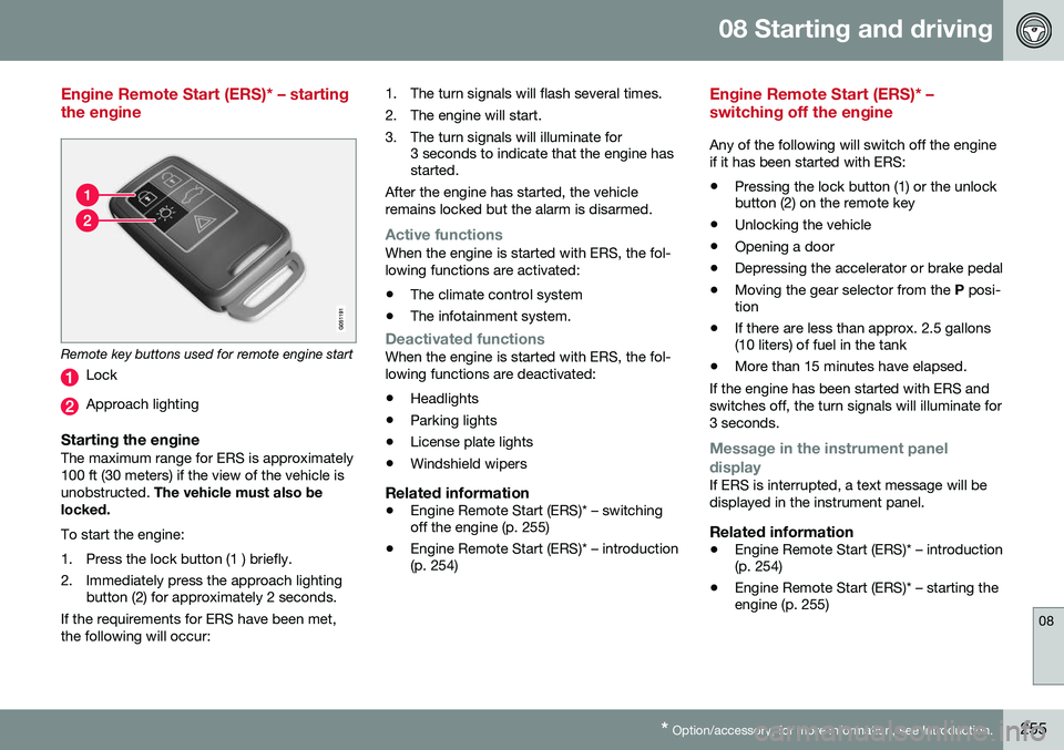
Remote key buttons used for remote engine start
Lock
Approach lighting
Starting the engineThe maximum range for ERS is approximately 100 ft (30 meters) if the view of the vehicle isunobstructed. The vehicle must also be
locked. To start the engine:
1. Press the lock button (1 ) briefly.
2. Immediately press the approach lighting button (2) for approximately 2 seconds.
If the requirements for ERS have been met, the following will occur: 1. The turn signals will flash several times.
2. The engine will start.
3. The turn signals will illuminate for
3 seconds to indicate that the engine has started.
After the engine has started, the vehicle remains locked but the alarm is disarmed.
Active functionsWhen the engine is started with ERS, the fol- lowing functions are activated: • The climate control system
• The infotainment system.
Deactivated functionsWhen the engine is started with ERS, the fol- lowing functions are deactivated: •Headlights
• Parking lights
• License plate lights
• Windshield wipers
Related information
•
Engine Remote Start (ERS)* – switching off the engine (p. 255)
• Engine Remote Start (ERS)* – introduction(p. 254)
Engine Remote Start (ERS)* – switching off the engine
Any of the following will switch off the engine if it has been started with ERS:
• Pressing the lock button (1) or the unlock button (2) on the remote key
• Unlocking the vehicle
• Opening a door
• Depressing the accelerator or brake pedal
• Moving the gear selector from the
P posi-
tion
• If there are less than approx. 2.5 gallons(10 liters) of fuel in the tank
• More than 15 minutes have elapsed.
If the engine has been started with ERS and switches off, the turn signals will illuminate for3 seconds.
Message in the instrument panel
display
If ERS is interrupted, a text message will be displayed in the instrument panel.
Related information
• Engine Remote Start (ERS)* – introduction (p. 254)
• Engine Remote Start (ERS)* – starting theengine (p. 255)
Page 277 of 402
08 Starting and driving
08
275
Connect an auxiliary battery if the battery voltage is too low, see Jump starting (p. 256).
Parking on a hill
•
If the vehicle is pointing uphill, turn the front wheels so that they point away fromthe curb.
• If the vehicle is pointing downhill, turn thefront wheels so that they point toward thecurb.
The parking brake should also be applied.
Related information
• Parking brake – applying (p. 275)
• Parking brake – releasing (p. 276)
• Parking brake – symbols and messages(p. 277)
• Brakes – general (p. 271)
Parking brake – applying
Applying the electric parking brake
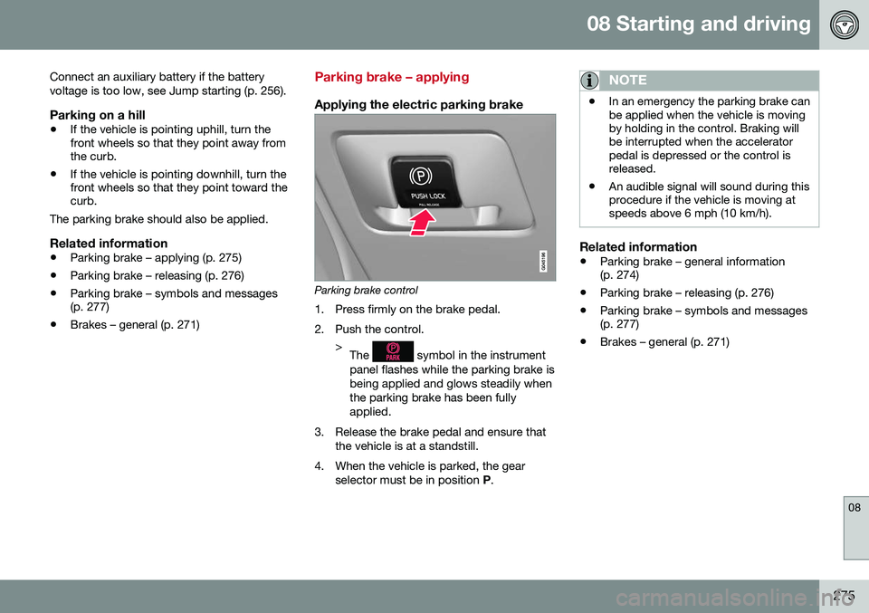
Parking brake control
1. Press firmly on the brake pedal.
2. Push the control. >The
symbol in the instrument
panel flashes while the parking brake is being applied and glows steadily whenthe parking brake has been fullyapplied.
3. Release the brake pedal and ensure that the vehicle is at a standstill.
4. When the vehicle is parked, the gear selector must be in position P.
NOTE
• In an emergency the parking brake can be applied when the vehicle is movingby holding in the control. Braking willbe interrupted when the acceleratorpedal is depressed or the control isreleased.
• An audible signal will sound during thisprocedure if the vehicle is moving atspeeds above 6 mph (10 km/h).
Related information
•
Parking brake – general information (p. 274)
• Parking brake – releasing (p. 276)
• Parking brake – symbols and messages(p. 277)
• Brakes – general (p. 271)
Page 279 of 402
08 Starting and driving
08
277
Parking brake – symbols and messages
A text message can be erased by pressing briefly on the OK button on the turn signal
lever.
Symbol and messages in the instrument panel
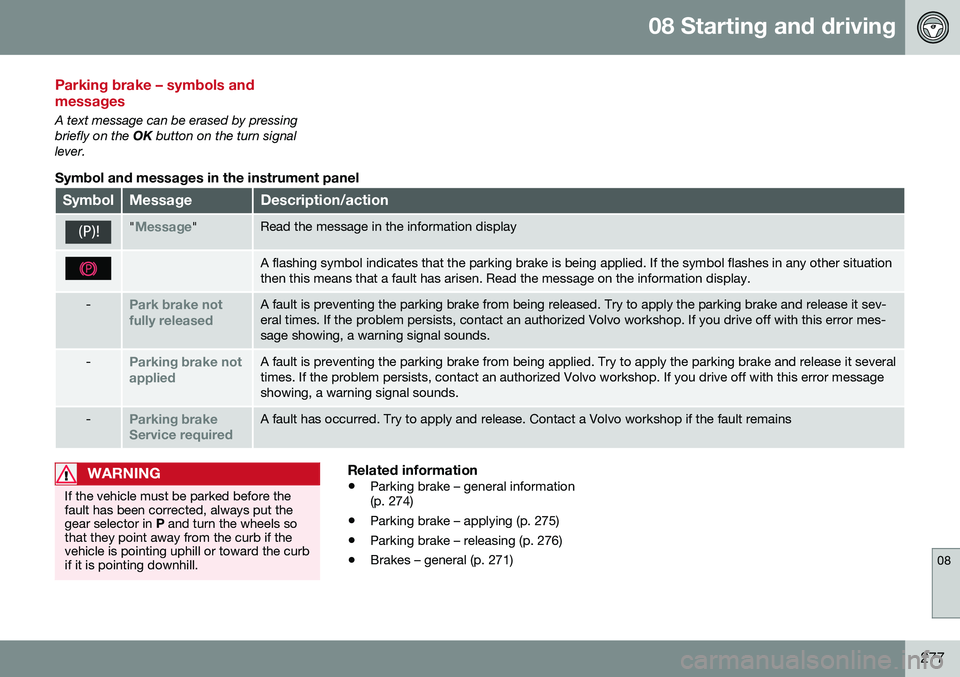
SymbolMessageDescription/action
"Message"Read the message in the information display
A flashing symbol indicates that the parking brake is being applied. If the symbol flashes in any other situation then this means that a fault has arisen. Read the message on the information display.
-Park brake not fully releasedA fault is preventing the parking brake from being released. Try to apply the parking brake and release it sev- eral times. If the problem persists, contact an authorized Volvo workshop. If you drive off with this error mes-sage showing, a warning signal sounds.
-Parking brake not appliedA fault is preventing the parking brake from being applied. Try to apply the parking brake and release it several times. If the problem persists, contact an authorized Volvo workshop. If you drive off with this error messageshowing, a warning signal sounds.
-Parking brake Service requiredA fault has occurred. Try to apply and release. Contact a Volvo workshop if the fault remains
WARNING
If the vehicle must be parked before the fault has been corrected, always put thegear selector in P and turn the wheels so
that they point away from the curb if thevehicle is pointing uphill or toward the curbif it is pointing downhill.
Related information
• Parking brake – general information (p. 274)
• Parking brake – applying (p. 275)
• Parking brake – releasing (p. 276)
• Brakes – general (p. 271)
Page 341 of 402
10 Maintenance and servicing
10
}}
339
CAUTION
Keep the area around the power steering fluid reservoir clean when checking.
Bulbs – introduction
Certain bulbs can be replaced by the vehicle's owner. However, the bulbs on the followinglist should only be replaced by a trained andqualified Volvo service technician. All bulb specifications are listed in Bulbs – specifications (p. 346).• Active Bending Lights
• Front parking lights
• Front side marker lights
• Cornering lights
• Turn signals in the door mirrors
• Approach lighting in the door mirrors
• Interior lighting (except for the front foot- well lighting)
• Rear parking lights/side marker lights
• LED bulbsNOTE
•For information regarding any bulbs not mentioned in this section, pleasecontact your Volvo retailer or a trainedand authorized Volvo service techni-cian.
• Always switch off the ignition beforestarting to replace a bulb.
• If an error message remains in the dis-play after a faulty bulb has beenreplaced, contact an authorized Volvoworkshop.
• Condensation may form temporarily onthe inside of the lenses of exteriorlights such as headlights, fog lights, ortaillights. This is normal and the lightsare designed to withstand moisture.Normally, condensation will dissipateafter the lights have been on for ashort time.
• The optional Active Bending Lightbulbs contain trace amounts of mer-cury. These bulbs should always bedisposed of by a trained and qualifiedVolvo service technician.
Page 346 of 402
10 Maintenance and servicing
10
344
Bulbs – front turn signals
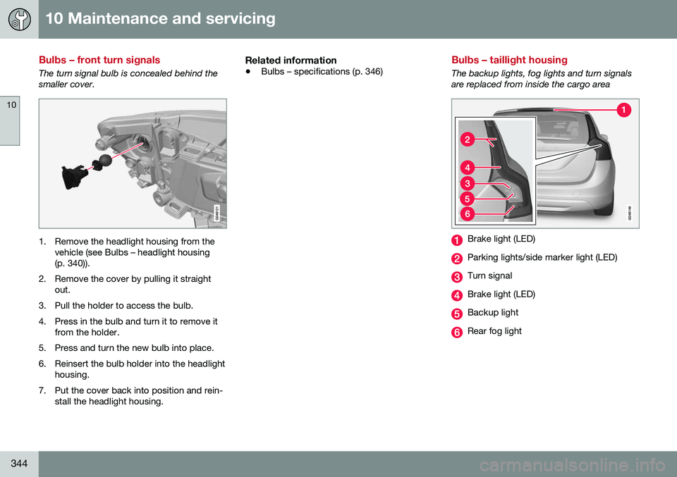
The turn signal bulb is concealed behind the smaller cover.
1. Remove the headlight housing from thevehicle (see Bulbs – headlight housing (p. 340)).
2. Remove the cover by pulling it straight out.
3. Pull the holder to access the bulb.
4. Press in the bulb and turn it to remove it from the holder.
5. Press and turn the new bulb into place.
6. Reinsert the bulb holder into the headlight housing.
7. Put the cover back into position and rein- stall the headlight housing.
Related information
• Bulbs – specifications (p. 346)
Bulbs – taillight housing
The backup lights, fog lights and turn signals are replaced from inside the cargo area
Brake light (LED)
Parking lights/side marker light (LED)
Turn signal
Brake light (LED)
Backup light
Rear fog light