2016 VOLVO V60 CROSS COUNTRY service
[x] Cancel search: servicePage 61 of 402

02 Safety
02
59
Integrated booster cushion – using
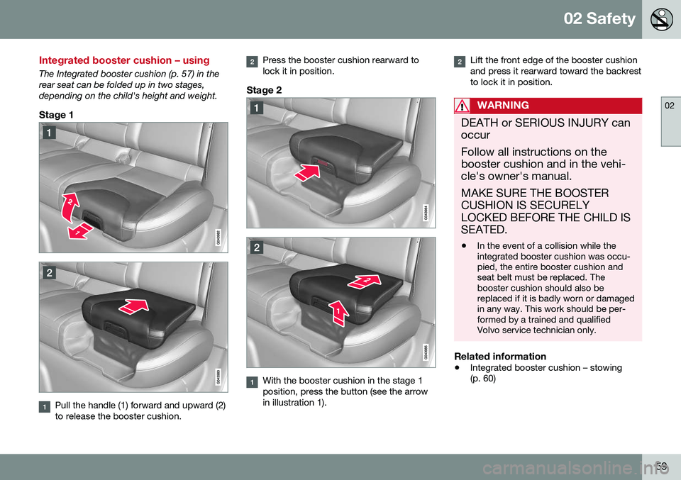
The Integrated booster cushion (p. 57) in the rear seat can be folded up in two stages,depending on the child's height and weight.
Stage 1
Pull the handle (1) forward and upward (2) to release the booster cushion.
Press the booster cushion rearward to lock it in position.
Stage 2
With the booster cushion in the stage 1 position, press the button (see the arrowin illustration 1).
Lift the front edge of the booster cushion and press it rearward toward the backrestto lock it in position.
WARNING
DEATH or SERIOUS INJURY can occur Follow all instructions on the booster cushion and in the vehi-cle's owner's manual. MAKE SURE THE BOOSTER CUSHION IS SECURELYLOCKED BEFORE THE CHILD ISSEATED. •In the event of a collision while the integrated booster cushion was occu-pied, the entire booster cushion andseat belt must be replaced. Thebooster cushion should also bereplaced if it is badly worn or damagedin any way. This work should be per-formed by a trained and qualifiedVolvo service technician only.
Related information
•
Integrated booster cushion – stowing (p. 60)
Page 62 of 402

02 Safety
02
60
Integrated booster cushion – stowing
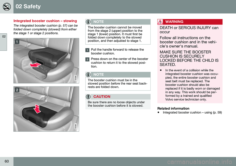
The integrated booster cushion (p. 57) can be folded down completely (stowed) from eitherthe stage 1 or stage 2 positions.NOTE
The booster cushion cannot be moved from the stage 2 (upper) position to thestage 1 (lower) position. It must first befolded down completely to the stowedposition, and then adjusted to stage 1.
Pull the handle forward to release the booster cushion.
Press down on the center of the booster cushion to return it to the stowed posi-tion.
NOTE
The booster cushion must be in the stowed position before the rear seat back-rests are folded down.
CAUTION
Be sure there are no loose objects under the booster cushion before it is stowed.
WARNING
DEATH or SERIOUS INJURY can occur Follow all instructions on the booster cushion and in the vehi-cle's owner's manual. MAKE SURE THE BOOSTER CUSHION IS SECURELYLOCKED BEFORE THE CHILD ISSEATED. •In the event of a collision while the integrated booster cushion was occu-pied, the entire booster cushion andseat belt must be replaced. Thebooster cushion should also bereplaced if it is badly worn or damagedin any way. This work should be per-formed by a trained and qualifiedVolvo service technician only.
Related information
•
Integrated booster cushion – using (p. 59)
Page 73 of 402

03 Instruments and controls
03
}}
* Option/accessory, for more information, see Introduction.71
Malfunction Indicator LightAs you drive, a computer called On-Board Diagnostics II (OBDII) monitors your vehicle'sengine, transmission, electrical and emissionsystems. The malfunction indicator light will illuminate if the computer senses a condition that poten-tially may need correcting. When this hap-pens, please have your vehicle checked by atrained and qualified Volvo service technicianas soon as possible. A malfunction indicator light may have many causes. Sometimes, you may not notice achange in your car's behavior. Even so, anuncorrected condition could hurt fuel econ-omy, emission controls, and drivability.Extended driving without correcting the causecould even damage other components inyour vehicle. This light may illuminate if the fuel filler cap is not closed tightly or if the engine was runningwhile the vehicle was refueled.
Anti-lock Brake System (ABS)If the warning light comes on, there may be a malfunction in the ABS system (the standardbraking system will still function). Check thesystem by:
1. Stopping in a safe place and switching off
the ignition.
2. Restart the engine. 3. If the warning light goes off, no further
action is required.
If the indicator light remains on, the vehicle should be driven to a trained and qualifiedVolvo service technician for inspection, seeBrakes – general (p. 271) for additional infor-mation.
Rear fog lightsThis symbol indicates that the rear fog lights are on.
Stability systemThis indicator symbol flashes when the stabil- ity system is actively working to stabilize thevehicle, see Stability system – introduction(p. 169) for more detailed information.
Stability system - Sport modeThis symbol illuminates to indicate that the stability system's Sport mode has been acti-
vated to help provide maximum tractive force,for example when driving with snow chains,or driving in deep snow or loose sand.
Low fuel levelWhen this light comes on, the vehicle should be refueled as soon as possible. See Refuel-ing – fuel requirements (p. 281) for informa-tion about fuel and refueling.
Information symbolThe information symbol lights up and a text message is displayed to provide the driverwith necessary information about one of thevehicle's systems. The message can beerased and the symbol can be turned off by pressing the
OK button (see Information dis-
play – menu controls (p. 111) for information)or this will take place automatically after ashort time (the length of time varies, depend-ing on the function affected). The information symbol may also illuminate together with other symbols.
High beam indicatorThis symbol illuminates when the high beam headlights are on, or if the high beam flashfunction is used.
Left turn signal indicator
Right turn signal indicator
NOTE
• Both turn signal indicators will flash when the hazard warning flashers areused.
• If either of these indicators flash fasterthan normal, the direction indicatorsare not functioning properly.
Tire pressure monitoring system (TPMS)*
This symbol illuminates to indicate that tire pressure in one or more tires is low, see TirePressure Monitoring System (TPMS) – generalinformation (p. 311) for detailed information.
Eco* function onThe symbol will illuminate when the Eco func- tion is activated.
Page 74 of 402

||
03 Instruments and controls
03
72* Option/accessory, for more information, see Introduction.
Start/stop*The symbol illuminates when the engine has auto-stopped.
Related information
• Information displays – introduction (p. 66)
• Information displays – warning symbols (p. 72)
Information displays – warning symbols
The warning lights alert the driver that an important function is activated or that a seri-ous fault has occurred.
SymbolDescription
Low oil pressure A
Parking brake applied B
SRS airbags
Seat belt reminder
Generator not charging
Fault in the brake system
Warning symbol, read the text displayed in the instrumentpanel
A
Certain engines do not use this symbol to indicate low oil pressure. On these models, a text message will be dis-played on the instrument panel instead, see Engine com-partment – engine oil (p. 334).
B The symbol is Park only on models with the optional digital
instrument panel.
Low oil pressureIf the light comes on while driving, stop the vehicle, stop the engine immediately, andcheck the engine oil level. Add oil if neces- sary. If the oil level is normal and the lightstays on after restart, have the vehicle towedto the nearest trained and qualified Volvoservice technician.
Parking brake appliedThis symbol flashes while the brake is being applied and then glows steadily when theparking brake has been set. See Parking brake – general information (p. 274) for more information about using theparking brake.
Airbags – SRSIf this light comes on while the vehicle is being driven, or remains on for longer thanapproximately 10 seconds after the vehiclehas been started, the SRS system's diagnos-tic functions have detected a fault in a seatbelt lock or pretensioner, a front airbag, sideimpact airbag, and/or an inflatable curtain.Have the system(s) inspected by a trainedand qualified Volvo service technician assoon as possible. See Supplemental Restraint System (SRS) (p. 31) for more information about the airbagsystem.
Seat belt reminderThis symbol comes on for approximately 6 seconds if the driver has not fastened his orher seat belt.
Page 75 of 402

03 Instruments and controls
03
}}
73
Generator not chargingThis symbol comes on during driving if a fault has occurred in the electrical system. Contactan authorized Volvo workshop.
Engine temperatureEngine overheating can result from low oil or coolant levels, towing or hard driving at highheat and altitude, or mechanical malfunction.Engine overheating will be signaled with textand a red warning triangle in the middle of theinstrument display. The exact text will dependon the degree of overheating. It may range from
High engine temp Reduce speed toHigh engine temp Stop engine. If appropri-
ate, other messages, such as Coolant level
low, Stop safely will also be displayed. If
your engine does overheat so that you must stop the engine, always allow the engine tocool before attempting to check oil and cool-ant levels. See Engine compartment – coolant (p. 336) for more information.
Fault in brake systemIf this symbol lights, the brake fluid level may be too low. Stop the vehicle in a safe placeand check the level in the brake fluid reser-voir, see Engine compartment – brake fluid(p. 337). If the level in the reservoir is belowMIN , the vehicle should be transported to an
authorized Volvo workshop to have the brakesystem checked. If the
and symbols come on
at the same time, there may be a fault in the brake force distribution system.
1. Stop the vehicle in a safe place and turn off the engine.
2. Restart the engine.
• If both symbols extinguish, continue driv- ing.
• If the symbols remain on, check the levelin the brake fluid reservoir, see Enginecompartment – brake fluid (p. 337). If thebrake fluid level is normal but the sym-bols are still lit, the vehicle can be driven,with great care, to an authorized Volvoworkshop to have the brake systemchecked.
• If the level in the reservoir is below
MIN,
the vehicle should be transported to anauthorized Volvo workshop to have thebrake system checked.WARNING
• If the fluid level is below the
MIN mark
in the reservoir or if a warning mes- sage is displayed in the text window:DO NOT DRIVE . Have the vehicle
towed to a trained and qualified Volvoservice technician and have the brakesystem inspected.
• If the
and symbols
are on at the same time, there is a risk of reduced vehicle stability.
Warning symbolThe red warning symbol lights up to indicate a problem related to safety and/or drivability.A message will also appear in the instrumentpanel. The symbol remains visible until thefault has been rectified but the text messagecan be cleared with the OK button, see Infor-
mation display – menu controls (p. 111). Thewarning symbol can also come on in conjunc-tion with other symbols. Action:
1. Stop in a safe place. Do not drive the vehicle further.
2. Read the information on the display. Implement the action in accordance with the message in the display. Clear themessage using OK.
Page 92 of 402

03 Instruments and controls
03
90* Option/accessory, for more information, see Introduction.
Tunnel detection (models with the rain sensor* only)
For models without automatic low beams, tunnel detection activates the low beamswhen the vehicle enters a tunnel. The lowbeams are switched off approx. 20 secondsafter the vehicle leaves the tunnel. The rain sensor reacts to the change in light- ing conditions when, for example, the vehicleenters a tunnel and the tunnel detection fea-ture will then activate the low beam head-lights. The low beams will be switched offapprox. 20 seconds after the vehicle leavesthe tunnel. The rain sensor does not have to be activated for tunnel detection to function.
Related information
• Lighting panel (p. 87)
• High/low beam headlights (p. 88)
Active Bending Lights (ABL)*
With ABL activated, the headlight beams adjust laterally to help light up a curveaccording to movements of the steeringwheel (see the right-pointing beam in the fol-lowing illustration).
Headlight pattern with the Active Bending Light function deactivated (left) and activated (right)
ABL is activated automatically 17
when the
engine is started. The function can be deactivated/reactivated in the MY CAR menu system under
My V60
Active Bending Lights or under Settings
Car settingsLight settingsActive
Bending Lights. See My Car – introduction (p. 74) for a description of the menu system.
NOTE
This function is only active in twilight or dark conditions, and only when the vehicleis in motion.
If a fault should occur in the system, the sym- bol will illuminate and a message will be dis-played as shown in the table.
SymbolDisplayExplanation
Headlamp failureServicerequiredThe system is not functioningproperly andshould beinspected/repaired by atrained andqualified Volvoservice techni-cian.
17
The factory default setting is on.
Page 93 of 402

03 Instruments and controls
03
* Option/accessory, for more information, see Introduction.91
Cornering lights 18Models equipped with ABL also have front cornering lights that temporarily provide extralight to the front left or right of the vehicle atlow speeds when making a sharp turn (forexample, when turning into a parking space)or when the turn signals are used. This feature is activated when: •
High or low beam headlights are on
and
• The vehicle's speed is below 20 mph (30 km/h)
The feature is also activated when the vehicle is backing up. The cornering lights are deactivated when the vehicle's speed exceeds approx. 25 mph(40 km/h).
Related information
• Lighting panel (p. 87)
• High/low beam headlights (p. 88)
• Active high beams (AHB)* (p. 88)
Auxiliary lights*
If the vehicle is fitted with auxiliary lights, the driver can use the
MY CAR menu system to
choose to deactivate and turn these lights onand off along with the high beam headlights. The auxiliary lights must be connected to the vehicle's electrical system, which should onlybe done by a trained and authorized Volvoservice technician. See My Car – introduction(p. 74) for more information about the menusystem.
Instrument and "theater" lighting
Instrument lightingIllumination of the display and instrument lights will vary, depending on ignition mode. The display lighting is automatically subdued in darkness and the sensitivity is set with thethumb wheel. The intensity of the instrument lighting is adjusted with the thumb wheel.
"Theater" lightingWhen the overhead courtesy lighting hasgone out and the engine is running, severalLEDs located near the roof console illuminateto provide faint lighting for the occupants ofthe front seats. This lighting goes out justafter the overhead courtesy lighting when thevehicle is locked.
Related information
• Lighting panel (p. 87)
• Front interior lighting (p. 94)
• Rear interior lighting (p. 95)
• Ignition modes (p. 77)
18
Certain models only
Page 98 of 402

03 Instruments and controls
03
96* Option/accessory, for more information, see Introduction.
Approach lighting
Approach lighting activates the parking lights, door mirror lights, license plate lighting, domelighting and door step lighting when youapproach the vehicle. This function is activated by pressing the approach light button on the remote key (see
the illustration in Remote key – functions(p. 149)). The time interval for this lighting can be set by pressing MY CAR and going to
Car
settings
Light settingsApproach light
duration. See My Car – introduction (p. 74)
for a description of the menu system.
Related information
• Home safe lighting (p. 95)
Windshield wipers
Move the lever toward the steering wheel to start the windshield and headlight washers.After the lever is released the wipers makeseveral extra sweeps.
Windshield wipers and washers
Rain sensor* on/off
Thumb wheel sensitivity/frequency
CAUTION
•Use ample washer fluid when washing the windshield. The windshield shouldbe thoroughly wet when the wipers arein operation.
• Before using the wipers, ice and snowshould be removed from the wind-shield/rear window. Be sure the wiperblades are not frozen in place.
Windshield wipers offMove the lever to position
0 to
switch off the windshield wipers.
Single sweepMove the lever upward from posi- tion 0 to sweep the windshield one
stroke at a time for as long as the
lever is held up.
Intermittent wipingWith the lever in this position, you can set the wiper interval by twistingthe thumb wheel upward to increase
wiper speed or downward to decrease thespeed.
Continuous wipingThe wipers operate at normal speed.
The wipers operate at high speed.
Windshield wiper service positionThe windshield wipers must be in the service position before the wiper blades can becleaned or replaced. See Wiper blades –service position (p. 347) for additional infor-mation.
Related information
• Engine compartment – washer fluid (p. 349)