2016 VOLVO V60 CROSS COUNTRY lock
[x] Cancel search: lockPage 299 of 402
09 Wheels and tires
09
}}
297
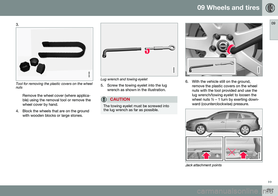
3.
Tool for removing the plastic covers on the wheel nuts
Remove the wheel cover (where applica- ble) using the removal tool or remove thewheel cover by hand.
4. Block the wheels that are on the ground with wooden blocks or large stones.Lug wrench and towing eyelet
5. Screw the towing eyelet into the lug wrench as shown in the illustration.
CAUTION
The towing eyelet must be screwed into the lug wrench as far as possible.
6. With the vehicle still on the ground,remove the plastic covers on the wheel nuts with the tool provided and use thelug wrench/towing eyelet to loosen thewheel nuts ½ – 1 turn by exerting down-ward (counterclockwise) pressure.
Jack attachment points
Page 300 of 402
||
09 Wheels and tires
09
298
7. There are two jack attachment points oneach side of the vehicle. Position the jack under the attachment point to be used ona level, firm, non-slippery surface andcrank it up until it is correctly aligned andseated in the attachment point. Beforeraising the vehicle, check that the jack isstill correctly positioned in the attach-ment.
8. Raise the vehicle until the wheel to be changed is lifted off the ground.
9. Unscrew the wheel nuts completely and remove the wheel.WARNING
•The jack must correctly engage the jack attachment.
• Be sure the jack is on a firm, level,non-slippery surface.
• Never allow any part of your body tobe extended under a vehicle suppor-ted by a jack.
• Use the jack intended for the vehiclewhen changing a tire. For any otherjob, use stands to support the vehicle.
• Apply the parking brake and put thegear selector in the Park (
P) position.
• Block the wheels standing on theground, use rigid wooden blocks orlarge stones.
• The jack should be kept well-greasedand clean, and should not be dam-aged.
• No objects should be placed betweenthe base of jack and the ground, orbetween the jack and the attachmentbar on the vehicle.
NOTE
The jack provided with your vehicle is intended to be used only in temporary sit-uations such as changing wheels in theevent of a flat tire. Only the jack that camewith your particular model should be usedto lift the vehicle. If the vehicle needs to belifted more frequently or for a prolongedperiod, using a garage jack or hoist is rec-ommended. Always follow this device’sinstructions for use.
Related information
•
Changing a wheel – installing a wheel (p. 300)
Page 302 of 402
09 Wheels and tires
09
300* Option/accessory, for more information, see Introduction.
Changing a wheel – accessing the spare wheel
The following procedure explains how to access the spare wheel (where applicable).
1. Release the bag's retaining straps.
2. Lift the bag out of the vehicle and remove
the spare wheel from the bag.
3. Fold up the floor hatch in the cargo area.
4. Remove the jack* and tools* from the foam block and change the wheels (see the instructions in the following section"Changing a wheel").
5. After changing wheels, return the jack and tools to the foam block and close thefloor hatch.
6. If possible, place the wheel with the punctured tire in the bag. 7. If there is a wheel in the bag, strap the
bag securely in place in the cargo area.WARNING
•If there is a wheel in the bag, the bag must be securely restrained using itsstraps and the load anchoring eyelets inthe cargo area. See (p. 299) and care-fully follow the instructions.
• If the wheel with the punctured tire istoo big to fit in the bag, it should besecurely restrained in the cargo areausing suitable straps, a net for anchor-ing cargo, etc.
Changing a wheel – installing a wheel
It is important to re-install wheels properly.
Re-installing the wheel1. Clean the contact surfaces on the wheel
and hub.
2. Lift the wheel and place it on the hub.
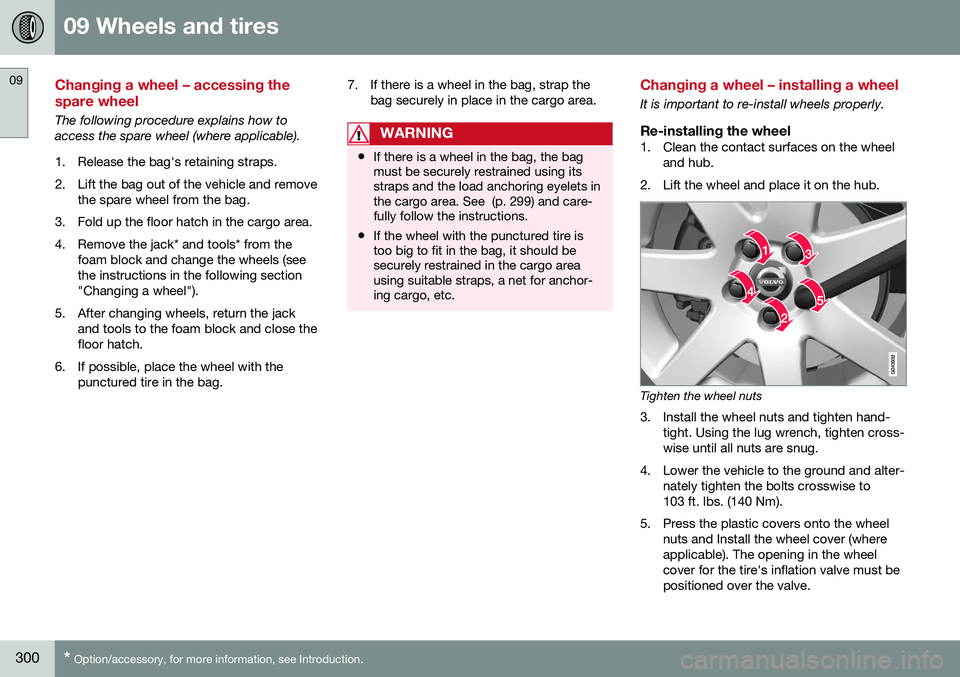
Tighten the wheel nuts
3. Install the wheel nuts and tighten hand- tight. Using the lug wrench, tighten cross- wise until all nuts are snug.
4. Lower the vehicle to the ground and alter- nately tighten the bolts crosswise to103 ft. lbs. (140 Nm).
5. Press the plastic covers onto the wheel nuts and Install the wheel cover (whereapplicable). The opening in the wheelcover for the tire's inflation valve must bepositioned over the valve.
Page 311 of 402
09 Wheels and tires
09
309
WARNING
The temperature grade for this tire is established for a tire that is properly infla-ted and not overloaded. Excessive speed,under-inflation, or excessive loading, eitherseparately or in combination, can causeheat buildup and tire failure.
Snow chains
Snow chains can be used on your Volvo with the following restrictions:
• Snow chains should be installed on front wheels only. Use only Volvo approvedsnow chains.
• If accessory, aftermarket or "custom"tires and wheels are installed and are of asize different than the original tires andwheels, chains in some cases CANNOTbe used. Sufficient clearances betweenchains and brakes, suspension and bodycomponents must be maintained.
• Some strap-on type chains will interferewith brake components and thereforeCANNOT be used.
• All Wheel Drive models
: Snow chains
should only be installed on the frontwheels.
• Certain size tires may not allow theassembly of snow chains/traction devi-ces.
Consult your Volvo retailer for additional snow chain information.CAUTION
• Check local regulations regarding the use of snow chains before installing.
• Use single-sided snow chains only.
• Always follow the chain manufactur-er's installation instructions carefully.Install chains as tightly as possible andretighten periodically.
• Never exceed the chain manufactur-er's specified maximum speed limit.(Under no circumstances should youexceed 31 mph (50 km/h).
• Avoid bumps, holes or sharp turnswhen driving with snow chains.
• The handling of the vehicle can beadversely affected when driving withchains. Avoid fast or sharp turns aswell as locked wheel braking.
Page 325 of 402

09 Wheels and tires
09
* Option/accessory, for more information, see Introduction.323
CAUTION
The compressor should not be used for more than 10 minutes at a time to avoidoverheating.
WARNING
If the pressure remains below 22 psi (1.8 bar) after approximately sevenminutes, turn off the compressor. In thiscase, the hole is too large to be sealed andthe vehicle should not be driven.
10. Switch off the compressor and discon-
nect the electrical wire from the 12-volt socket.
11. Unscrew the hose from the tire’s inflation valve and reinstall the valve cap.
CAUTION
•After inflating the tires, always reinstall the valve cap to help avoid damage tothe valve from dirt, gravel, etc.
• Use plastic valve caps only. Metal capscould corrode and become difficult toremove.
12. Immediately drive the vehicle for approxi-
mately 2 miles (3 km) at a maximum speed of 50 mph (80 km/h) to distributethe sealing compound in the tire.
CAUTION
If your vehicle is equipped with the Tire Pressure Monitoring System (TPMS), theuse of the sealing compound may lead toincorrect tire pressure readings or in rarecases, damage to the tire pressure sensor.Use the tire sealing system to check andadjust the damaged tire's inflation pres-sure.
NOTE
•Safely stow the tire sealing system in a convenient place as it will soon beused again to check the tire’s inflationpressure.
• The empty bottle of sealing compoundcannot be removed from the bottleholder. Consult a trained and qualifiedVolvo service technician to have thebottle removed and properly disposedof.
WARNING
If heavy vibrations, unsteady steering behavior, or noises should occur whiledriving, reduce speed and park the vehiclein a safe place. Recheck the tire forbumps, cracks, or other visible damage,and recheck its inflation pressure. If thepressure is below 19 psi (1.3 bar), do notcontinue driving. Have the vehicle towedto a trained and qualified Volvo servicetechnician.
Tire sealing system – checking inflation pressure
The tire sealing system can also be used to check the tires' inflation pressure.
Stage 2: Checking inflation pressure1. Connect the tire sealing system as
described in stage 1, see Tire sealing
system* – sealing hole (p. 321).
2. Refer to the inflation pressure table in this chapter for the correct inflation pressure.If the tire needs to be inflated, start thetire sealing system’s compressor. If nec-essary, release air from the tire by turningthe air release knob counterclockwise.
CAUTION
The compressor should not be used for more than 10 minutes at a time to avoidoverheating.
WARNING
If you interrupt your trip for more than 1 hour, check the inflation pressure in thedamaged tire again before continuing.
Page 326 of 402

09 Wheels and tires
09
324* Option/accessory, for more information, see Introduction.
Tire sealing system* – inflating tires
The tire sealing system can be used to inflate the tires. To do so:
1. Park the car in a safe place.
2. The compressor should be switched off.
Ensure that the on/off switch is in position0 (the 0 side of the switch should be
pressed down).
3. Take out the electrical wire and hose.
4. Remove the valve cap from the tire’s inflation valve and screw the hose con- nector onto the valve as tightly as possi-ble by hand.
5. Connect the electrical wire to the nearest 12-volt socket in the vehicle.
6. Start the vehicle’s engine.WARNING
• The vehicle’s engine should be running when the tire sealing system is used toavoid battery drain. Therefore, be surethe vehicle is parked in a well ventilatedplace, or outdoors, before using thesystem. The parking brake should besecurely applied and the gear selectorshould be in the
P (park) position.
• Children should never be left unatten-ded in the vehicle when the engine isrunning.
7. Check the tire’s inflation pressure on the
gauge. Switch off the compressor briefly to get a clear reading from the pressuregauge.
8. Refer to the tire inflation table in this chapter for the correct inflation pressure.If the tire needs to be inflated, start thetire sealing system’s compressor (pressthe on/off switch to position I). If neces-sary, release air from the tire by turningthe air release knob counterclockwise.
CAUTION
The compressor should not be used for more than 10 minutes at a time to avoidoverheating.
9. Turn off the compressor (press the on/off switch to position 0) when the correct
inflation pressure has been reached.
10. Unscrew the hose from the tire’s inflation valve and reinstall the valve cap.
CAUTION
•After inflating the tires, always reinstall the valve cap to help avoid damage tothe valve from dirt, gravel, etc.
• Use plastic valve caps only. Metal capscould corrode and become difficult toremove.
11. Disconnect the electrical wire from the
12-volt socket.
Page 334 of 402

||
10 Maintenance and servicing
10
332
where any retailer can access or search for this information using your vehicle's VIN num-ber. This number can be found in your war-ranty booklet or on the dashboard at thelower left corner of the windshield.
–Select Maintenance & repairSend
vehicle data.
Booking information and vehicle dataWhen you opt to book service from your vehi- cle, booking information and vehicle data willbe transmitted. Vehicle data consists of anumber of parameters in the following areas:
• Service requirements
• Function status
• Fluid levels
• Odometer reading (mileage)
• Vehicle Identification Number (VIN)
• The vehicle's software version
Related information
•Volvo ID (p. 21)
Maintenance – opening/closing hood
The hood is opened by first releasing the lock from the passenger compartment and thenpressing the release control.
Opening and closing the hood
Turn the handle located under the left side of the dash approximately 20-25degrees clockwise to release the hoodlock.
Lift the hood slightly. Press the release control (located under the right front edgeof the hood) to the left, and lift the hood.
WARNING
Check that the hood locks properly when closed.
Related information
•Maintenance – owner maintenance (p. 328)
• Engine compartment – overview (p. 333)
Page 342 of 402
||
10 Maintenance and servicing
10
340* Option/accessory, for more information, see Introduction.
CAUTION
Never touch the glass of bulbs with your fingers. Grease and oils from your fingersvaporize in the heat and will leave adeposit on the reflector, which will damageit.
WARNING
• The engine should not be running when changing bulbs.
• If the engine has been running justprior to replacing bulbs in the head-light housing, please keep in mind thatcomponents in the engine compart-ment will be hot.
WARNING
•
Active Bending Lights* – due to the high voltage used by these headlights,these bulbs should only be replacedby a trained and qualified Volvo serv-ice technician.
• Turn off the lights and remove theremote key from the ignition beforechanging any bulbs.
Related information
•
Bulbs – headlight housing (p. 340)
• Bulbs – taillight housing (p. 344)
• Bulbs – vanity mirror lighting (p. 346) •
Bulbs – cargo area lighting (p. 345)
• Bulbs – license plate lighting (p. 345)
Bulbs – headlight housing
The entire headlight housing must be lifted out when replacing all front bulbs.
Removing the headlight housing
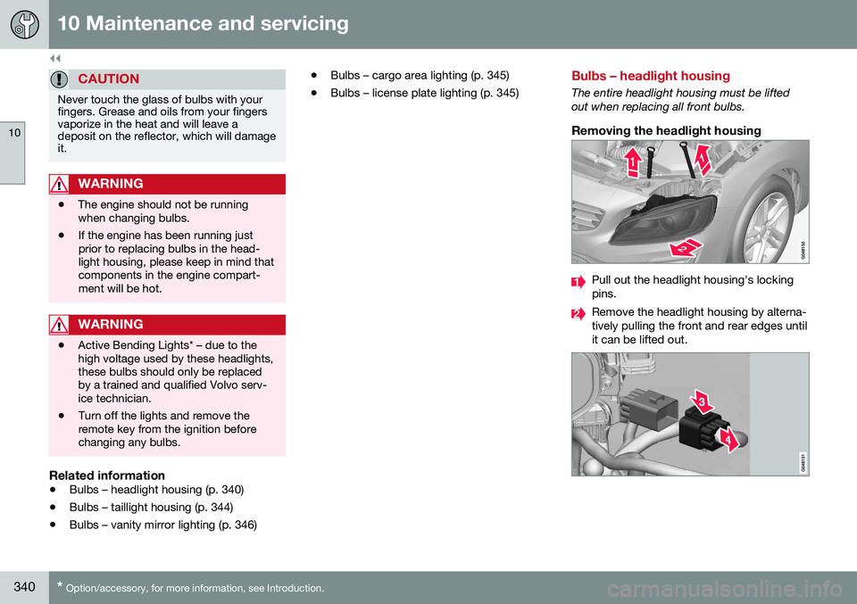
Pull out the headlight housing's locking pins.
Remove the headlight housing by alterna- tively pulling the front and rear edges untilit can be lifted out.