2016 VOLVO S80 trunk release
[x] Cancel search: trunk releasePage 82 of 380

03 Instruments and controls
03
80
Rear seats – folding backrest
The rear seat head restraints and backrests can be folded down. The center headrestraint can be raised/lowered according tothe passenger's height.
Folding down the rear seat backrests
The rear seat backrests are split and can be folded down together or separately1. Pull the release control handle(s).
2. Fold the backrest forward. Adjust the center seat head restraint if necessary.
NOTE
When the backrests are folded down, move the outboard head restraints forwardslightly so that they do not catch on theseat cushion.
CAUTION
To help avoid damage to the upholstery, there should be no objects on the rear seatand the seat belt should not be buckledwhen the backrest is folded down.
WARNING
•Keep vehicle doors and trunk locked and keep keys out of a child’s reach.Unsupervised children could lockthemselves in an open trunk and riskinjury. Children should be taught not toplay in vehicles.
• On hot days, the temperature in thetrunk or vehicle interior can rise veryquickly. Exposure of people to thesehigh temperatures for even a shortperiod of time can cause heat-relatedinjury or death. Small children are par-ticularly at risk.
WARNING
•
When one or more sections of the backrest is returned to the uprightposition, check that it is properlylocked in place by pushing and pullingit.
• Return the outboard head restraints tothe upright position.
• Long loads should always be securelyanchored to help avoid injury in theevent of a sudden stop.
• Always turn the engine off and applythe parking brake when loading/unloading the vehicle.
• Place the transmission in the Park (
P)
position to help prevent inadvertentmovement of the gear selector.
• On hot days, the temperature in thevehicle interior can rise very quickly.Exposure of people to these high tem-peratures for even a short period oftime can cause heat-related injury ordeath. Small children are particularly atrisk.
Related information
•
Front seats (p. 74)
• Front seats – power seat (p. 75)
• Rear seats – head restraints (p. 78)
Page 92 of 380

||
03 Instruments and controls
03
90
Related information
•Rear interior lighting (p. 90)
Rear interior lighting
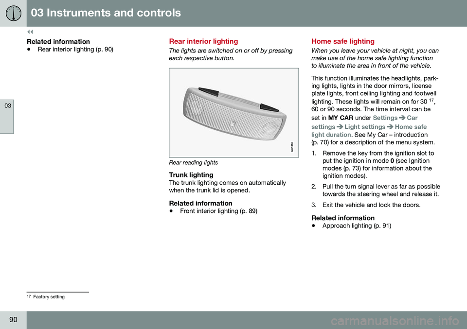
The lights are switched on or off by pressing each respective button.
G021150
Rear reading lights
Trunk lightingThe trunk lighting comes on automatically when the trunk lid is opened.
Related information
•Front interior lighting (p. 89)
Home safe lighting
When you leave your vehicle at night, you can make use of the home safe lighting functionto illuminate the area in front of the vehicle. This function illuminates the headlights, park- ing lights, lights in the door mirrors, licenseplate lights, front ceiling lighting and footwell lighting. These lights will remain on for 30 17
,
60 or 90 seconds. The time interval can be set in MY CAR under
SettingsCar
settings
Light settingsHome safe
light duration. See My Car – introduction
(p. 70) for a description of the menu system.
1. Remove the key from the ignition slot to put the ignition in mode 0 (see Ignition
modes (p. 73) for information about the ignition modes).
2. Pull the turn signal lever as far as possible towards the steering wheel and release it.
3. Exit the vehicle and lock the doors.
Related information
• Approach lighting (p. 91)
17
Factory setting
Page 159 of 380

06 Locks and alarm
06
}}
157
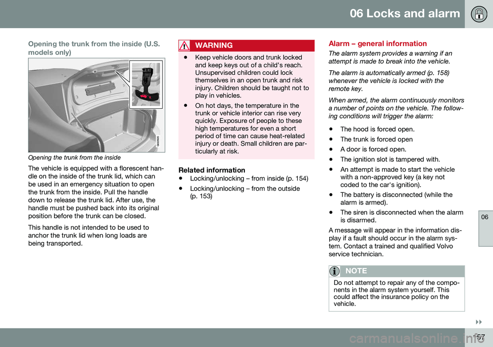
Opening the trunk from the inside (U.S. models only)
G022920
Opening the trunk from the insideThe vehicle is equipped with a florescent han- dle on the inside of the trunk lid, which canbe used in an emergency situation to openthe trunk from the inside. Pull the handledown to release the trunk lid. After use, thehandle must be pushed back into its originalposition before the trunk can be closed. This handle is not intended to be used to anchor the trunk lid when long loads arebeing transported.
WARNING
• Keep vehicle doors and trunk locked and keep keys out of a child’s reach.Unsupervised children could lockthemselves in an open trunk and riskinjury. Children should be taught not toplay in vehicles.
• On hot days, the temperature in thetrunk or vehicle interior can rise veryquickly. Exposure of people to thesehigh temperatures for even a shortperiod of time can cause heat-relatedinjury or death. Small children are par-ticularly at risk.
Related information
•
Locking/unlocking – from inside (p. 154)
• Locking/unlocking – from the outside (p. 153)
Alarm – general information
The alarm system provides a warning if an attempt is made to break into the vehicle. The alarm is automatically armed (p. 158) whenever the vehicle is locked with theremote key. When armed, the alarm continuously monitors a number of points on the vehicle. The follow-ing conditions will trigger the alarm:
• The hood is forced open.
• The trunk is forced open
• A door is forced open.
• The ignition slot is tampered with.
• An attempt is made to start the vehicle with a non-approved key (a key notcoded to the car's ignition).
• The battery is disconnected (while thealarm is armed).
• The siren is disconnected when the alarmis disarmed.
A message will appear in the information dis- play if a fault should occur in the alarm sys-tem. Contact a trained and qualified Volvoservice technician.
NOTE
Do not attempt to repair any of the compo- nents in the alarm system yourself. Thiscould affect the insurance policy on thevehicle.
Page 265 of 380

08 Starting and driving
08
}}
263
WARNING
Never carry a cell phone that is switched
on while refueling your vehicle. If the
phone rings, this may cause a spark that could ignite gasoline fumes, resulting infire and injury.
WARNING
Carbon monoxide is a poisonous, color- less, and odorless gas. It is present in allexhaust gases. If you ever smell exhaustfumes inside the vehicle, make sure thepassenger compartment is ventilated, andimmediately return the vehicle to a trainedand qualified Volvo service technician forcorrection.
Related information
• Refueling – fuel requirements (p. 261)
Refueling – opening/closing fuel filler door
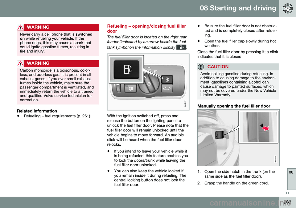
The fuel filler door is located on the right rear fender (indicated by an arrow beside the fuel tank symbol on the information display
)
With the ignition switched off, press and release the button on the lighting panel tounlock the fuel filler door. Please note that thefuel filler door will remain unlocked until thevehicle begins to move forward. An audibleclick will be heard when the fuel filler doorrelocks. •If you intend to leave your vehicle while it is being refueled, this feature enables youto lock the doors/trunk while leaving thefuel filler door unlocked.
• You can also keep the vehicle locked ifyou remain inside it during refueling. Thecentral locking button does not lock thefuel filler door. •
Be sure the fuel filler door is not obstruc-ted and is completely closed after refuel-ing.
• Open the fuel filler cap slowly during hotweather.
Close the fuel filler door by pressing it; a click indicates that it is closed.
CAUTION
Avoid spilling gasoline during refueling. In addition to causing damage to the environ-ment, gasolines containing alcohol cancause damage to painted surfaces, whichmay not be covered under the New VehicleLimited Warranty.
Manually opening the fuel filler door
G024631
1. Open the side hatch in the trunk (on the same side as the fuel filler door).
2. Grasp the handle on the green cord.
Page 328 of 380

10 Maintenance and servicing
10
326* Option/accessory, for more information, see Introduction.
Bulbs – trunk lighting
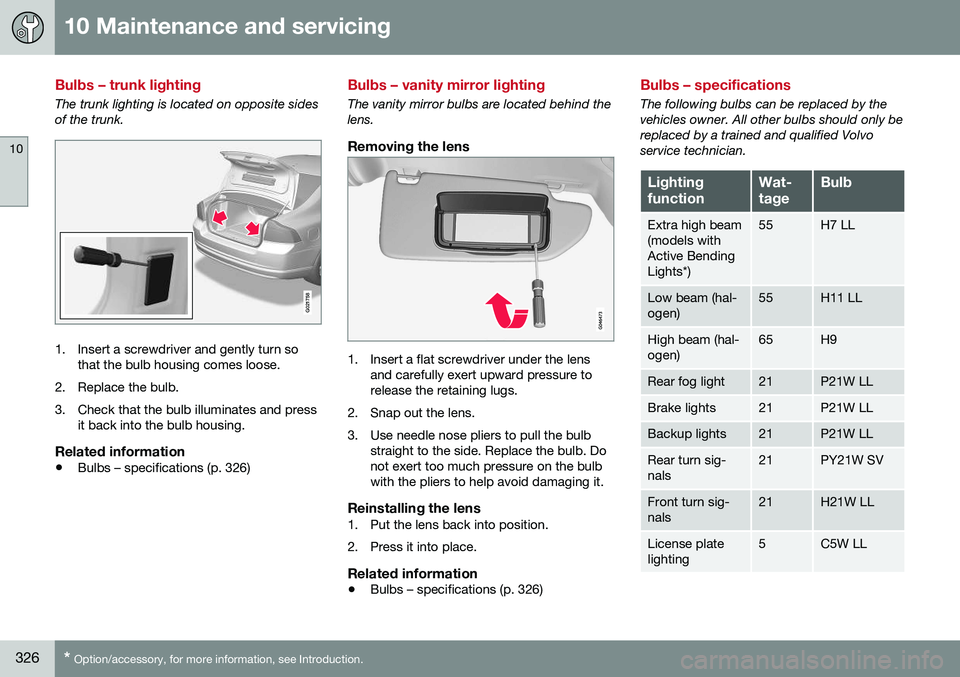
The trunk lighting is located on opposite sides of the trunk.
G021758
1. Insert a screwdriver and gently turn so
that the bulb housing comes loose.
2. Replace the bulb.
3. Check that the bulb illuminates and press it back into the bulb housing.
Related information
• Bulbs – specifications (p. 326)
Bulbs – vanity mirror lighting
The vanity mirror bulbs are located behind the lens.
Removing the lens
1. Insert a flat screwdriver under the lens
and carefully exert upward pressure to release the retaining lugs.
2. Snap out the lens.
3. Use needle nose pliers to pull the bulb straight to the side. Replace the bulb. Do not exert too much pressure on the bulbwith the pliers to help avoid damaging it.
Reinstalling the lens1. Put the lens back into position.
2. Press it into place.
Related information
• Bulbs – specifications (p. 326)
Bulbs – specifications
The following bulbs can be replaced by the vehicles owner. All other bulbs should only bereplaced by a trained and qualified Volvoservice technician.
Lighting functionWat- tageBulb
Extra high beam (models withActive BendingLights*)55H7 LL
Low beam (hal- ogen)55H11 LL
High beam (hal- ogen)65H9
Rear fog light21P21W LL
Brake lights21P21W LL
Backup lights21P21W LL
Rear turn sig- nals21PY21W SV
Front turn sig- nals21H21W LL
License plate lighting5C5W LL
Page 335 of 380

10 Maintenance and servicing
10
}}
333
RemovalSwitch off the ignition, remove the remote key from the ignition slot and wait at least5 minutes before disconnecting the battery sothat all information in the vehicle's electricalsystem can be stored in the control modules.
Open the clips on the front cover and remove the cover.
Release the rubber molding so that the rear cover is free.
Remove the rear cover by pulling it away.
Detach the black negative cable.
Detach the red positive cable
Detach the ventilation hose from the
battery
Loosen the screw holding the battery
clamp.
Move the battery to the side and lift it up.
WARNING
PROPOSITION 65 WARNING! Battery posts, terminals, and related accessories contain lead and lead com-pounds, chemicals known to the state ofCalifornia to cause cancer and reproduc-tive harm. Wash hands after handling.
Installation1. Lower the battery into the battery box.
2. Move the battery inward and to the side until it reaches the rear edge of the box.
3. Tighten the clamp that secures the bat- tery.
4. Connect the ventilation hose. > Be sure that it is correctly connectedto the battery and the vent in the vehi- cle's body.
5. Connect the red positive cable.
6. Connect the black negative cable.
7. Press in the rear cover. (See Removal).
8. Reinstall the molding. (See Removal).
9. Reinstall the front cover and secure it with the clips. (See Removal).
Related information
• Battery – handling (p. 330)
• Battery – symbols (p. 330)
Fuses – introduction
The fuses help protect the vehicle's electrical components from overloading. There are relay/fuseboxes located in the engine compartment, the passenger com-partment and the trunk. If an electrical component fails to function, this may be due to a blown fuse. The easiestway to see if a fuse is blown is to remove it. To do so:
1. Pull the fuse straight out. If a fuse is diffi-
cult to remove, a special fuse removal
tool is located on the inside of the engine compartment fusebox cover .
2. From the side, examine the curved metal wire in the fuse to see if it is intact.
If the wire is broken, insert a new fuse of the same color and amperage (written on thefuse). If fuses burn out repeatedly, have the electri- cal system inspected by a trained and quali-fied Volvo service technician.
WARNING
Never use metal objects or fuses with higher amperage than those stated on thefollowing pages. Doing so could seriouslydamage or overload the vehicle's electricalsystem.