2016 VOLVO S80 battery
[x] Cancel search: batteryPage 256 of 380

08 Starting and driving
08
254
Parking brake – general information
The electric parking brake helps to keep the vehicle stationary when it is parked.
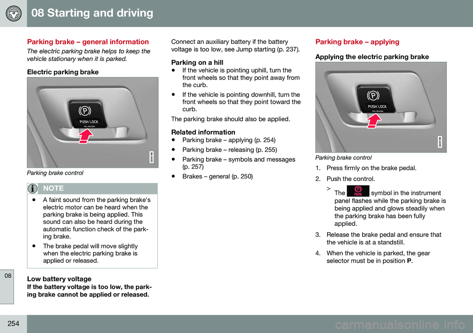
Electric parking brake
Parking brake control
NOTE
•A faint sound from the parking brake's electric motor can be heard when theparking brake is being applied. Thissound can also be heard during theautomatic function check of the park-ing brake.
• The brake pedal will move slightlywhen the electric parking brake isapplied or released.
Low battery voltageIf the battery voltage is too low, the park- ing brake cannot be applied or released. Connect an auxiliary battery if the batteryvoltage is too low, see Jump starting (p. 237).
Parking on a hill
•
If the vehicle is pointing uphill, turn the front wheels so that they point away fromthe curb.
• If the vehicle is pointing downhill, turn thefront wheels so that they point toward thecurb.
The parking brake should also be applied.
Related information
• Parking brake – applying (p. 254)
• Parking brake – releasing (p. 255)
• Parking brake – symbols and messages(p. 257)
• Brakes – general (p. 250)
Parking brake – applying
Applying the electric parking brake
Parking brake control
1. Press firmly on the brake pedal.
2. Push the control. >The
symbol in the instrument
panel flashes while the parking brake is being applied and glows steadily whenthe parking brake has been fullyapplied.
3. Release the brake pedal and ensure that the vehicle is at a standstill.
4. When the vehicle is parked, the gear selector must be in position P.
Page 261 of 380

08 Starting and driving
08
}}
259
Engine and cooling system
Under special conditions, for example when driving in hilly terrain, extreme heat or withheavy loads, there is a risk that the engine andcooling system will overheat. Proceed as follows to avoid overheating the engine. •Maintain a low speed when driving with a trailer up long, steep hills. For informa-tion, see Towing a trailer (p. 267)
• Do not turn the engine off immediatelywhen stopping after a hard drive.
WARNING
The cooling fan may start or continue to operate (for up to 6 minutes) after theengine has been switched off.
•
Remove any auxiliary lights from in front of the grille when driving in hot weatherconditions.
• Do not exceed engine speeds of4500 rpm if driving with a trailer in hillyterrain. The oil temperature could becometoo high.
Conserving electrical current
Keep the following in mind to help minimize battery drain:
• When the engine is not running, avoid using ignition mode
II. Many electrical
systems (the audio system, the optionalnavigation system, power windows, etc)will function in ignition modes 0 and I.
These modes reduce drain on the battery.
• Please keep in mind that using systems,accessories, etc., that consume a greatdeal of current when the engine is notrunning could result in the battery beingcompletely drained. Driving or having theengine running for approximately15 minutes will help keep the batterycharged.
• The optional 12-volt socket in thetrunk (p. 135) area provides electrical cur-rent even with the ignition switched off,which drains the battery.
Before a long distance trip
It is always worthwhile to have your vehicle checked by a trained and qualified Volvo serv-ice technician before driving long distances.Your retailer will also be able to supply youwith bulbs, fuses, spark plugs and wiperblades for your use in the event that problemsoccur. As a minimum, the following items should be checked before any long trip:
• Check that engine runs smoothly and that fuel consumption is normal.
• Check for fuel, oil, and fluid leakage.
• Have the transmission oil level (p. 362)checked.
• Check condition of drive belts.
• Check state of the battery's charge.
• Examine tires carefully (the spare tire aswell), and replace those that areworn (p. 275). Check tire pres-sure (p. 282).
• The brakes, front wheel alignment, andsteering gear should be checked by atrained and qualified Volvo service techni-cian only.
• Check all lights, including high beams.
• Reflective warning triangles are legallyrequired in some states/provinces.
• Have a word with a trained and qualifiedVolvo service technician if you intend to
Page 262 of 380

||
08 Starting and driving
08
260
drive in countries where it may be difficult to obtain the correct fuel.
• Consider your destination. If you will bedriving through an area where snow or iceare likely to occur, consider snowtires (p. 290).
Related information
•Changing a wheel – removing wheel(p. 276)
• Bulbs – introduction (p. 319)
Driving in cold weather
Check your vehicle before the approach of cold weather. The following advice is worth noting:
• Make sure that the engine cool- ant (p. 316) contains 50 percent anti-freeze. Any other mixture will reducefreeze protection. This gives protectionagainst freezing down to –31 °F (–35 °C).The use of "recycled" antifreeze is notapproved by Volvo. Different types ofantifreeze must not be mixed.
• Volvo recommends using only genuineVolvo antifreeze in your vehicle's radiator.
• Try to keep the fuel tank well filled – thishelps prevent the formation of condensa-tion in the tank. In addition, in extremelycold weather conditions it is worthwhileto add fuel line de-icer before refueling.
• The viscosity of the engine oil is impor-tant. Oil with low viscosity (thinner oil)improves cold-weather starting as well asdecreasing fuel consumption while theengine is warming up. Full synthetic0W-30 oil is recommended for driving inareas with sustained low temperatures.
• The load placed on the battery is greaterduring the winter since the windshieldwipers, lighting, etc., are used moreoften. Moreover, the capacity of the bat-tery decreases as the temperature drops.In very cold weather, a poorly chargedbattery can freeze and be damaged. It is therefore advisable to check the state ofcharge more frequently and spray an anti-rust oil on the battery posts.
• Volvo recommends the use of snow tireson all four wheels for winter driving, seeSnow tires/studded tires (p. 290).
• To prevent the washer fluid (p. 329)reser-voir from freezing, add washer solventscontaining antifreeze. This is importantsince dirt is often splashed on the wind-shield during winter driving, requiring thefrequent use of the washers and wipers.Volvo Washer Solvent should be dilutedas follows: Down to 14 °F (–10 °C): 1 partwasher solvent and 4 parts water Downto 5 °F (–15 °C): 1 part washer solventand 3 parts water Down to 0 °F (–18 °C):1 part washer solvent and 2 parts waterDown to –18 °F (–28 °C): 1 part washersolvent and 1 part water.
• Use Volvo Teflon Lock Spray in the locks.
• Avoid using de-icing sprays as they cancause damage to the locks.
Page 272 of 380

||
08 Starting and driving
08
270
CAUTION
General towing precautions:• Please check with state and local authorities before attempting this typeof towing, as vehicles being towed aresubject to regulations regarding maxi-mum towing speed, length and type oftowing device, lighting, etc.
• If the vehicle's battery is dead, seeJump starting (p. 237) to provide cur-rent for releasing the electric parkingbrake and to move the gear selectorfrom the
P position to N. If this is not
possible, see Transmission – shiftlockoverride (p. 242) for information aboutmanually overriding the shiftlock sys-tem to move the gear selector from P
to N.
• Maximum speed: 50 mph (80 km/h).Do not exceed the maximum allowabletowing speed.
• Maximum distance with front wheelson ground: 50 miles (80 km).
• The vehicle should only be towed inthe forward direction.
Related information
•
Towing eyelet (p. 270)
• Remote key – functions (p. 143)
Towing eyelet
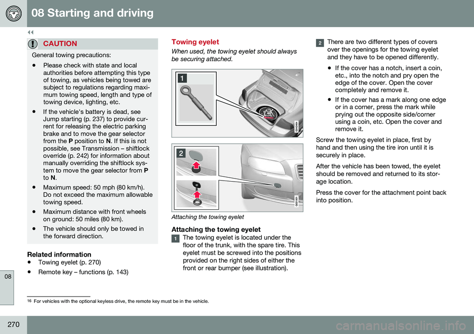
When used, the towing eyelet should always be securing attached.
Attaching the towing eyelet
Attaching the towing eyeletThe towing eyelet is located under the floor of the trunk, with the spare tire. Thiseyelet must be screwed into the positionsprovided on the right sides of either thefront or rear bumper (see illustration).
There are two different types of covers over the openings for the towing eyeletand they have to be opened differently.
• If the cover has a notch, insert a coin, etc., into the notch and pry open theedge of the cover. Open the covercompletely and remove it.
• If the cover has a mark along one edgeor in a corner, press the mark whileprying out the opposite side/cornerusing a coin, etc. Open the cover andremove it.
Screw the towing eyelet in place, first by hand and then using the tire iron until it issecurely in place. After the vehicle has been towed, the eyelet should be removed and returned to its stor-age location. Press the cover for the attachment point back into position.
16 For vehicles with the optional keyless drive, the remote key must be in the vehicle.
Page 304 of 380

||
09 Wheels and tires
09
302
WARNING
The bottle is equipped with a catch to keep it securely in place and help preventsealing compound leakage. Once in place,the bottle cannot be unscrewed. This mustbe done by a trained and qualified Volvoservice technician.
5. Remove the valve cap from the tire’sinflation valve and screw the tire sealing system’s hose connector onto the valveas tightly as possible by hand.
6. Connect the electrical wire to the nearest 12-volt socket in the vehicle.
NOTE
Be sure that none of the other 12-volt sockets is being used while the compres-sor is in operation.
7. Start the vehicle’s engine.
WARNING
The vehicle´s engine should be running when the tire sealing system is used toavoid battery drain. Therefore, be sure thevehicle is parked in a well ventilated place,or outdoors, before using the system.
8. Start the tire sealing system’s compres-sor by pressing the on/off switch to posi- tion I.
WARNING
• Never stand next to the tire being infla- ted when the compressor is in opera-tion.
• If cracks, bubbles, etc. form on the tire,switch off the compressor immediately.
• If there is visible damage to the sidewallor the rim, the tire cannot be repaired.The vehicle should not be driven if thisoccurs. Contact a towing service orVolvo On Call Roadside Assistance ifapplicable.
NOTE
The air pressure gauge will temporarily show an increase in pressure to approxi-mately 88 psi (6 bar) while the sealingcompound is being pumped into the tire.The pressure should return to a normallevel after approximately 30 seconds.
9. Within seven minutes, inflate the tire to
between 22—44 psi (1.8—3.0 bar). Switch off the compressor briefly to get aclear reading from the pressure gauge.
Page 306 of 380

09 Wheels and tires
09
304* Option/accessory, for more information, see Introduction.
Tire sealing system* – inflating tires
The tire sealing system can be used to inflate the tires. To do so:
1. Park the car in a safe place.
2. The compressor should be switched off.
Ensure that the on/off switch is in position0 (the 0 side of the switch should be
pressed down).
3. Take out the electrical wire and hose.
4. Remove the valve cap from the tire’s inflation valve and screw the hose con- nector onto the valve as tightly as possi-ble by hand.
5. Connect the electrical wire to the nearest 12-volt socket in the vehicle.
6. Start the vehicle’s engine.WARNING
• The vehicle’s engine should be running when the tire sealing system is used toavoid battery drain. Therefore, be surethe vehicle is parked in a well ventilatedplace, or outdoors, before using thesystem. The parking brake should besecurely applied and the gear selectorshould be in the
P (park) position.
• Children should never be left unatten-ded in the vehicle when the engine isrunning.
7. Check the tire’s inflation pressure on the
gauge. Switch off the compressor briefly to get a clear reading from the pressuregauge.
8. Refer to the tire inflation table in this chapter for the correct inflation pressure.If the tire needs to be inflated, start thetire sealing system’s compressor (pressthe on/off switch to position I). If neces-sary, release air from the tire by turningthe air release knob counterclockwise.
CAUTION
The compressor should not be used for more than 10 minutes at a time to avoidoverheating.
9. Turn off the compressor (press the on/off switch to position 0) when the correct
inflation pressure has been reached.
10. Unscrew the hose from the tire’s inflation valve and reinstall the valve cap.
CAUTION
•After inflating the tires, always reinstall the valve cap to help avoid damage tothe valve from dirt, gravel, etc.
• Use plastic valve caps only. Metal capscould corrode and become difficult toremove.
11. Disconnect the electrical wire from the
12-volt socket.
Page 310 of 380

10 Maintenance and servicing
10
308
Maintenance – owner maintenance
Periodic maintenance requirements and inter- vals are described in your vehicle's Warrantyand Service Records Information booklet. The following points can be carried out between the normally scheduled maintenanceservices.
Owner maintenance
Each time the car is refueled:
•Check the engine oil level.
• Clean the windshield, windshield wipers, headlights, and taillights.
Monthly:
• Check cold tire pressure in all tires. Inspect the tires for wear.
• Check that engine coolant and other fluidlevels are between the indicated "min"and "max" markings.
• Clean interior glass surfaces with a glasscleaner and soft paper towels.
• Wipe driver information displays with asoft cloth.
• Visually inspect battery terminals for cor-rosion. Corrosion may indicate a looseterminal connector, or a battery near theend of its useful service life. Consult yourVolvo retailer for additional information.
As needed:Wash the car, including the undercarriage, to reduce wear that can be caused by a buildup of dirt, and corrosion that can be caused bysalt residues. Clean leaves and twigs from air intake vents at the base of the windshield, and from otherplaces where they may collect.
NOTE
Complete service information for qualified technicians is available online for purchaseor subscription at www.volvotechinfo.com.
Related information
•
Maintenance – opening/closing hood (p. 312)
• Engine compartment – overview (p. 313)
• Engine compartment – coolant (p. 316)
• Engine compartment – engine oil (p. 314)
• Engine compartment – power steeringfluid (p. 318)
• Engine compartment – washer fluid(p. 329)
• Cleaning the interior (p. 347)
• Washing the car (p. 345)
• Tire inflation – checking pressure (p. 282)
• Tires – tread wear indicator (p. 275)
Page 312 of 380

10 Maintenance and servicing
10
310* Option/accessory, for more information, see Introduction.
Onboard Diagnostic System
OBD II is part of your vehicle's computerized engine management system. It stores diag-nostic information about your vehicle's emis-sion controls. It can light the Check Enginelight (MIL) if it detects an emission control"fault." A "fault" is a component or systemthat is not performing within an expectedrange. A fault may be permanent or tempo-rary. OBD II will store a message about anyfault.
Emission inspection readiness
How do states use OBD II for emission inspections?
Many states connect a computer directly to a vehicle's OBD II system. The inspector canthen read "faults." In some states, this type ofinspection has replaced the tailpipe emissiontest.
How can my vehicle fail OBD II emission
inspection?
Your vehicle can fail OBD II emission inspec- tion for any of the following reasons.
• If your Check Engine (MIL) light is lit, your vehicle may fail inspection.
• If your vehicle's Check Engine light waslit, but went out without any action onyour part, OBD II will still have a recordedfault. Your vehicle may pass or fail,depending on the inspection practices inyour area. •
If you had recent service that requireddisconnecting the battery, OBD II diag-nostic information may be incompleteand "not ready" for inspection. A vehiclethat is not ready may fail inspection.
How can I prepare for my next OBD II
emission inspection?
• If your Check Engine (MIL) light is lit – or was lit but went out without service, haveyour vehicle diagnosed and, if necessary,serviced by a qualified Volvo technician.
• If you recently had service for a lit CheckEngine light, or if you had service thatrequired disconnecting the battery, aperiod of driving is necessary to bring theOBD II system to "ready" for inspection.Two half-hour trips of mixed stop-and-go/highway driving are typically neededto allow OBD II to reach readiness. YourVolvo retailer can provide you with moreinformation on planning a trip.
• Maintain your vehicle in accordance withyour vehicle's maintenance schedule.
Booking service and repairs
Connected Service Booking (CSB) makes set- ting up a time for service, maintenance and/orrepairs directly from the vehicle quick andconvenient.
Prerequisites
• The owner (primary driver) must have a valid Volvo ID. See Volvo ID (p. 21) foradditional information.
• The vehicle must be connected to the Internet using a paired Bluetooth ®
cell
phone. See your Sensus Infotainment supplement for information on pairing acell phone. On models equipped withVolvo On Call (VOC)*, you can connect tothe Internet using your separate VOCdata plan. Refer to your separate VolvoOn Call manual.
• By default, the retailer where you pur-chased your vehicle will be your preferred(primary) retailer/Volvo authorized work-shop who will perform service and repairson your vehicle. To change the preferredretailer, go to Dealer Locator atvolvocars.com and select a retailer, clickon Service Scheduler and book anappointment at the new preferred retailer.
• In order to be guided through the on-screen steps, the menu alternative
Display notifications must be activated.
CSB menu accessOnce the prerequisites have been estab- lished, all CSB-related menus can be