2016 VOLVO S80 run flat
[x] Cancel search: run flatPage 285 of 380

09 Wheels and tires
09
}}
283
Tire specifications
The following information can be found on a tire's sidewall.
Tire ratings
Speed ratingsThe speed ratings in the table translate as fol- low:
Speed ratings
M81 mph (130 km/h)
Q100 mph (160 km/h)
T118 mph (190 km/h)
H130 mph (210 km/h)
V149 mph (240 km/h)
W168 mph (270 km/h)
Y186 mph (300 km/h)
Information on the sidewall
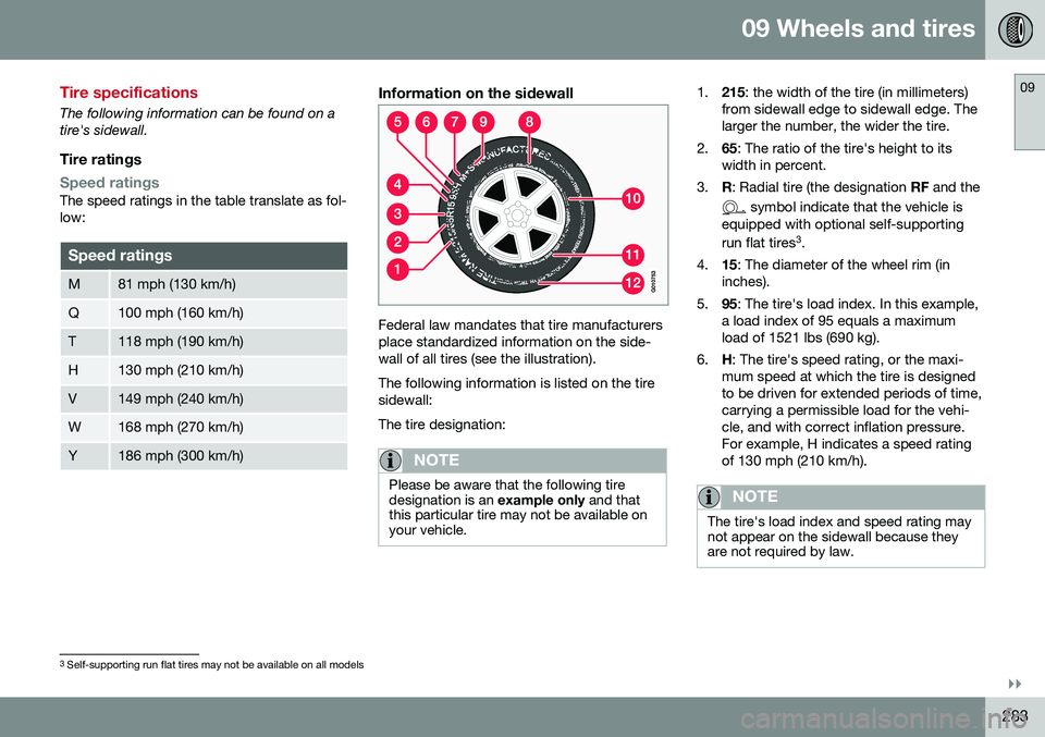
Federal law mandates that tire manufacturers place standardized information on the side-wall of all tires (see the illustration). The following information is listed on the tire sidewall: The tire designation:
NOTE
Please be aware that the following tire designation is an example only and that
this particular tire may not be available onyour vehicle.
1. 215: the width of the tire (in millimeters)
from sidewall edge to sidewall edge. The larger the number, the wider the tire.
2. 65: The ratio of the tire's height to its
width in percent.
3. R: Radial tire (the designation RF and the
symbol indicate that the vehicle is
equipped with optional self-supporting run flat tires 3
.
4. 15: The diameter of the wheel rim (in
inches).
5. 95: The tire's load index. In this example,
a load index of 95 equals a maximum load of 1521 lbs (690 kg).
6. H: The tire's speed rating, or the maxi-
mum speed at which the tire is designedto be driven for extended periods of time,carrying a permissible load for the vehi-cle, and with correct inflation pressure.For example, H indicates a speed ratingof 130 mph (210 km/h).
NOTE
The tire's load index and speed rating may not appear on the sidewall because theyare not required by law.
3 Self-supporting run flat tires may not be available on all models
Page 292 of 380

09 Wheels and tires
09
290
Snow tires/studded tires4
Owners who live in or regularly commute through areas with sustained periods of snowor icy driving conditions are strongly advisedto fit suitable winter tires to help retain thehighest degree of traction.
Tires for winter use:
•
It is important to install winter tires on all four wheels to help retain traction duringcornering, braking, and accelerating. Fail-ure to do so could reduce traction to anunsafe level or adversely affect handling.
• Do not mix tires of different design as thiscould also negatively affect overall tireroad grip.
• Winter tires wear more quickly on dryroads in warm weather. They should beremoved when the winter driving seasonhas ended.
• Studded tires should be run-in 300 – 600 miles (500 – 1000 km) during whichthe vehicle should be driven as smoothlyas possible to give the studs the opportu-nity to seat properly in the tires. The tiresshould have the same rotational directionthroughout their entire lifetime.
NOTE
Please consult state or provincial regula- tions restricting the use of studded wintertires before installing such tires.
Tire pressure monitoring - introduction
Volvo provides two different systems to moni- tor tire pressure: Tire Pressure MonitoringSystem (TPMS) or Tire Monitor.
Determining which tire monitoring system is in your vehicle
To see which system is installed in your vehi- cle, press the
MY CAR button on the center
console. Go to
SettingsCar settings.
• If your vehicle has a menu called
Tire
monitoring, see Tire Monitor - introduc-
tion (p. 295).
• If your vehicle has a menu called
Tire
pressure, see Tire Pressure Monitoring
System (TPMS) – general information (p. 291).
IntroductionEach tire, including the spare (if provided), should be checked monthly when cold andinflated to the inflation pressure recom-mended by the vehicle manufacturer on thevehicle placard or tire inflation pressure label.(If your vehicle has tires of a different sizethan the size indicated on the vehicle placardor tire inflation pressure label, you shoulddetermine the proper tire inflation pressure forthose tires.) As an added safety feature, your vehicle hasbeen equipped with a tire pressure monitor-ing system that illuminates a low tire pressure telltale (
) when one or more of your tires
is significantly under-inflated. Accordingly, when the low tire pressure telltale illuminates,you should stop and check your tires as soonas possible, and inflate them to the properpressure. Driving on a significantly under-inflated tire causes the tire to overheat and can lead totire failure. Under-inflation also reduces fuelefficiency and tire tread life, and may affectthe vehicle's handling and stopping ability.Please note that a tire pressure monitoringsystem is not a substitute for proper tiremaintenance, and it is the driver's responsi-bility to maintain correct tire pressure, even ifunder-inflation has not reached the level totrigger illumination of the system's low tirepressure telltale. Your vehicle has also been equipped with a TPMS malfunction indicator to indicate whenthe system is not operating properly. Themonitoring system's malfunction indicator iscombined with the low tire pressure telltale. When the system detects a malfunction, the telltale will flash for approximately one minuteand then remain continuously illuminated.This sequence will continue upon subsequentvehicle start-ups as long as the malfunction
4 Where permitted
Page 300 of 380

09 Wheels and tires
09
298* Option/accessory, for more information, see Introduction.
Self-supporting run flat tires (SST)
Self-supporting run flat tires are available as optional equipment on certain models. The vehicle must be equipped with one of the tire pressure monitoring systems if tires ofthis type are installed. Tires of this type have specially reinforced sidewalls that make it possible to continuedriving to a limited extent even though the tirehas lost some or all of its inflation pressure.These tires are mounted on special rims (nor-mal tires can also be mounted on these rims). If an SST tire loses inflation pressure, the yel- low TPMS symbol illuminates in the instru-ment panel and a text message is also dis-played. If this happens, reduce speed to notmore than 50 mph (80 km/h). The tire shouldbe replaced as soon as possible.WARNING
• SST tires should only be mounted by service technicians who are familiarwith tires of this type.
• SST tires may only be mounted onvehicles equipped with a tire pressuremonitoring system.
• Do not drive faster than 50 mph(80 km/h) if the monitoring system indi-cates that a tire has lost inflation pres-sure.
• Do not drive farther than 50 miles(80 km) before replacing a damagedSST tire.
• Drive carefully and avoid e.g., hardbraking or fast turns.
• SST tires must be replaced if they aredamaged. A tire of this type cannot berepaired.
Related information
•
Tire pressure monitoring - introduction (p. 290)
Tire sealing system* – general information
Certain models are equipped with a tire sealing system
* that enables you to tempo-
rarily seal a hole in the tread surface and re-inflate a flat tire, or to adjust a tire’s inflationpressure.
IntroductionThe tire sealing system consists of an air compressor, a container for the sealing com-pound, wiring to connect the system to thevehicle’s electrical system via one of the 12-volt sockets, and a hose used to connect thesystem to the tire’s inflation valve.
NOTE
The tire sealing system's compressor has been tested and approved by Volvo.
Page 301 of 380

09 Wheels and tires
09
}}
299
The 12-volt sockets are located in the front tunnel console and on the rear side of thecenter console in the rear seat.
Accessing the tire sealing systemThe tire sealing system is stowed under thefloor of the trunk. To access it:
1. Lift the floor hatch in the cargo area.
2. Lift out the tire sealing system.
NOTE
•
The tire sealing system is only intended to seal holes on the tire’stread area, not the sidewall.
• Tires with large holes or tears cannotbe repaired with the tire sealing sys-tem.
• After use, stow the tire sealing systemproperly to help prevent rattling.
WARNING
•After using the tire sealing system, the vehicle should not be driven fartherthan approximately 120 miles (200km).
• Have the tire inspected by a trainedand qualified Volvo service technicianas soon as possible to determine if itcan be permanently repaired or mustbe replaced.
• The vehicle should not be driven fasterthan 50 mph (80 km/h) while using atire that has been temporarily repairedwith the tire sealing system.
• After using the tire sealing system,drive carefully and avoid abrupt steer-ing maneuvers and sudden stops.
Tire sealing system–temporarily repairing a flat tire
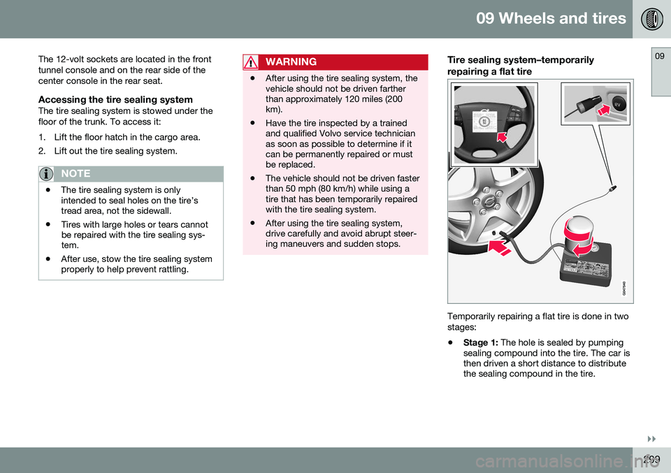
Temporarily repairing a flat tire is done in two stages:
• Stage 1:
The hole is sealed by pumping
sealing compound into the tire. The car is then driven a short distance to distributethe sealing compound in the tire.
Page 304 of 380

||
09 Wheels and tires
09
302
WARNING
The bottle is equipped with a catch to keep it securely in place and help preventsealing compound leakage. Once in place,the bottle cannot be unscrewed. This mustbe done by a trained and qualified Volvoservice technician.
5. Remove the valve cap from the tire’sinflation valve and screw the tire sealing system’s hose connector onto the valveas tightly as possible by hand.
6. Connect the electrical wire to the nearest 12-volt socket in the vehicle.
NOTE
Be sure that none of the other 12-volt sockets is being used while the compres-sor is in operation.
7. Start the vehicle’s engine.
WARNING
The vehicle´s engine should be running when the tire sealing system is used toavoid battery drain. Therefore, be sure thevehicle is parked in a well ventilated place,or outdoors, before using the system.
8. Start the tire sealing system’s compres-sor by pressing the on/off switch to posi- tion I.
WARNING
• Never stand next to the tire being infla- ted when the compressor is in opera-tion.
• If cracks, bubbles, etc. form on the tire,switch off the compressor immediately.
• If there is visible damage to the sidewallor the rim, the tire cannot be repaired.The vehicle should not be driven if thisoccurs. Contact a towing service orVolvo On Call Roadside Assistance ifapplicable.
NOTE
The air pressure gauge will temporarily show an increase in pressure to approxi-mately 88 psi (6 bar) while the sealingcompound is being pumped into the tire.The pressure should return to a normallevel after approximately 30 seconds.
9. Within seven minutes, inflate the tire to
between 22—44 psi (1.8—3.0 bar). Switch off the compressor briefly to get aclear reading from the pressure gauge.
Page 306 of 380

09 Wheels and tires
09
304* Option/accessory, for more information, see Introduction.
Tire sealing system* – inflating tires
The tire sealing system can be used to inflate the tires. To do so:
1. Park the car in a safe place.
2. The compressor should be switched off.
Ensure that the on/off switch is in position0 (the 0 side of the switch should be
pressed down).
3. Take out the electrical wire and hose.
4. Remove the valve cap from the tire’s inflation valve and screw the hose con- nector onto the valve as tightly as possi-ble by hand.
5. Connect the electrical wire to the nearest 12-volt socket in the vehicle.
6. Start the vehicle’s engine.WARNING
• The vehicle’s engine should be running when the tire sealing system is used toavoid battery drain. Therefore, be surethe vehicle is parked in a well ventilatedplace, or outdoors, before using thesystem. The parking brake should besecurely applied and the gear selectorshould be in the
P (park) position.
• Children should never be left unatten-ded in the vehicle when the engine isrunning.
7. Check the tire’s inflation pressure on the
gauge. Switch off the compressor briefly to get a clear reading from the pressuregauge.
8. Refer to the tire inflation table in this chapter for the correct inflation pressure.If the tire needs to be inflated, start thetire sealing system’s compressor (pressthe on/off switch to position I). If neces-sary, release air from the tire by turningthe air release knob counterclockwise.
CAUTION
The compressor should not be used for more than 10 minutes at a time to avoidoverheating.
9. Turn off the compressor (press the on/off switch to position 0) when the correct
inflation pressure has been reached.
10. Unscrew the hose from the tire’s inflation valve and reinstall the valve cap.
CAUTION
•After inflating the tires, always reinstall the valve cap to help avoid damage tothe valve from dirt, gravel, etc.
• Use plastic valve caps only. Metal capscould corrode and become difficult toremove.
11. Disconnect the electrical wire from the
12-volt socket.
Page 328 of 380

10 Maintenance and servicing
10
326* Option/accessory, for more information, see Introduction.
Bulbs – trunk lighting
The trunk lighting is located on opposite sides of the trunk.
G021758
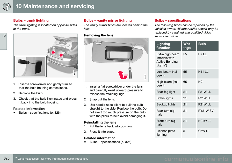
1. Insert a screwdriver and gently turn so
that the bulb housing comes loose.
2. Replace the bulb.
3. Check that the bulb illuminates and press it back into the bulb housing.
Related information
• Bulbs – specifications (p. 326)
Bulbs – vanity mirror lighting
The vanity mirror bulbs are located behind the lens.
Removing the lens
1. Insert a flat screwdriver under the lens
and carefully exert upward pressure to release the retaining lugs.
2. Snap out the lens.
3. Use needle nose pliers to pull the bulb straight to the side. Replace the bulb. Do not exert too much pressure on the bulbwith the pliers to help avoid damaging it.
Reinstalling the lens1. Put the lens back into position.
2. Press it into place.
Related information
• Bulbs – specifications (p. 326)
Bulbs – specifications
The following bulbs can be replaced by the vehicles owner. All other bulbs should only bereplaced by a trained and qualified Volvoservice technician.
Lighting functionWat- tageBulb
Extra high beam (models withActive BendingLights*)55H7 LL
Low beam (hal- ogen)55H11 LL
High beam (hal- ogen)65H9
Rear fog light21P21W LL
Brake lights21P21W LL
Backup lights21P21W LL
Rear turn sig- nals21PY21W SV
Front turn sig- nals21H21W LL
License plate lighting5C5W LL
Page 370 of 380

12 Index
12
368
A
ABS (anti-lock brake system).................. 252
Accessory installation warning.................. 23
Active chassis system............................. 162
Active high beams..................................... 84Active yaw control........................... 162, 163
Adaptive brake lights............................... 253
Adaptive cruise control.................... 171, 172Airbags disconnecting the front passenger’s
side....................................................... 36
front...................................................... 32
inflatable curtain................................... 41
side impact........................................... 39
Air conditioning........................................ 125
Air distribution.................................. 121, 127
Air distribution table................................. 129
Air vents................................................... 121
Alarm................................ 157, 158, 159, 160
All Wheel Drive......................................... 250
Ambient temperature sensor..................... 71
Anti-freeze....................................... 260, 316Anti-lock brake system warning light......................................... 67
Anti-lock Brake System (ABS)................. 252 Approach lighting.............................. 91, 143
Auto-dim rearview mirror........................... 98
Automatic locking retractor....................... 47Automatic transmission
Eco (driving function).......................... 248
Geartronic........................................... 240
general description..................... 238, 240
oil........................................................ 361
shiftlock override................................ 242
Axle weight.............................................. 286
B
Battery maintenance............................... 331, 332
remote key, replacing......................... 148
replacing............................................. 332
specifications...................................... 363
start/stop............................................ 363
warning symbols................................. 330
Blind Spot Information System (BLIS)..... 227
Booster cushions....................................... 53
Brake lights.............................................. 253Brake system ABS..................................................... 252
Brake pad inspection.......................... 251
checking fluid level............................. 317 emergency brake assistance.............. 253
fluid..................................................... 361
general information............................. 250
Bulbs headlights... 319, 320, 321, 322, 323, 324
introduction......................................... 319
license plate lights.............................. 325
side marker lights............................... 324
specifications...................................... 326
trunk lighting....................................... 326
C
Camera, Park Assist................................ 223
Capacity weight....................................... 286
Catalytic converter................................... 265
Central locking system, introduction 140, 141, 144, 147
Chains...................................................... 289
Check Engine warning light....................... 67Child restraints recalls and registration......................... 47
Child restraint systems.............................. 47 booster cushions.................................. 53
convertible seats.................................. 51
infant seats........................................... 49