2016 VAUXHALL MOVANO_B jump start
[x] Cancel search: jump startPage 124 of 233

122Driving and operatingfirst gear. On an uphill slope,
turn the front wheels away from
the kerb.
If the vehicle is on a downhill
slope, engage reverse gear.
Turn the front wheels towards
the kerb.
● Close the windows.
● Turn the ignition key to position
0 and remove it. Turn the
steering wheel until the
steering wheel lock is felt to
engage.
Lock the vehicle 3 21 and activate the
anti-theft locking system 3 30 and
anti-theft alarm system 3 31.
Air suspension
Operates automatically when the
vehicle is driven. The air suspension
system constantly adjusts the ride
height according to the vehicle load.
Caution
To ensure safe operation of the air
suspension system, do not exceed the maximum permissible gross
vehicle weight rating. Refer to
identification plate 3 199 or the
vehicle documents.
For further information on the air
suspension system, refer to the
operating instructions supplied.
Master switch
Caution
The air suspension system must
be switched off when the vehicle is being towed, jump‐started, raised
off the ground or transported.
Do not switch off the air
suspension system when driving.
Jump starting 3 188, Towing the
vehicle 3 190.
The master switch is located on the
door pillar.
Switch on to enable operation and
adjustment of the air suspension
system.
Page 136 of 233

134Driving and operatingInterruption of power supplyThe clutch is not disengaged if there
is an interruption of the power supply
when a gear is engaged. The vehicle
cannot move.
If the vehicle battery is discharged,
start the vehicle using jump leads
3 188.
If the cause of the fault is not a
discharged vehicle battery, seek the
assistance of a workshop.
If neutral cannot be selected, the
vehicle must only be towed with the
drive wheels raised off the ground
3 190.
Towing the vehicle 3 190.Brakes
The brake system comprises two
independent brake circuits.
If a brake circuit fails, the vehicle can
still be braked using the other brake
circuit. However, braking effect is
achieved only when you depress the
brake pedal firmly. You need to use
considerably more force for this. The
braking distance is extended. Seek
the assistance of a workshop before
continuing your journey.
When the engine is not running, the
support of the brake servo unit
disappears once the brake pedal has
been depressed once or twice.
Braking effect is not reduced, but
braking requires significantly greater
force. It is especially important to bear this in mind when being towed.
Control indicator R 3 85.
Antilock brake system
Antilock brake system (ABS)
prevents the wheels from locking.ABS starts to regulate brake pressure as soon as a wheel shows a tendency to lock. The vehicle remains
steerable, even during hard braking.
ABS control is made apparent
through a pulse in the brake pedal
and the noise of the regulation
process.
For optimum braking, keep the brake
pedal fully depressed throughout the
braking process, despite the fact that
the pedal is pulsating. Do not reduce
the pressure on the pedal.
Control indicator u 3 86.
Fault
If control indicators u and A
illuminate with the messages CHECK
ABS and CHECK ESP in the Driver
Information Centre (DIC), there is a fault in the ABS. The brake system
remains operational but without ABS
regulation.
Page 155 of 233

Vehicle care153Vehicle careGeneral Information...................154
Accessories and vehicle modifications .......................... 154
Vehicle storage ........................154
End-of-life vehicle recovery .....155
Vehicle checks ........................... 155
Performing work ......................155
Bonnet ..................................... 155
Engine oil ................................. 156
Engine coolant ......................... 157
Power steering fluid .................158
Washer fluid ............................ 159
Brakes ..................................... 159
Brake fluid ............................... 159
Vehicle battery ......................... 159
Diesel fuel filter ........................161
Diesel fuel system bleeding .....161
Wiper blade replacement ........162
Bulb replacement .......................162
Headlights ............................... 162
Adaptive forward lighting .........164
Fog lights ................................. 165
Front turn signal lights .............165
Tail lights ................................. 166
Side turn signal lights ..............167Centre high-mounted brake
light ......................................... 167
Number plate light ...................168
Interior lights ............................ 168
Instrument panel illumination ...169
Electrical system ........................170
Fuses ....................................... 170
Engine compartment fuse box . 171
Instrument panel fuse box .......171
Load compartment fuse box ....172
Vehicle tools .............................. 174
Tools ........................................ 174
Wheels and tyres .......................175
Tyres ....................................... 175
Winter tyres ............................. 176
Tyre designations ....................176
Tyre pressure .......................... 176
Tyre pressure monitoring system .................................... 177
Tread depth ............................. 179
Changing tyre and wheel size . 179 Wheel covers ........................... 180
Tyre chains .............................. 180
Tyre repair kit .......................... 180
Wheel changing .......................184
Spare wheel ............................ 185
Jump starting ............................. 188Towing....................................... 190
Towing the vehicle ...................190
Towing another vehicle ...........191
Appearance care .......................192
Exterior care ............................ 192
Interior care ............................. 193
Page 162 of 233
160Vehicle carebattery. Short-distance-driving and
frequent engine starts can discharge
the battery. Avoid the use of
unnecessary electrical consumers.
Batteries do not belong in household
waste. They must be disposed of at
an appropriate recycling collection
point.
Laying up the vehicle for more than
4 weeks can lead to battery
discharge. Disconnect the clamp from the negative terminal of the vehicle
battery.
Ensure the ignition is switched off
before connecting or disconnecting
the vehicle battery.
The anti-theft alarm siren must be
deactivated as follows: Switch the ignition on then off, disconnect the
vehicle's battery within 15 seconds.
Battery access
The battery is located behind a panel in the front left-hand door step.
Remove the panel to access the
battery.
Charging the vehicle battery
9 Danger
Ensure adequate ventilation when
charging the battery. There is a
risk of explosion if gases
generated during charging are
allowed to accumulate!
Jump starting 3 188.
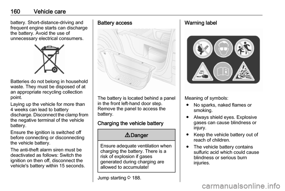
Warning label
Meaning of symbols:
● No sparks, naked flames or smoking.
● Always shield eyes. Explosive gases can cause blindness or
injury.
● Keep the vehicle battery out of reach of children.
● The vehicle battery contains sulfuric acid which could cause
blindness or serious burn
injuries.
Page 184 of 233
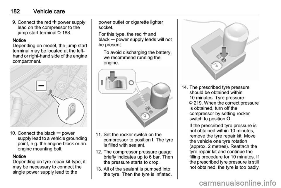
182Vehicle care9.Connect the red < power supply
lead on the compressor to the
jump start terminal 3 188.
Notice
Depending on model, the jump start
terminal may be located at the left-
hand or right-hand side of the engine compartment.
10. Connect the black ] power
supply lead to a vehicle grounding
point, e.g. the engine block or an
engine mounting bolt.
Notice
Depending on tyre repair kit type, it
may be necessary to connect the
single power supply lead to the
power outlet or cigarette lighter
socket.
For this type, the red < and
black ] power supply leads will not
be present.
To avoid discharging the battery,
we recommend running the
engine.
11. Set the rocker switch on the compressor to position I. The tyre
is filled with sealant.
12. The compressor pressure gauge briefly indicates up to 6 bar. Then
the pressure starts to drop.
13. All of the sealant is pumped into the tyre. Then the tyre is inflated.
14. The prescribed tyre pressureshould be obtained within
10 minutes. Tyre pressure
3 219 . When the correct pressure
is obtained, turn off the
compressor by setting rocker
switch to position O.
If the prescribed tyre pressure is
not obtained within 10 minutes,
remove the tyre repair kit. Move
the vehicle one tyre rotation
(approx. 2 metres). Reattach the
tyre repair kit and continue the
filling procedure for 10 minutes. If
the prescribed tyre pressure is still not obtained, the tyre is too badly
Page 190 of 233
188Vehicle careThe following applies to tyres fitted
opposing the rolling direction:
● Driveability may be affected. Have the defective tyre renewed
or repaired as soon as possible.
● Do not drive faster than 50 mph.
● Drive particularly carefully on wet
and snow-covered road
surfaces.Jump starting
Do not start with a quick charger.
A vehicle with a discharged battery
can be started using jump leads and
the battery of another vehicle.9 Warning
Be extremely careful when starting
with jump leads. Any deviation
from the following instructions can
lead to injuries or damage caused
by battery explosion or damage to the electrical systems of both
vehicles.
9 Warning
Avoid contact with eyes, skin,
fabrics, and painted surfaces. The fluid contains sulphuric acid which can cause injuries and damage in
the event of direct contact.
Caution
The air suspension system must
be switched off prior to jump
starting.
9 Warning
Avoid contact of the battery with
eyes, skin, fabrics and painted
surfaces. The fluid contains
sulphuric acid which can cause
injuries and damage in the event
of direct contact.
● Never expose the vehicle battery
to naked flames or sparks.
● A discharged vehicle battery can already freeze at a temperature
of 0 °C. Defrost the frozen vehicle
battery before connecting jump leads.
● Wear eye protection and protective clothing when
handling a vehicle battery.
Page 191 of 233
Vehicle care189● Use a booster battery with thesame voltage (12 volts). Its
capacity (Ah) must not be much less than that of the discharged
vehicle battery.
● Use jump leads with insulated terminals and a cross section of
at least 25 mm 2
.
● Do not disconnect the discharged
battery from the vehicle.
● Switch off all unnecessary electrical consumers.
● Switch off the air suspension system 3 122.
● Do not lean over the vehicle battery during jump starting.
● Do not allow the terminals of one
lead to touch those of the other
lead.
● The vehicles must not come into contact with each other during
the jump starting process.
● Apply the parking brake and engage neutral (manual
transmission) or N (manual
transmission automated).Jump start terminal
In the event of a discharged vehicle
battery, the jump start terminal
enables the vehicle to be started
without the need to access the battery inside the vehicle.
The jump start terminal is located in
the engine compartment and
identified by a " <" sign on the red
insulating cover. Lift the red insulating
cover to access the terminal
connector.
Ensure the red insulating cover is
latched back into position when not in
use.
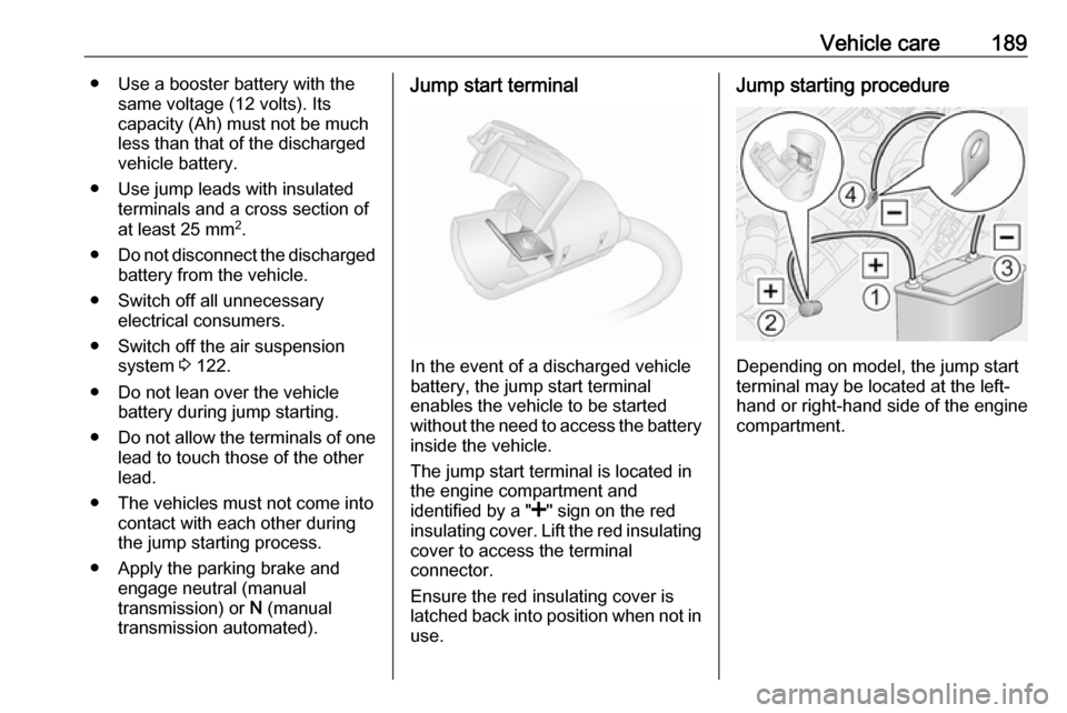
Jump starting procedure
Depending on model, the jump start
terminal may be located at the left-
hand or right-hand side of the engine
compartment.
Page 192 of 233
190Vehicle care
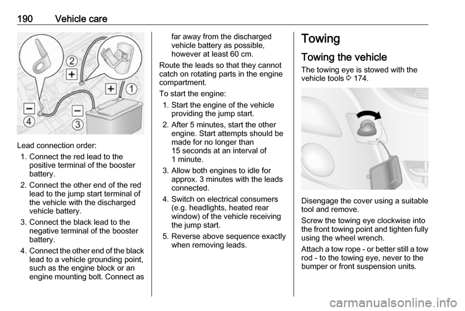
Lead connection order:1. Connect the red lead to the positive terminal of the booster
battery.
2. Connect the other end of the red lead to the jump start terminal of
the vehicle with the discharged
vehicle battery.
3. Connect the black lead to the negative terminal of the booster
battery.
4. Connect the other end of the black
lead to a vehicle grounding point,
such as the engine block or an
engine mounting bolt. Connect as
far away from the discharged
vehicle battery as possible,
however at least 60 cm.
Route the leads so that they cannot
catch on rotating parts in the engine
compartment.
To start the engine: 1. Start the engine of the vehicle providing the jump start.
2. After 5 minutes, start the other engine. Start attempts should be
made for no longer than
15 seconds at an interval of
1 minute.
3. Allow both engines to idle for approx. 3 minutes with the leads
connected.
4. Switch on electrical consumers (e.g. headlights, heated rear
window) of the vehicle receiving
the jump start.
5. Reverse above sequence exactly when removing leads.Towing
Towing the vehicle
The towing eye is stowed with the vehicle tools 3 174.
Disengage the cover using a suitable
tool and remove.
Screw the towing eye clockwise into
the front towing point and tighten fully using the wheel wrench.
Attach a tow rope - or better still a tow
rod - to the towing eye, never to the
bumper or front suspension units.