Page 545 of 668
5458-2. Steps to take in an emergency
SIENNA_OM_OM08013U_(U)
8
When trouble arises
■SRS warning light
This warning light system monitors the airbag sensor assembly, front impact
sensors, side impact sensors (front door), side impact sensors (rear), driver’s
seat position sensor, driver’s seat belt buckle switch, front passenger occu-
pant classification system (ECU and sensors), “AIR BAG ON” indicator light,
“AIR BAG OFF” indicator light, front passenger’s seat belt buckle switch, seat
belt assemblies, airbags, interconnecting wiring and power sources. ( P. 36)
■ Front passenger detection sensor, seat belt reminder and warning
buzzer
● If luggage is placed on the front passenger seat, the front passenger detec-
tion sensor may cause the warning light to flash and the warning buzzer to
sound even if a passenger is not sitting in the seat.
● If a cushion is placed on the seat, the sensor may not detect a passenger,
and the warning light may not operate properly.
■ If the malfunction indicator la mp comes on while driving
First check the following:
● Is the fuel tank empty?
If it is, fill the fuel tank immediately.
● Is the fuel tank cap loose?
If it is, tighten it securely.
The light will go off after several driving trips.
If the light does not go off even after several trips, contact your Toyota dealer
as soon as possible.
■ Electric power steering system warning light (warning buzzer)
When the battery charge becomes insufficient or the voltage temporarily
drops, the electric power steering system warning light may come on and the
warning buzzer may sound.
■
When the tire pressure warning light comes on
Check the tire inflation pressure and adjust to the appropriate level. Push-
ing the tire pressure warning reset switch will not turn off the tire pressure
warning light.
■The tire pressure warning light may come on due to natural causes
The tire pressure warning light may come on due to natural causes such
as natural air leaks and tire inflation pressure changes caused by temper-
ature. In this case, adjusting the ti re inflation pressure will turn off the
warning light (after a few minutes).
Page 564 of 668
5648-2. Steps to take in an emergency
SIENNA_OM_OM08013U_(U)
Once
Sounds
once for
5 sec-
onds
• An attempt was made to lockthe doors using the smart key
system while the electronic
key was still inside the vehi-
cle.
• An attempt was made to lock either front door by opening a
door and putting the inside
lock button into the lock posi-
tion, then closing the door
with the electronic key still
inside the vehicle.
Retrieve the electronic key
from the vehicle and lock
the doors again.
Once
• When the doors were
unlocked with the mechanical
key and then the engine
switch was pressed, the elec-
tronic key could not be
detected in the vehicle.
• The electronic key could not
be detected in the vehicle
even after the engine switch
was pressed two consecu-
tive times.
Touch the electronic key to
the engine switch while
depressing the brake
pedal.
Interior
buzzerExterior buzzerWarning messageDetails/Actions
(Flashes)
(Flashes)
Page 578 of 668
5788-2. Steps to take in an emergency
SIENNA_OM_OM08013U_(U)
Pull strap to tighten and secure
tire.
Lay down the tire with the outer
side (valve stem) facing up, and
install the holding bracket.
Turn the jack handle clockwise
to raise the tire until the tire is in
the correct position as the jack
handle skips.
Stow the tools.5
Stowing the spare tire
Valve stem1
2
3
Page 580 of 668
5808-2. Steps to take in an emergency
SIENNA_OM_OM08013U_(U)
WARNING
■When using the compact spare tire
●Remember that the compact spare tire provided is specifically
designed for use with your vehicle. Do not use your compact spare tire
on another vehicle.
●Do not use more than one compact spare tire simultaneously.
●Replace the compact spare tire with a standard tire as soon as possi-
ble.
●Avoid sudden acceleration, abrupt steering, sudden braking and shift-
ing operations that cause sudden engine braking.
■When the compact spare tire is attached
The vehicle speed may not be correctly detected, and the following sys-
tems may not operate correctly:
Also, not only can the following system not be utilized fully, but it may
even negatively affect the drive-train components:
• AWD system (if equipped)
■Speed limit when using the compact spare tire
Do not drive at speeds in excess of 50 mph (80 km/h) when a compact
spare tire is installed on the vehicle.
The compact spare tire is not designed for driving at high speeds. Fail-
ure to observe this precaution may lead to an accident causing death or
serious injury.
■After using the tools and jack
Before driving, make sure all the tools and jack are securely in place in
their storage location to reduce the po ssibility of personal injury during a
collision or sudden braking.
■When stowing the flat tire
●Make sure the third seats are in their original position.
●Secure it using a tire strap. Otherwise, the flat tire may fly out in case
of sudden braking or an accident, resulting in death or serious injury.
• ABS & Brake assist
• VSC
•TRAC
• Dynamic radar cruise control (if equipped) • Cruise control (if equipped)
• PCS (if equipped)
• Navigation system (if equipped)
Page 581 of 668
5818-2. Steps to take in an emergency
SIENNA_OM_OM08013U_(U)
8
When trouble arises
NOTICE
■When loosening or tightening the spare tire clamp bolt
Do not use an impact wrench. Use the adapter socket and jack handle.
■Be careful when driving over bumps with the compact spare tire
installed on the vehicle
The vehicle becomes lower when driving with the compact spare tire
compared to when driving with standard tires. Be careful when driving
over uneven road surfaces.
■Driving with tire chains and the compact spare tire
Do not fit tire chains to the compact spare tire.
Tire chains may damage the vehicle body and adversely affect driving
performance.
■When replacing the tires
When removing or fitting the wheels, tires or the tire pressure warning
valve and transmitter, contact your Toyota dealer as the tire pressure
warning valve and transmitter may be damaged if not handled correctly.
■To avoid damage to the tire pressure warning valves and transmit-
ters
When a tire is repaired with liquid sealants, the tire pressure warning
valve and transmitter may not operate properly. If a liquid sealant is
used, contact your Toyota dealer or other qualified service shop as soon
as possible. Make sure to replace the tire pressure warning valve and
transmitter when replacing the tire. ( P. 493)
■After taking out or stowing the spare tire
Make sure to secure the tire carrier by tightening the clamp bolt to pre-
vent the holding bracket from hitting the under body of the vehicle dur-
ing driving.
■Using the tire carrier
●As the tire carrier is designed for use with the compact spare tire, it
cannot be used with standard tires.
●If the spare tire is flat, do not use t he tire carrier, as the tire may not be
held securely.
Page 588 of 668
5888-2. Steps to take in an emergency
SIENNA_OM_OM08013U_(U)
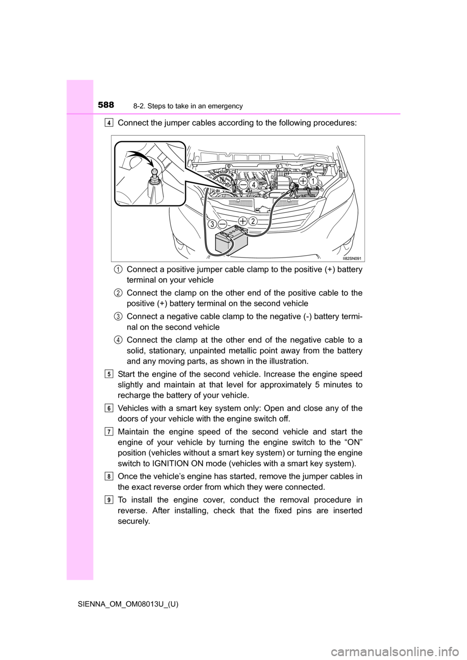
Connect the jumper cables according to the following procedures:Connect a positive jumper cable clamp to the positive (+) battery
terminal on your vehicle
Connect the clamp on the other e nd of the positive cable to the
positive (+) battery terminal on the second vehicle
Connect a negative cable clamp to the negative (-) battery termi-
nal on the second vehicle
Connect the clamp at the other end of the negative cable to a
solid, stationary, unpainted metallic point away from the battery
and any moving parts, as shown in the illustration.
Start the engine of the second vehicle. Increase the engine speed
slightly and maintain at that le vel for approximately 5 minutes to
recharge the batter y of your vehicle.
Vehicles with a smart key system only: Open and close any of the
doors of your vehicle with the engine switch off.
Maintain the engine speed of t he second vehicle and start the
engine of your vehicle by turni ng the engine switch to the “ON”
position (vehicles without a smart key system) or turning the engine
switch to IGNITION ON mode (v ehicles with a smart key system).
Once the vehicle’s engine has started, remove the jumper cables in
the exact reverse order from which they were connected.
To install the engine cover, conduct the removal procedure in
reverse. After installing, check that the fixed pins are inserted
securely.4
1
2
3
4
5
6
7
8
9
Page 620 of 668
620
SIENNA_OM_OM08013U_(U)
9-1. Specifications
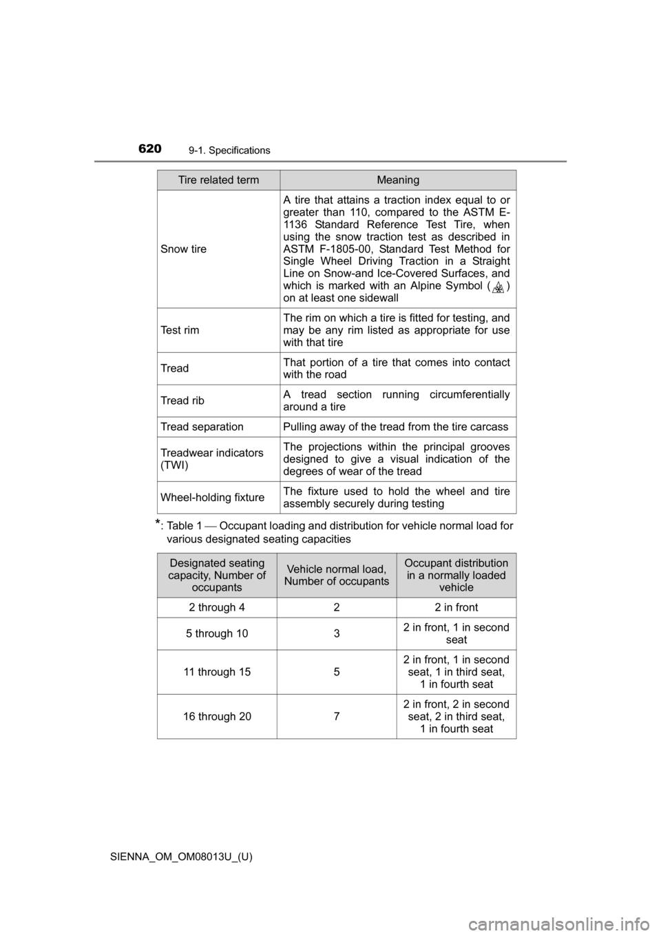
*: Table 1 Occupant loading and distribution for vehicle normal load for
various designated seating capacities
Snow tire
A tire that attains a traction index equal to or
greater than 110, compared to the ASTM E-
1136 Standard Reference Test Tire, when
using the snow traction test as described in
ASTM F-1805-00, Standard Test Method for
Single Wheel Driving Traction in a Straight
Line on Snow-and Ice-Covered Surfaces, and
which is marked with an Alpine Symbol ( )
on at least one sidewall
Test rim The rim on which a tire is fitted for testing, and
may be any rim listed as appropriate for use
with that tire
Tread That portion of a tire that comes into contact
with the road
Tread rib A tread section running circumferentially
around a tire
Tread separation Pulling away of th e tread from the tire carcass
Treadwear indicators
(TWI) The projections within the principal grooves
designed to give a visual indication of the
degrees of wear of the tread
Wheel-holding fixture The fixture used to hold the wheel and tire
assembly securely
during testing
Tire related termMeaning
Designated seating
capacity, Number of occupantsVehicle normal load,
Number of occupantsOccupant distribution
in a normally loaded vehicle
2 through 4 2 2 in front
5 through 10 32 in front, 1 in second
seat
11 through 15 52 in front, 1 in second
seat, 1 in third seat, 1 in fourth seat
16 through 20 72 in front, 2 in second
seat, 2 in third seat, 1 in fourth seat
Page 627 of 668
SIENNA_OM_OM08013U_(U)
6279-2. Customization
9
Vehicle specifications
■Smart key system* ( P. 143)
*: If equipped
■
Wireless remote control ( P. 105)
*: If equipped
FunctionDefault settingCustomized
setting
Smart key system OnOff O – O
Number of consecutive
door lock operations 2 timesAs many as
desired ––O
123
FunctionDefault settingCustomized
setting
Wireless remote control OnOff – – O
Unlocking operation Driver’s door
unlocked in
one step, all
doors unlocked
in two steps All doors
unlocked in one step O–O
Power sliding door
operation
*Press and hold
Off
––O
Press twice
One short press
Power back door
operation
*Press and hold
Off
––O
Press twice
One short press
Alarm (panic mode) OnOff – – O
123