2016 SUBARU WRX power steering
[x] Cancel search: power steeringPage 423 of 594

Starting and operating/Power steering
& Except STI
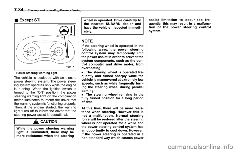
Power steering warning light
The vehicle is equipped with an electric
power steering system. The power steer-
ing system operates only while the engine
is running. When the ignition switch is
turned to the “ ON ” position, the power
steering warning light on the combination
meter illuminates to inform the driver that
the warning system is functioning properly.
Then, if the engine started, the warning
light turns off to inform the driver that the
steering power assist is operational.
CAUTION
While the power steering warning
light is illuminated, there may be
more resistance when the steering wheel is operated. Drive carefully to
the nearest SUBARU dealer and
have the vehicle inspected immedi-
ately.
NOTE If the steering wheel is operated in the
following ways, the power steering
control system may temporarily limit
the power assist in order to prevent the
system components, such as the con-
trol computer and drive motor, from
overheating.
. The steering wheel is operated fre-
quently and turned sharply while the
vehicle is maneuvered at extremely low
speeds, such as while frequently turn-
ing the steering wheel during parallel
parking.
. The steering wheel remains in the
fully turned position for a long period
of time.
At this time, there will be more resis-
tance when steering. However this is
not a malfunction. Normal steering
force will be restored after the steering
wheel is not operated for a while and
the power steering control system has
an opportunity to cool down. However,
if the power steering is operated in a
non-standard way which causes power assist limitation to occur too fre-
quently, this may result in a malfunc-
tion of the power steering control
system.
7-34
Page 428 of 594

namics Control is no guarantee
that full vehicle control will be
maintained at all times and under
all conditions, its activation
should be seen as a sign that
the speed of the vehicle should
be reduced considerably.
. Whenever suspension compo-
nents, steering components, or
an axle are removed from a
vehicle, have an inspection of
that system performed by an
authorized SUBARU dealer.
. The following precautions should
be observed in order to ensure
that the Vehicle Dynamics Con-
trol system is operating properly:
– All four wheels should be
fitted with tires of the same
size, type, and brand. Further-
more, the amount of wear
should be the same for all
four tires.
– Keep the tire pressure at the
proper level as shown on the
vehicle placard attached to
the driver ’ s side door pillar.
– Use only the specified tem-
porary spare tire to replace a
flat tire. With a temporary
spare tire, the effectiveness of the Vehicle Dynamics Con-
trol system is reduced and
this should be taken into ac-
count when driving the vehi-
cle in such a condition.
. If non-matching tires are used,
the Vehicle Dynamics Control
system may not operate cor-
rectly.
. The Vehicle Dynamics Control
system helps prevent unstable
vehicle motion such as skidding
using control of the brakes and
engine power. Do not turn off the
Vehicle Dynamics Control sys-
tem unless it is absolutely ne-
cessary. If you must turn off the
Vehicle Dynamics Control sys-
tem, drive very carefully accord-
ing to the road surface condition.
In the event of wheelspin and/or skidding
on a slippery road surface and/or during
cornering and/or an evasive maneuver,
the Vehicle Dynamics Control system
adjusts the engine ’ s output and the
wheels ’ respective braking forces to help
maintain traction and directional control.
. Traction Control Function
The traction control function is designed to
prevent spinning of the driving wheels on slippery road surfaces, thereby helping to
maintain traction and directional control.
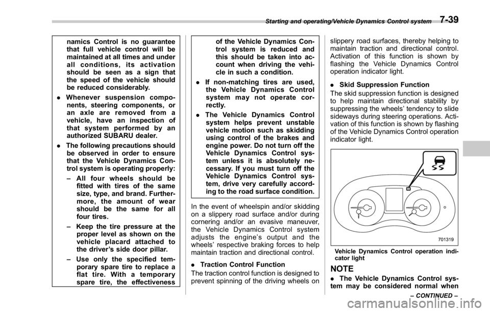
Activation of this function is shown by
flashing the Vehicle Dynamics Control
operation indicator light.
. Skid Suppression Function
The skid suppression function is designed
to help maintain directional stability by
suppressing the wheels ’ tendency to slide
sideways during steering operations. Acti-
vation of this function is shown by flashing
of the Vehicle Dynamics Control operation
indicator light.
Vehicle Dynamics Control operation indi-
cator light
NOTE
. The Vehicle Dynamics Control sys-
tem may be considered normal whenStarting and operating/Vehicle Dynamics Control system
– CONTINUED –7-39
Page 480 of 594

position for CVT models. Shift the shift
lever into the “ 1st ” position for MT models.
2. Apply the parking brake firmly.
3. Secure the vehicle onto the carrier
properly with safety chains. Each safety
chain should be equally tightened and
care must be taken not to pull the chains
so tightly that the suspension bottoms out.
CAUTIONIf your vehicle has a front under-
spoiler and rear underspoiler (both
optional), be careful not to scrape
them when placing the vehicle on
the carrier and when removing the
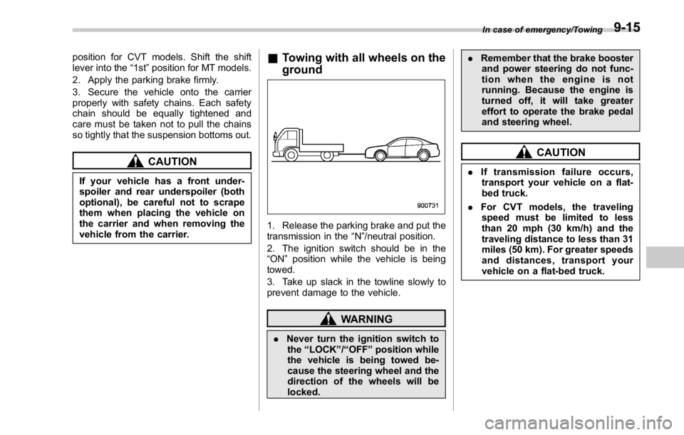
vehicle from the carrier. & Towing with all wheels on the
ground
1. Release the parking brake and put the
transmission in the “ N ” /neutral position.
2. The ignition switch should be in the
“ ON ” position while the vehicle is being
towed.
3. Take up slack in the towline slowly to
prevent damage to the vehicle.
WARNING
. Never turn the ignition switch to
the “ LOCK ” / “ OFF ” position while
the vehicle is being towed be-
cause the steering wheel and the
direction of the wheels will be
locked. . Remember that the brake booster
and power steering do not func-
tion when the engine is not
running. Because the engine is
turned off, it will take greater
effort to operate the brake pedal
and steering wheel.
CAUTION. If transmission failure occurs,
transport your vehicle on a flat-
bed truck.
. For CVT models, the traveling
speed must be limited to less
than 20 mph (30 km/h) and the
traveling distance to less than 31
miles (50 km). For greater speeds
and distances, transport your
vehicle on a flat-bed truck. In case of emergency/Towing
9-15
Page 490 of 594

Maintenance schedule ....................................... 11-3
Maintenance precautions ................................... 11-3Before checking or servicing in the engine
compartment .................................................... 11-4
When checking or servicing in the engine
compartment .................................................... 11-5
When checking or servicing in the engine
compartment while the engine is running .......... 11-5
Maintenance tips ................................................ 11-6Removing and reinstalling clips .......................... 11-6
Engine hood ....................................................... 11-9
Engine compartment overview ........................ 11-11STI................................................................... 11-11
Except STI ....................................................... 11-12
Engine oil .......................................................... 11-13Engine oil consumption .................................... 11-13
Checking the oil level ....................................... 11-13
Changing the oil and oil filter ............................ 11-15
Recommended grade and viscosity .................. 11-16
Synthetic oil ..................................................... 11-16
Cooling system ................................................ 11-17Cooling fan, hose and connections ................... 11-17
Engine coolant ................................................. 11-18
Air cleaner element .......................................... 11-19
Replacing the air cleaner element ..................... 11-19
Spark plugs ...................................................... 11-21
Recommended spark plugs .............................. 11-21
Drive belts ........................................................ 11-22
Manual transmission oil .................................. 11-23
Recommended grade and viscosity .................. 11-23 Continuously variable transmission fluid ...... 11-23
Front differential gear oil (CVT models) and
rear differential gear oil ................................ 11-23Recommended grade and viscosity .................. 11-23
Power steering fluid (STI) ............................... 11-24Checking the fluid level .................................... 11-24
Recommended fluid ......................................... 11-24
Brake fluid ........................................................ 11-25Checking the fluid level .................................... 11-25
Recommended brake fluid ............................... 11-25
Clutch fluid (MT models) ................................. 11-26Checking the fluid level .................................... 11-26
Recommended clutch fluid ............................... 11-26
Brake booster .................................................. 11-27
Brake pedal ...................................................... 11-27Checking the brake pedal free play .................. 11-27
Checking the brake pedal reserve distance ....... 1 1-28
Clutch pedal (MT models) ............................... 11-28Checking the clutch function ............................ 11-28
Checking the clutch pedal free play .................. 11-28
Hill start assist system .................................... 11-29
Replacement of brake pad and lining ............ 11-29Breaking-in of new brake pads (models with
electronic parking brake system) .................... 11-29
Breaking-in of new brake pads and linings
(models without electronic parking brake
system) ......................................................... 11-30
Parking brake stroke (models without
electronic parking brake system) ................ 11-30Maintenance and service
11
Page 500 of 594

Engine compartment overview & STI 1) Power steering fluid reservoir
(page 11-24)
2) Brake fluid reservoir/Clutch fluid reservoir
(page 11-25)
3) Fuse box (page 11-42)
4) Battery (page 11-41)
5) Windshield washer tank (page 11-38)
6) Engine oil filler cap (page 11-13)
7) Engine coolant reservoir (page 11-18)
8) Engine oil level gauge (page 11-13)
9) Coolant filler tank cap (page 11-18)
10) Air cleaner case (page 11-19)Maintenance and service/Engine compartment overview
– CONTINUED –11-11
Page 511 of 594

Maintenance and service/Drive belts
Drive belts NOTE For models except STI, it is unneces-
sary to check the deflection of the drive
belt periodically because this engine is
equipped with an automatic belt ten-
sion adjuster. However, replacement of
the belt should be done according to
the maintenance schedule in the “ War-
ranty and Maintenance Booklet ” . Con-
sult your SUBARU dealer for replace-
ment.
If the drive belt is loose, cracked or
worn, contact your SUBARU dealer. STI
1) Power steering oil pump pulley
2) Front side belt
3) Alternator pulley
4) Air conditioner compressor pulley
5) Rear side belt
6) Crank pulley
A) 22 lbf (98 N, 10 kgf)
CAUTION
The front side belt, which runs in
conjunction with the following com-
ponents, must be used within the
specified deflection.
. Power steering oil pump pulley
. Alternator pulley
. Crank pulley
Check the deflection of the front side belt and if there is any loosen-
ess, cracks, wear or unusual noise
on the front side belt, contact your
SUBARU dealer.
Continuing to use the vehicle with
the belt outside of the specification
may cause the engine to malfunc-
tion and the above components to
malfunction.
To check the deflection of the front side
belt, place a straightedge (ruler) across
two adjacent pulleys (alternator pulley and
crank pulley) and apply a force of 22 lbf
(98 N, 10 kgf) midway between the pulleys
by using a spring scale. The belt deflec-
tion should be the amount specified. If the
front side belt is loose, cracked or worn,
contact your SUBARU dealer. in (mm)
Deflection
New belt
Used belt
A 0.28 – 0.35
(7.0 – 9.0) 0.35 – 0.43
(9.0 – 11.0)
The rear side belt is a stretch-type belt,
therefore the deflection does not need to
be checked. If there are cracks or wear
confirmed on the belts and a squeaking
noise is heard from them, contact your
SUBARU dealer.11-22
Page 513 of 594

Maintenance and service/Power steering fluid (STI)
Power steering fluid (STI) & Checking the fluid level
The power steering fluid expands greatly
as its temperature rises; the fluid level
differs according to fluid temperature.
Therefore, the reservoir tank has two
different checking ranges for hot and cold
fluids.
Check the power steering fluid level
monthly.
1. Park the vehicle on a level surface,
and stop the engine.
2. Check the fluid level of the reservoir
tank.
When the fluid is hot after the vehicle has
been run: Check that the oil level is
between “ HOT MIN ” and “ HOT MAX ” on the surface of the reservoir tank.
When the fluid is cool before the vehicle is
run: Check that the oil level is between
“ COLD MIN ” and “ COLD MAX ” on the
surface of the reservoir tank.
3. If the fluid level is lower than the
applicable “ MIN ” line, add the recom-
mended fluid as necessary to bring the
level between the “ MIN ” and “ MAX ” line.
If the fluid level is extremely low, it may
indicate possible leakage. Consult your
SUBARU dealer for an inspection.
WARNINGBe careful not to burn yourself
because the fluid may be hot.
CAUTION
. When power steering fluid is
being added, use only clean fluid,
and be careful not to allow any
dirt into the tank. And never use
different brands together.
. Be careful not to spill power
steering fluid when adding it. If
power steering fluid touches the
exhaust pipe, it may cause a bad
smell, smoke, and/or a fire. If
power steering fluid gets on the exhaust pipe, be sure to wipe it
off.
& Recommended fluid Refer to “ Fluids ” F 12-7.
11-24
Page 548 of 594

*4: You may use this type of manual transmission oil. However, using this type of oil will detract from driveability and fuel efficiency.
& Fluids Fluid
Fluid type* 1
Fluid capacity* 2
Remarks* 3
Continuously variable transmission
fluid (CVT models) Consult your SUBARU dealer. 13.1 US qt (12.4 liters, 10.9 Imp qt) “ Continuously variable trans-
mission fluid ” F 11-23
Brake fluid FMVSS No. 116, fresh DOT 3 or DOT 4
brake fluid –“ Brake fluid ” F 11-25
Clutch fluid (MT models) FMVSS No. 116, fresh DOT 3 or DOT 4
brake fluid – “ Clutch fluid (MT models) ” F 11 -
26
Power steering fluid (STI) · SUBARU ATF
· “ Dexron III ” Type Automatic Transmis-
sion Fluid
· IDEMITSU ATF HP 0.7 US qt (0.7 liter, 0.6 Imp qt) “ Power steering fluid (STI) ”
F 11-24
*1: Use one of the indicated types of fluid.
*2: The indicated fluid quantity is only a guideline. The necessary quantity for replacement may differ slightly depending on the temperature and other
factors.
*3: For more details about maintenance and service, refer to the indicated section.
& Engine coolant Vehicle model Coolant capacity Coolant type
STI 8.2 US qt (7.7 liters, 6.8 Imp qt)
SUBARU Super Coolant
Except STI MT models 8.7 US qt (8.2 liters, 7.2 Imp qt)
CVT models 8.9 US qt (8.4 liters, 7.4 Imp qt)
The indicated coolant quantity is only a guideline. The necessary quantity for replacement may differ slightly depending on the temperature and other
factors. For more details about maintenance and service, refer to “ Cooling system ” F 11-17. Specifications/Specifications
– CONTINUED –12-7