2016 SUBARU WRX trunk release
[x] Cancel search: trunk releasePage 21 of 594

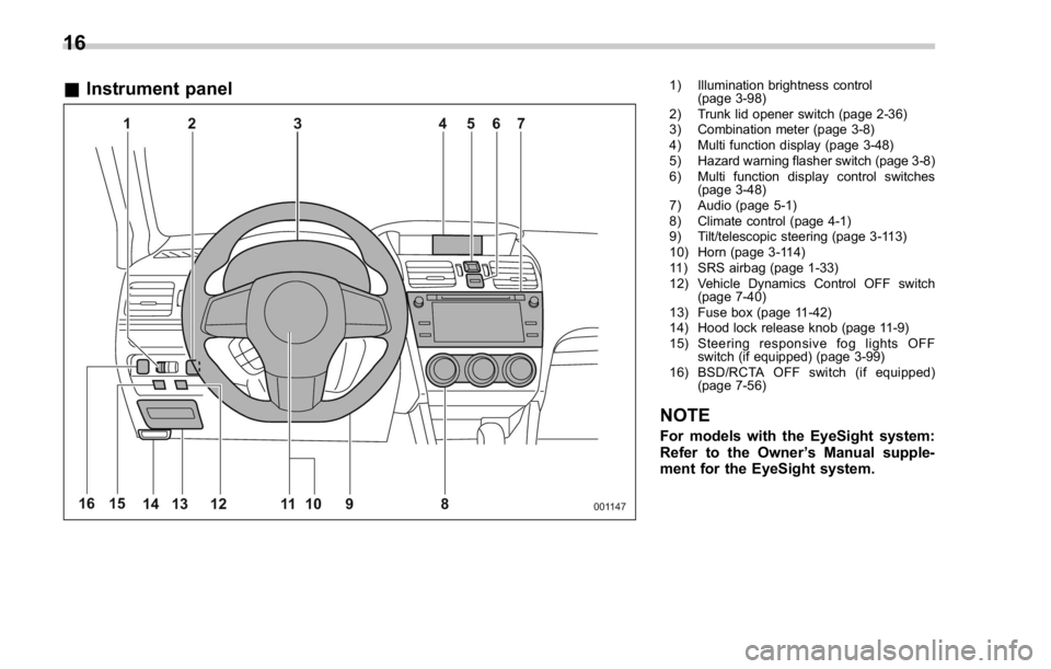
& Instrument panel 1) Illumination brightness control
(page 3-98)
2) Trunk lid opener switch (page 2-36)
3) Combination meter (page 3-8)
4) Multi function display (page 3-48)
5) Hazard warning flasher switch (page 3-8)
6) Multi function display control switches
(page 3-48)
7) Audio (page 5-1)
8) Climate control (page 4-1)
9) Tilt/telescopic steering (page 3-113)
10) Horn (page 3-114)
11) SRS airbag (page 1-33)
12) Vehicle Dynamics Control OFF switch
(page 7-40)
13) Fuse box (page 11-42)
14) Hood lock release knob (page 11-9)
15) Steering responsive fog lights OFF
switch (if equipped) (page 3-99)
16) BSD/RCTA OFF switch (if equipped)
(page 7-56)
NOTE For models with the EyeSight system:
Refer to the Owner ’ s Manual supple-
ment for the EyeSight system.16
Page 38 of 594

cient clearance between the head re-
straint and the roof, tilt the seat and
then perform the installation and re-
moval tasks.
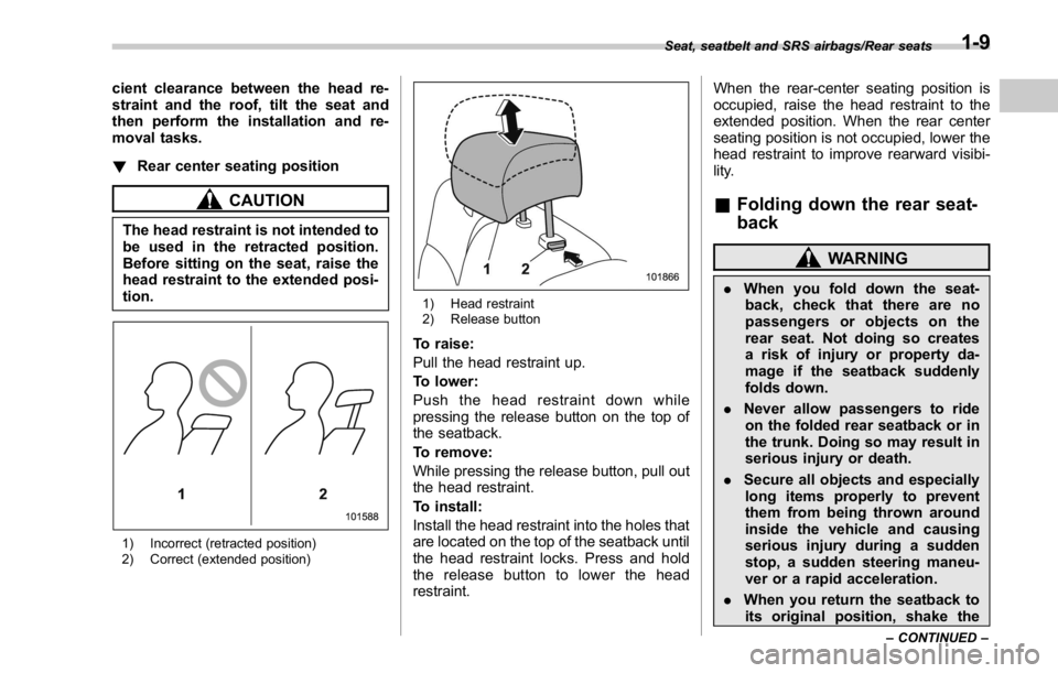
! Rear center seating position
CAUTIONThe head restraint is not intended to
be used in the retracted position.
Before sitting on the seat, raise the
head restraint to the extended posi-
tion.
1) Incorrect (retracted position)
2) Correct (extended position) 1) Head restraint
2) Release button
To raise:
Pull the head restraint up.
To lower:
Push the head restraint down while
pressing the release button on the top of
the seatback.
To remove:
While pressing the release button, pull out
the head restraint.
To install:
Install the head restraint into the holes that
are located on the top of the seatback until
the head restraint locks. Press and hold
the release button to lower the head
restraint. When the rear-center seating position is
occupied, raise the head restraint to the
extended position. When the rear center
seating position is not occupied, lower the
head restraint to improve rearward visibi-
lity.
& Folding down the rear seat-
back WARNING. When you fold down the seat-
back, check that there are no
passengers or objects on the
rear seat. Not doing so creates
a risk of injury or property da-
mage if the seatback suddenly
folds down.
. Never allow passengers to ride
on the folded rear seatback or in
the trunk. Doing so may result in
serious injury or death.
. Secure all objects and especially
long items properly to prevent
them from being thrown around
inside the vehicle and causing
serious injury during a sudden
stop, a sudden steering maneu-
ver or a rapid acceleration.
. When you return the seatback to
its original position, shake the Seat, seatbelt and SRS airbags/Rear seats
– CONTINUED –1-9
Page 39 of 594

Seat, seatbelt and SRS airbags/Rear seats
seatback slightly to confirm that
it is securely fixed in place. If the
seatback is not securely fixed in
place, the seatback may sud-
denly fold down in the event of
sudden braking, or objects may
move out from the trunk, which
could cause serious injury or
death.
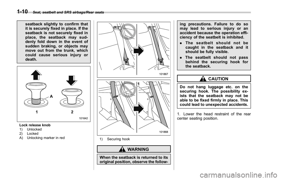
Lock release knob
1) Unlocked
2) Locked
A) Unlocking marker in red
1) Securing hook
WARNING
When the seatback is returned to its
original position, observe the follow- ing precautions. Failure to do so
may lead to serious injury or an
accident because the operation effi-
ciency of the seatbelt is inhibited.
. The seatbelt should not be
caught in the seatback and it
should be fully visible.
. The seatbelt should not pass
behind the securing hook for
the seatback.
CAUTIONDo not hang luggage etc. on the
securing hook. The possibility ex-
ists that the seatback may not be
able to be fixed firmly in place. This
could lead to unexpected accidents.
1. Lower the head restraint of the rear
center seating position.1-10
Page 91 of 594

Keys and doors
To open the trunk lid from inside ........................ 2-36
Internal trunk lid release handle .......................... 2-37
Moonroof (if equipped) ...................................... 2-38Moonroof switches ............................................ 2-39
Sun shade ......................................................... 2-40
Page 99 of 594

Keys and doors/Keyless access with push – button start system
. Opening the trunk
. Starting and stopping the engine. For
detailed information, refer to “ Starting and
stopping engine (models with push-button
start system) ” F 7-12.
. Arming and disarming the alarm sys-
tem. For detailed information, refer to
“ Alarm system ” F 2-25.
Locking and unlocking by the remote
keyless entry system can also be con-
trolled with the buttons on the access key.
For detailed information, refer to “ Remote
keyless entry system ” F 2-21.
A mechanical key is attached to each
access key. The mechanical key is used
for the following operations.
. Locking and unlocking the driver ’ s door
. Locking and unlocking the glove box
You cannot unlock the glove box without
using the mechanical key. You can keep
the glove box locked when you leave your
vehicle and the access key (with the
mechanical key removed) at a parking
facility. 1) Release button
2) Mechanical key
While pressing the release button of the
access key, take out the mechanical key.
& Safety precautions
WARNING
If you wear an implanted pacemaker
or an implanted defibrillator, stay at
least 8.7 in (22 cm) away from the
transmitting antennas installed on
the vehicle.
The radio waves from the transmit-
ting antennas on the vehicle could
adversely affect the operation of
implanted pacemakers and im-
planted defibrillators. If you wear electric medical equip-
ment other than an implanted pace-
maker or an implanted defibrillator,
before using the keyless access
with push-button start system, refer
to “ Radio waves used for the key-
less access with push-button start
system ” mentioned later, and con-
tact the electric medical equipment
manufacturer for more information.
The radio waves from the transmit-
ting antennas on the vehicle could
adversely affect the operation of the
electric medical equipment.
“ Radio waves used for the keyless
access with push-button start sys-
tem ”
. The keyless access with push-
button start system uses radio
waves of the following fre-
quency* in addition to the radio
waves used for the remote key-
less entry system. The radio
waves are periodically output
from the antennas installed on
the vehicle as shown in the
following illustrations.
* Radio frequency: 134 kHz2-10
Page 126 of 594

NOTE The trunk lid will not open when the
select lever is in a position other than
the “ P ” position (CVT models) or the
vehicle is moving.
& Internal trunk lid release
handle The internal trunk lid release handle is a
device designed to open the trunk lid from
inside the trunk. In the event children or
adults become locked inside the trunk, the
handle allows them to open the lid. The
handle is located on the inside of the trunk
lid.
To open the trunk lid from inside the trunk,
pull the yellow handle as indicated by the
arrow on the handle. This operation unlocks the trunk lid. Then, push up the
lid.
The handle is made of material that
remains luminescent for approximately
an hour in the dark trunk space after it is
exposed to ambient light even for a short
time.
WARNINGNever allow any child to get in the
trunk and play with the release
handle. If the driver starts the vehi-
cle without knowing that a child is
inside the trunk and the child opens
the lid using the release handle, the
child could fall out and be killed or
seriously injured.
CAUTION
. Do not close the lid while grip-
ping the release handle. The
handle may be damaged.
. Do not use the handle as a hook
to fasten straps or ropes to
secure your cargo in the trunk.
Such use may result in damage
of the handle.
. Load the trunk so that cargo
cannot strike the release handle. If the cargo hits the handle while
the vehicle is being driven, the
handle may be pulled and the
trunk lid may open. That may
cause cargo to fall out of the
trunk, which could create a traffic
safety hazard.
! Inspection
Perform the following steps at least twice
a year to check the release handle for
correct operation.
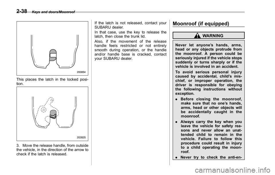
1. Open the trunk lid.
2. Use a flat-head screwdriver with a thin
blade. Slide the flat-head screwdriver
blade from the slit aperture of the lock
assembly fully to the end until you hear a
click. Keys and doors/Trunk lid
– CONTINUED –2-37
Page 127 of 594

Keys and doors/Moonroof
This places the latch in the locked posi-
tion.
3. Move the release handle, from outside
the vehicle, in the direction of the arrow to
check if the latch is released. If the latch is not released, contact your
SUBARU dealer.
In that case, use the key to release the
latch, then close the trunk lid.
Also, if the movement of the release
handle feels restricted or not entirely
smooth during operation, or the handle
and/or handle base is cracked, contact
your SUBARU dealer.
Moonroof (if equipped) WARNINGNever let anyone ’ shands,arms,
head or any objects protrude from
the moonroof. A person could be
seriously injured if the vehicle stops
suddenly or turns sharply or if the
vehicle is involved in an accident.
To avoid serious personal injury
caused by accidental, child ’ s mis-
chief, or improper operation, the
driver is responsible for obeying
the following instructions without
exception.
. Before closing the moonroof,
make sure that no one ’ s hands,
arms, head or other objects will
be accidentally caught in the
moonroof.
. Always carry the key when you
leave the vehicle for safety rea-
sons and never allow an unat-
tended child to remain in the
vehicle. Failure to follow this
procedure could result in injury
to a child operating the moon-
roof.
. Never try to check the anti-en-2-38
Page 435 of 594

Starting and operating/Parking your vehicle
switch is operated, a chirp sound is
heard and the electronic parking brake
indicator light flashes.
. When you cannot release the park-
ing brake due to, for example, a system
malfunction, contact your SUBARU
dealer and have your SUBARU dealer
release the parking brake.
. If the operation of the electronic
parking brake switch is stopped mid-
way or performed extremely slowly, the
system may detect an error and turn on
the brake system warning light. How-
ever, this does not indicate a malfunc-
tion if the brake system warning light
turns off after operating the switch.
. When the electronic parking brake
has not been used for a long period of
time, the electronic parking brake may
operate automatically after the ignition
switch is turned to the “ LOCK ” / “ OFF ”
position. This occurs due to checking
the proper operation of the electronic
parking brake and does not indicate a
malfunction.
. If the electronic parking brake
switch is malfunctioning and the elec-
tronic parking brake cannot be re-
leased, refer to the instructions de-
scribed in “ Automatic release function
by accelerator pedal ” F 7-46.
After activating the EPB, you may hear a short sound several minutes after the
electronic parking brake indicator light
illuminates as the system confirms
proper engagement. This sound is
different from the apply and release
sound.
This can occur:
– If the brakes are extremely hot.
– If the car is parked on a steep
incline.
– If the electronic parking brake is
applied after the ignition switch is
turned OFF.
This is a normal operating sound under
any of these conditions.
! Automatic release function by ac-
celerator pedal
The electronic parking brake system has
an automatic release function. The park-
ing brake will be automatically released by
depressing the accelerator pedal. How-
ever, the automatic release function does
not operate under the following conditions.
. Any door (other than the trunk lid) is
open.
. The driver ’ s seatbelt is not fastened.
If the parking brake is automatically
released, the electronic parking brake
indicator light and the indicator light on the parking brake switch turn off.
NOTE Even if you have applied the parking
brake, the parking brake will be auto-
matically released when the accelera-
tor pedal is depressed.
! Hill Holder function
The electronic parking brake system has a
Hill Holder function. If the Hill Holder
function is activated, the parking brake
will be automatically applied when stop-
ping on an uphill slope with the brake
pedal depressed. In this case, the electro-
nic parking brake indicator light and the
indicator light on the parking brake switch
illuminate.
The Hill Holder function also operates
while driving uphill in reverse.
NOTE . The Hill Holder function may not
activate on a gentle uphill slope. In this
case, manually apply the electronic
parking brake.
. If you do not depress the brake
pedal sufficiently, the Hill Holder func-
tion may not operate properly. How-
ever, this is not a malfunction. When
stopping on an uphill slope, depress
the brake pedal firmly and release it
after the electronic parking brake in-7-46