2016 SUBARU OUTBACK brake
[x] Cancel search: brakePage 7 of 572

&Abbreviation list
You may find several abbreviations in this
manual. The meanings of the abbrevia-
tions are shown in the following list.
Abbreviation Meaning
A/C Air conditioner
ALR/ELRAutomatic locking retractor/
Emergency locking retractor
ABS Anti-lock brake system
AKI Anti knock index
ALR Automatic locking retractor
AWD All-wheel drive
BSD Blind Spot Detection
CVTContinuously variable trans-
mission
DRL Daytime running light
EBDElectronic brake force distri-
bution
ELR Emergency locking retractor
FWD Front-wheel drive
GAW Gross axle weight
GAWR Gross axle weight rating
GPS Global positioning system
GVW Gross vehicle weight
GVWR Gross vehicle weight rating
HID High intensity dischargeAbbreviation Meaning
INT Intermittent
LATCHLower anchors and tethers for
children
LCA Lane Change Assist
LED Light emitting diode
LSD Limited slip differential
MIL Malfunction indicator light
MMTMethylcyclopentadienyl man-
ganese tricarbonyl
MT Manual transmission
OBD On-board diagnostics
RON Research octane number
RCTA Rear Cross Traffic Alert
SRFSteering responsive fog lights
system
SRSSupplemental restraint sys-
tem
TIN Tire identification number
TPMSTire pressure monitoring sys-
tem
Vehicle symbols
There are some of the symbols you may
see on your vehicle.
For warning and indicator lights, refer to
“Warning and indicator lights”F23.
Mark Name
WARNING
CAUTION
Read these instructions care-
fully
Wear eye protection
Battery fluid contains sulfuric
acid
Keep children away
Keep flames away
Prevent explosions
3
Page 12 of 572
General information
&California proposition 65
warning
WARNING
Engine exhaust, some of its consti-
tuents, and certain vehicle compo-
nents contain or emit chemicals
known to the State of California to
cause cancer and birth defects or
other reproductive harm. In addi-
tion, certain fluids in vehicles and
certain components of product wear
contain or emit chemicals known to
the State of California to cause
cancer and birth defects or other
reproductive harm.
&California Perchlorate Advi-
sory
Certain vehicle components such as air-
bag modules, seatbelt pretensioners and
keyless entry transmitter batteries may
contain perchlorate material. Special
handling may apply for service or vehicle
end of life disposal. See www.dtsc.ca.gov/
hazardouswaste/perchlorate.
&Noise from under the vehicle
NOTE
You may hear a noise from under the
vehicle approximately 5 to 10 hours
after the engine is turned off. However,
this does not indicate a malfunction.
This noise is caused by the operation
of the fuel evaporation leakage check-
ing system and the operation is normal.
The noise will stop after approximately
15 minutes.
&Event data recorder
This vehicle is equipped with an event
data recorder (EDR). The main purpose of
an EDR is to record, in certain crash or
near crash-like situations, such as an air
bag deployment or hitting a road obstacle,
data that will assist in understanding how
a vehicle’s systems performed. The EDR
is designed to record data related to
vehicle dynamics and safety systems for
a short period of time, typically 30 seconds
or less. The EDR in this vehicle is
designed to record such data as:
.How various systems in your vehicle
were operating;
.Whether or not the driver and passen-
ger safety belts were buckled/fastened;
.How far (if at all) the driver was
depressing the accelerator and/or brakepedal; and,
.How fast the vehicle was traveling.
These data can help provide a better
understanding of the circumstances in
which crashes and injuries occur. NOTE:
EDR data are recorded by your vehicle
only if a non-trivial crash situation occurs;
no data are recorded by the EDR under
normal driving conditions and no personal
data (e.g., name, gender, age, and crash
location) are recorded. However, other
parties, such as law enforcement, could
combine the EDR data with the type of
personally identifying data routinely ac-
quired during a crash investigation.
To read data recorded by an EDR, special
equipment is required, and access to the
vehicle or the EDR is needed. In addition
to the vehicle manufacturer, other parties,
such as law enforcement, that have the
special equipment, can read the informa-
tion if they have access to the vehicle or
the EDR.
8
Page 17 of 572
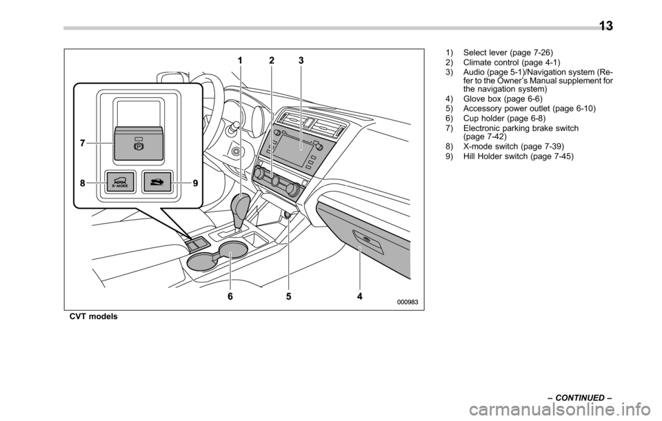
CVT models1) Select lever (page 7-26)
2) Climate control (page 4-1)
3) Audio (page 5-1)/Navigation system (Re-
fer to the Owner’s Manual supplement for
the navigation system)
4) Glove box (page 6-6)
5) Accessory power outlet (page 6-10)
6) Cup holder (page 6-8)
7) Electronic parking brake switch
(page 7-42)
8) X-mode switch (page 7-39)
9) Hill Holder switch (page 7-45)
–CONTINUED–
13
Page 18 of 572
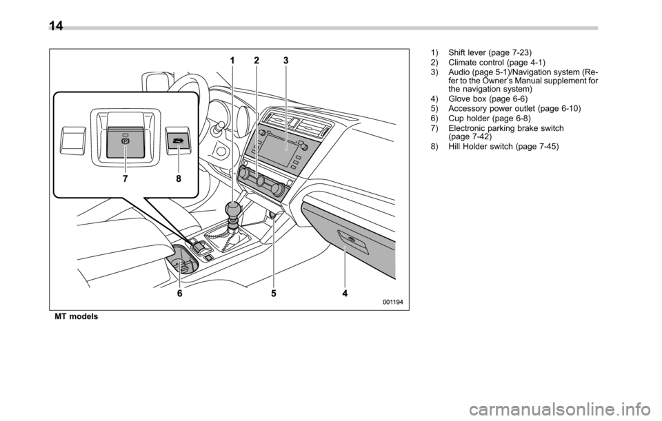
MT models1) Shift lever (page 7-23)
2) Climate control (page 4-1)
3) Audio (page 5-1)/Navigation system (Re-
fer to the Owner’s Manual supplement for
the navigation system)
4) Glove box (page 6-6)
5) Accessory power outlet (page 6-10)
6) Cup holder (page 6-8)
7) Electronic parking brake switch
(page 7-42)
8) Hill Holder switch (page 7-45)
14
Page 27 of 572

&Warning and indicator lights
Mark Name Page
Seatbelt warning light 3-12
Front passenger’s
seatbelt warning light3-12
SRS airbag system
warning light3-14
CHECK ENGINE warn-
ing light/Malfunction in-
dicator light3-15
Charge warning light 3-15
Oil pressure warning
light3-15
Engine low oil level
warning indicator3-16
AT OIL TEMP warning
light (CVT models)3-16
/ABS warning light 3-18
/Brake system warning
light3-18Mark Name Page
/Electronic parking
brake indicator light3-20
Hill Holder indicator
light3-21
Door open indicator 3-22
Low fuel warning light 3-21
All-Wheel Drive warn-
ing light (CVT models)3-22
Power steering warning
light3-22
Vehicle Dynamics Con-
trol warning light/Vehi-
cle Dynamics Control
operation indicator light3-23
Vehicle Dynamics Con-
trol OFF indicator light3-24
Access key warning in-
dicator (if equipped)3-24
Security indicator light 3-29
Turn signal indicator
lights3-30Mark Name Page
High beam indicator
light3-30
Automatic headlight
beam leveler warning
light (if equipped)3-30
Front fog light indicator
light (if equipped)3-31
Cruise control indicator 3-30
Cruise control set indi-
cator3-30
X-mode indicator (if
equipped)3-31
Hill descent control in-
dicator (if equipped)3-31
Headlight indicator light 3-31
Low tire pressure
warning light (U.S.
spec. models)3-16
/Front passenger’s fron-
tal airbag ON indicator
light3-14
/Front passenger’s fron-
tal airbag OFF indicator
light3-14
–CONTINUED–
23
Page 36 of 572
Seat, seatbelt and SRS airbags/Front seats
!Memory function (driver’s seat—if
equipped)
WARNING
.Never adjust the seat while driv-
ing to avoid loss of vehicle con-
trol and personal injury.
.Before adjusting the seat, make
sure that cargo or the hands and
feet of rear seat passengers are
clear of the adjusting mechan-
ism.
.Never retrieve the seat position
while driving to avoid loss of
vehicle control and personal in-
jury.
.Perform the seat position retrie-
val before driving. Be sure to
confirm that the select lever is
in the“P”position, and the
parking brake is applied, when
adjusting the seat position. Do
not drive until the retrieval of the
seat position is complete.
.When retrieving a registered seat
position, make sure the hands,
feet and possessions of rear seat
passengers are clear of the seat
adjusting mechanism.
.When any unusual conditions ormalfunctions occur during the
retrieval of the seat position, stop
the retrieval of the seat position
by performing any of the follow-
ing procedures.
–Operate any of the power seat
switches
–Press the“SET”button
–Press button“1”or“2”
Some of your desired seat positions can
be registered. Register the seat position
with button“1”or“2”or each of the access
keys and retrieve the seat position.
The following seat positions can be
registered.
.Forward/backward position of the seat
.Angle of seatback
.Angle of seat cushion
.Height of seat
!Registration of seat position with
button“1”or“2”
1. Adjust the seat position under the
following conditions.
.The parking brake is applied.
.The select lever is in the“P”posi-
tion.
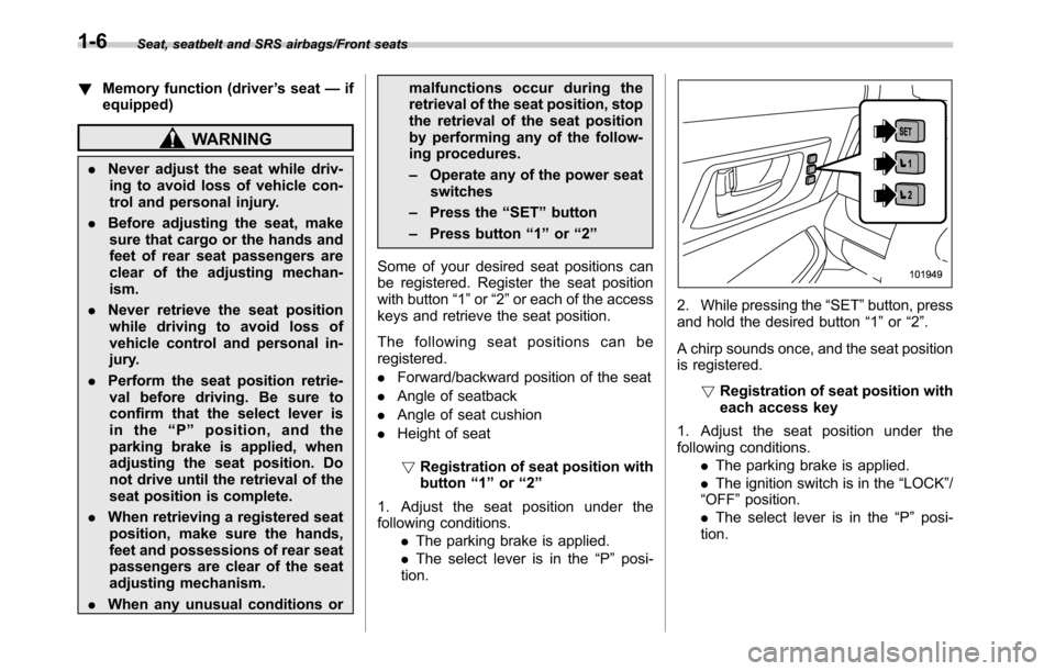
2. While pressing the“SET”button, press
and hold the desired button“1”or“2”.
A chirp sounds once, and the seat position
is registered.
!Registration of seat position with
each access key
1. Adjust the seat position under the
following conditions.
.The parking brake is applied.
.The ignition switch is in the“LOCK”/
“OFF”position.
.The select lever is in the“P”posi-
tion.
1-6
Page 37 of 572
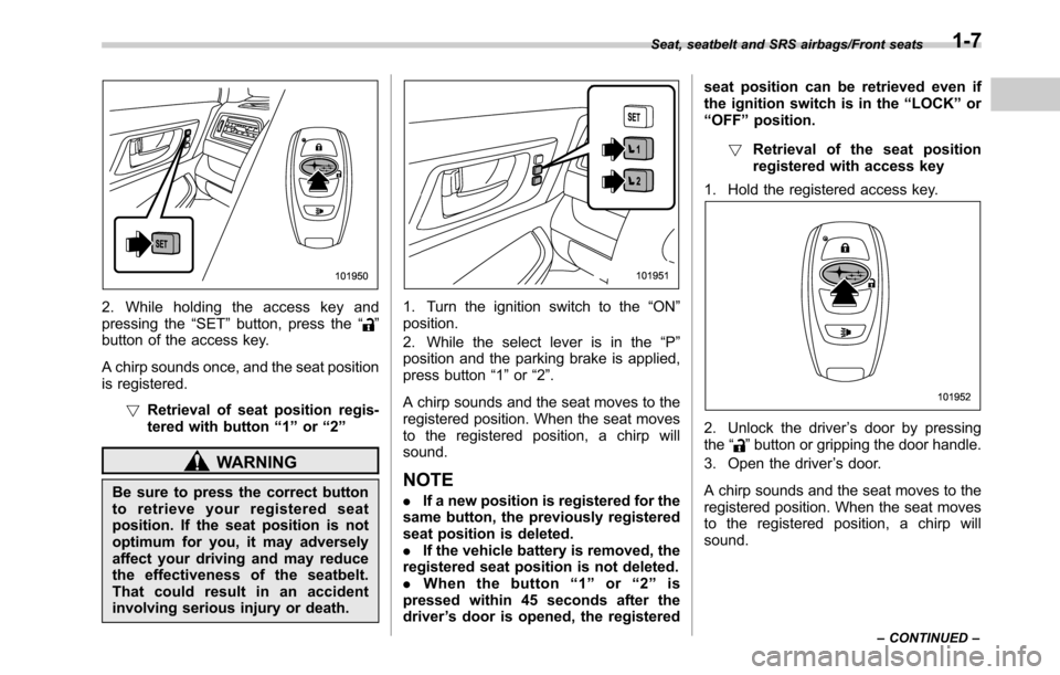
2. While holding the access key and
pressing the“SET”button, press the“”
button of the access key.
A chirp sounds once, and the seat position
is registered.
!Retrieval of seat position regis-
tered with button“1”or“2”
WARNING
Be sure to press the correct button
to retrieve your registered seat
position. If the seat position is not
optimum for you, it may adversely
affect your driving and may reduce
the effectiveness of the seatbelt.
That could result in an accident
involving serious injury or death.
1. Turn the ignition switch to the“ON”
position.
2. While the select lever is in the“P”
position and the parking brake is applied,
press button“1”or“2”.
A chirp sounds and the seat moves to the
registered position. When the seat moves
to the registered position, a chirp will
sound.
NOTE
.If a new position is registered for the
same button, the previously registered
seat position is deleted.
.If the vehicle battery is removed, the
registered seat position is not deleted.
.When the button“1”or“2”is
pressed within 45 seconds after the
driver’s door is opened, the registeredseat position can be retrieved even if
the ignition switch is in the“LOCK”or
“OFF”position.
!Retrieval of the seat position
registered with access key
1. Hold the registered access key.
2. Unlock the driver’s door by pressing
the“”button or gripping the door handle.
3. Open the driver’s door.
A chirp sounds and the seat moves to the
registered position. When the seat moves
to the registered position, a chirp will
sound.
Seat, seatbelt and SRS airbags/Front seats
–CONTINUED–1-7
Page 144 of 572
Keys and doors/Rear gate (Outback)
gate has stopped completely
after opening it.
.Before leaving the vehicle, al-
ways remove the key from the
ignition switch for safety (models
without“keyless access with
push-button start system”) and
never allow an unattended child
to remain in the vehicle. Failure
to follow this procedure could
result in injury to a child operat-
ing the power rear gate.
.The driver should be aware of
and pay careful attention to his/
her responsibilities.
.The power rear gate button
should only be used to open
and close the rear gate when
the area around the rear gate is
clearly visible and when you
have checked that there is no
danger of people being caught in
the gate.
CAUTION
.When closing the rear gate after
opening it, make sure to use the
power rear gate. If you close the
rear gate manually with extra
force, the power rear gate maybe damaged.
.Do not install any accessories
other than genuine SUBARU
parts on the rear gate. If the
weight of rear gate increases
excessively, the rear gate stay
cannot support the rear gate
sufficiently when opening the
rear gate. Also, the power rear
gate may not function properly or
may malfunction.
.Do not touch the driving rod
while the power rear gate oper-
ates or stops. Doing so may
result in injury or damage.
The power rear gate operates only when
all of the following conditions are satisfied.
.The vehicle is stopped completely.
.The outside temperature is within a
range from−228F to 1408F (from−308Cto
608C).
.The ignition switch is in the“LOCK”/
“OFF”or“ACC”position. Or, the ignition
switch is in the“ON”position and the
parking brake is applied (MT models)/the
select lever is in the“P”position (CVT
models).
We recommend using the power rear gate
function in most circumstances instead of
manual operation.
NOTE
.If the power rear gate button is
pressed repeatedly while the power
rear gate is operating, the system may
ignore the button operation in order to
avoid being damaged. Do not press the
button unnecessarily.
.It is not possible to stop the rear
gate temporarily while opening be-
tween the completely closed position
and approximately 12 in (30 cm) open.
If you press one of the power rear gate
buttons briefly during this range, the
rear gate will be closed.
.If the vehicle starts to move while
the power rear gate is operating, the
system sounds a buzzer and closes the
rear gate automatically. At this time, if
the system detects jamming, it will
deactivate the power rear gate and the
rear gate will not be closed. If this
occurs, close the rear gate manually.
.If you try to open the rear gate using
the power rear gate function immedi-
ately after closing the rear gate using
the power rear gate function, an elec-
tronic chirp will sound and the rear
gate will not open. Wait for a while
before trying to open the rear gate via
the power rear gate function.
2-42