2016 SUBARU IMPREZA window
[x] Cancel search: windowPage 244 of 594
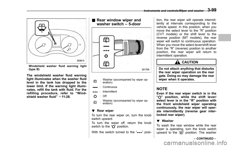
Windshield washer fluid warning light
(type B)
The windshield washer fluid warning
light illuminates when the washer fluid
level in the tank has dropped to the
lower limit. If the warning light illumi-
nates, refill the tank with fluid. For the
refilling procedure, refer to“Wind-
shield washer fluid ”F 11-28.
& Rear window wiper and
washer switch –5-door
: Washer (accompanied by wiper op-
eration)
: Continuous
: Intermittent
: Off
:Washer (accompanied by wiper op-
eration)
!
Rear wiper
To turn the rear wiper on, turn the knob
switch upward.
To turn the wiper off, return the knob
switch to the “
”position.
With the switch turned to the “
”posi- tion, the rear wiper will operate intermit-
tently at intervals corresponding to the
vehicle speed. In this position, when you
move the select lever to the
“R”position
(CVT models) or the shift lever to the
reverse position (MT models), the rear
wiper will switch to continuous operation.
When you move the select lever/shift lever
from the “R”(reverse) position to another
position, the rear wiper will return to
intermittent operation.
CAUTION
Do not attach anything that disturbs
the rear wiper operation on the rear
gate. Doing so may damage the rear
wiper when it operates.
NOTE
Even if the rear wiper switch is in the
“” position, while the shift lever/
select lever is in the “R”position with
the front windshield wiper operating
continuously, the rear wiper will oper-
ate intermittently (reverse gear inter-
locked rear wiper).
! Washer
To wash the rear window while the rear
wiper is operating, turn the knob switch
upward to the “
”position. The washer
Instruments and controls/Wiper and washer
–CONTINUED –3-99
Page 245 of 594
Instruments and controls/Mirrors
fluid sprays until you release the knob.
To wash the rear window when the rear
wiper is not in use, turn the knob switch
downward to the“
”position. The washer
fluid sprays and the wiper operates until
you release the knob.
NOTE
When the amount of washer fluid is
getting low, the rear washer will run out
of fluid before the windshield washer.
This means that the amount of washer
fluid is low, and it should be added
immediately.
Mirrors
Always check that the inside and outside
mirrors are properly adjusted before you
start driving.
& Inside mirror
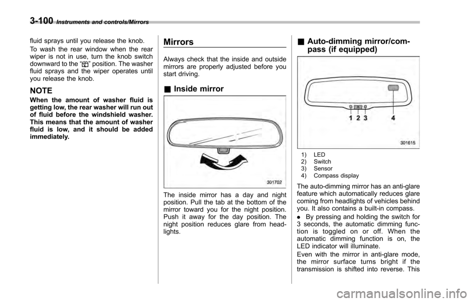
The inside mirror has a day and night
position. Pull the tab at the bottom of the
mirror toward you for the night position.
Push it away for the day position. The
night position reduces glare from head-
lights.
&Auto-dimming mirror/com-
pass (if equipped)
1) LED
2) Switch
3) Sensor
4) Compass display
The auto-dimming mirror has an anti-glare
feature which automatically reduces glare
coming from headlights of vehicles behind
you. It also contains a built-in compass.
. By pressing and holding the switch for
3 seconds, the automatic dimming func-
tion is toggled on or off. When the
automatic dimming function is on, the
LED indicator will illuminate.
Even with the mirror in anti-glare mode,
the mirror surface turns bright if the
transmission is shifted into reverse. This
3-100
Page 246 of 594
is to ensure good rearward visibility during
reversing.
.By pressing and releasing the switch
for less than 3 seconds, the compass
display is toggled on or off. When the
compass is on, an illuminated compass
reading will appear in the upper right
corner of the mirror.
When cleaning the mirror, use a paper
towel or similar material dampened with
glass cleaner. Do not spray glass cleaner
directly on the mirror as that may cause
theliquidcleanertoenterthemirror
housing and damage the mirror.
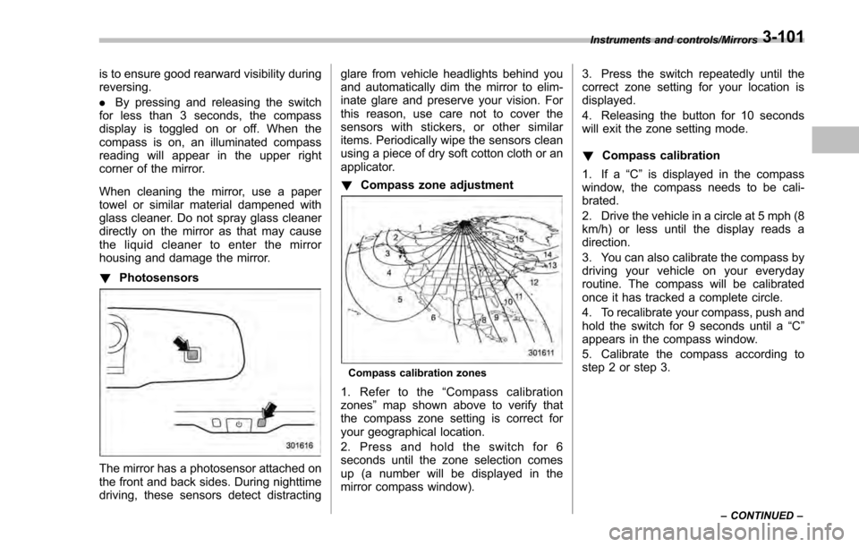
! Photosensors
The mirror has a photosensor attached on
the front and back sides. During nighttime
driving, these sensors detect distracting glare from vehicle headlights behind you
and automatically dim the mirror to elim-
inate glare and preserve your vision. For
this reason, use care not to cover the
sensors with stickers, or other similar
items. Periodically wipe the sensors clean
using a piece of dry soft cotton cloth or an
applicator.
!
Compass zone adjustment
Compass calibration zones
1. Refer to the “Compass calibration
zones” map shown above to verify that
the compass zone setting is correct for
your geographical location.
2. Press and hold the switch for 6
seconds until the zone selection comes
up (a number will be displayed in the
mirror compass window). 3. Press the switch repeatedly until the
correct zone setting for your location is
displayed.
4. Releasing the button for 10 seconds
will exit the zone setting mode.
!
Compass calibration
1. If a “C”is displayed in the compass
window, the compass needs to be cali-
brated.
2. Drive the vehicle in a circle at 5 mph (8
km/h) or less until the display reads a
direction.
3. You can also calibrate the compass by
driving your vehicle on your everyday
routine. The compass will be calibrated
once it has tracked a complete circle.
4. To recalibrate your compass, push and
hold the switch for 9 seconds until a “C”
appears in the compass window.
5. Calibrate the compass according to
step 2 or step 3.
Instruments and controls/Mirrors
–CONTINUED –3-101
Page 248 of 594
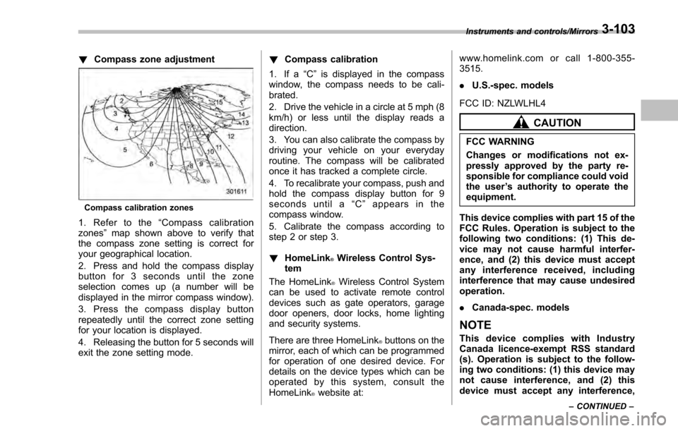
!Compass zone adjustment
Compass calibration zones
1. Refer to the “Compass calibration
zones” map shown above to verify that
the compass zone setting is correct for
your geographical location.
2. Press and hold the compass display
button for 3 seconds until the zone
selection comes up (a number will be
displayed in the mirror compass window).
3. Press the compass display button
repeatedly until the correct zone setting
for your location is displayed.
4. Releasing the button for 5 seconds will
exit the zone setting mode. !
Compass calibration
1. If a “C”is displayed in the compass
window, the compass needs to be cali-
brated.
2. Drive the vehicle in a circle at 5 mph (8
km/h) or less until the display reads a
direction.
3. You can also calibrate the compass by
driving your vehicle on your everyday
routine. The compass will be calibrated
once it has tracked a complete circle.
4. To recalibrate your compass, push and
hold the compass display button for 9
seconds until a “C ” appears in the
compass window.
5. Calibrate the compass according to
step 2 or step 3.
! HomeLink
®Wireless Control Sys-
tem
The HomeLink
®Wireless Control System
can be used to activate remote control
devices such as gate operators, garage
door openers, door locks, home lighting
and security systems.
There are three HomeLink
®buttons on the
mirror, each of which can be programmed
for operation of one desired device. For
details on the device types which can be
operated by this system, consult the
HomeLink
®website at: www.homelink.com or call 1-800-355-
3515.
.
U.S.-spec. models
FCC ID: NZLWLHL4
CAUTION
FCC WARNING
Changes or modifications not ex-
pressly approved by the party re-
sponsible for compliance could void
the user ’s authority to operate the
equipment.
This device complies with part 15 of the
FCC Rules. Operation is subject to the
following two conditions: (1) This de-
vice may not cause harmful interfer-
ence, and (2) this device must accept
any interference received, including
interference that may cause undesired
operation.
. Canada-spec. models
NOTE
This device complies with Industry
Canada licence-exempt RSS standard
(s). Operation is subject to the follow-
ing two conditions: (1) this device may
not cause interference, and (2) this
device must accept any interference,
Instruments and controls/Mirrors
–CONTINUED –3-103
Page 253 of 594
Instruments and controls/Defogger and deicer
&Outside mirrors
! Convex mirror (passenger side)
WARNING
Objects look smaller in a convex
mirror and farther away than when
viewed in a flat mirror. Do not use
the convex mirror to judge the
distance of vehicles behind you
when changing lanes. Use the inside
mirror (or glance backwards) to
determine the actual size and dis-
tance of objects that you view in
convex mirror. !
Remote control mirror switch
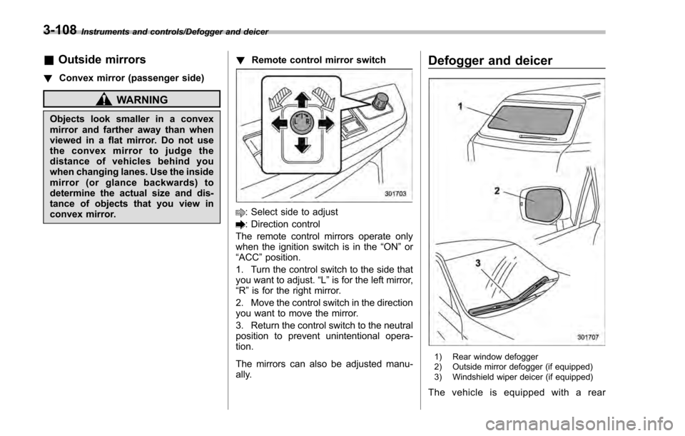
: Select side to adjust
: Direction control
The remote control mirrors operate only
when the ignition switch is in the “ON”or
“ACC ”position.
1. Turn the control switch to the side that
you want to adjust. “L”is for the left mirror,
“R ”is for the right mirror.
2. Move the control switch in the direction
you want to move the mirror.
3. Return the control switch to the neutral
position to prevent unintentional opera-
tion.
The mirrors can also be adjusted manu-
ally.
Defogger and deicer
1) Rear window defogger
2) Outside mirror defogger (if equipped)
3) Windshield wiper deicer (if equipped)
The vehicle is equipped with a rear
3-108
Page 254 of 594
window defogger. Some models are also
equipped with an outside mirror defogger
and/or windshield wiper deicer. The de-
fogger and deicer system is activated only
when the ignition switch is in the“ON”
position.
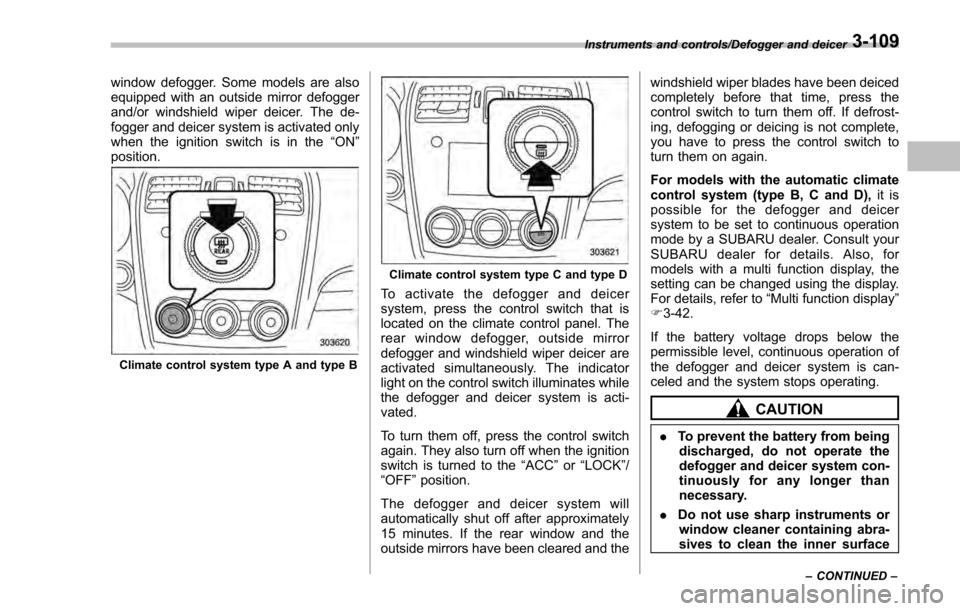
Climate control system type A and type B
Climate control system type C and type D
To activate the defogger and deicer
system, press the control switch that is
located on the climate control panel. The
rear window defogger, outside mirror
defogger and windshield wiper deicer are
activated simultaneously. The indicator
light on the control switch illuminates while
the defogger and deicer system is acti-
vated.
To turn them off, press the control switch
again. They also turn off when the ignition
switch is turned to the “ACC”or “LOCK” /
“OFF ”position.
The defogger and deicer system will
automatically shut off after approximately
15 minutes. If the rear window and the
outside mirrors have been cleared and the windshield wiper blades have been deiced
completely before that time, press the
control switch to turn them off. If defrost-
ing, defogging or deicing is not complete,
you have to press the control switch to
turn them on again.
For models with the automatic climate
control system (type B, C and D),
it is
possible for the defogger and deicer
system to be set to continuous operation
mode by a SUBARU dealer. Consult your
SUBARU dealer for details. Also, for
models with a multi function display, the
setting can be changed using the display.
For details, refer to “Multi function display”
F 3-42.
If the battery voltage drops below the
permissible level, continuous operation of
the defogger and deicer system is can-
celed and the system stops operating.
CAUTION
. To prevent the battery from being
discharged, do not operate the
defogger and deicer system con-
tinuously for any longer than
necessary.
. Do not use sharp instruments or
window cleaner containing abra-
sives to clean the inner surface
Instruments and controls/Defogger and deicer
–CONTINUED –3-109
Page 255 of 594
Instruments and controls/Tilt/telescopic steering wheel
of the rear window. They may
damage the conductors printed
on the window.
NOTE
.Turn on the defogger and deicer
system if the wipers are frozen to the
windshield.
. If the windshield is covered with
snow, remove the snow so that the
windshield wiper deicer works effec-
tively.
. While the defogger and deicer sys-
tem is in the continuous operation
mode, if the vehicle speed remains at
9mph(15km/h)orlowerfor15
minutes, the windshield wiper deicer
automatically stops operating, though
the rear window defogger and outside
mirror defogger maintain continuous
operation in this condition.
. While the defogger and deicer sys-
tem is in the continuous operation
mode, if the battery voltage drops
below the permissible level, continu-
ous operation of the defogger and
deicer system is canceled and the
system stops operating.
Tilt/telescopic steering wheel
WARNING
. Do not adjust the steering wheel
tilt/telescopic position while driv-
ing. This may cause loss of
vehicle control and result in
personal injury.
. If the lever cannot be raised to
the fixed position, adjust the
steering wheel again. It is dan-
gerous to drive without locking
the steering wheel. This may
cause loss of vehicle control
and result in personal injury.
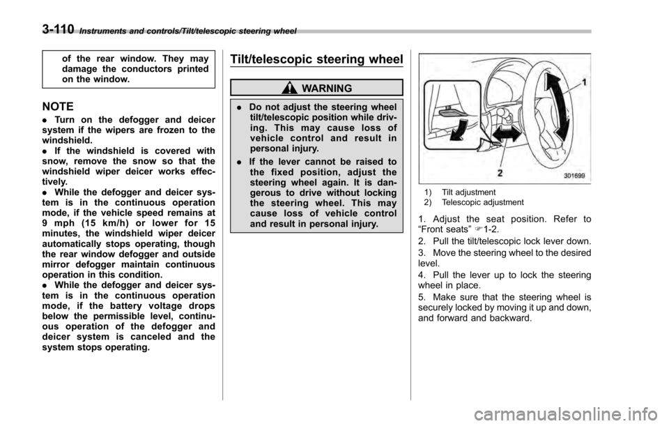
1) Tilt adjustment
2) Telescopic adjustment
1. Adjust the seat position. Refer to
“Front seats ”F 1-2.
2. Pull the tilt/telescopic lock lever down.
3. Move the steering wheel to the desired
level.
4. Pull the lever up to lock the steering
wheel in place.
5. Make sure that the steering wheel is
securely locked by moving it up and down,
and forward and backward.
3-110
Page 260 of 594

Climate control panel
&Type A
1) Temperature control dial (Refer to “Tem-
perature control ”F 4-9.)
2) Air conditioner button (Refer to “Air
conditioner control ”F 4-10.)
3) Fan speed control dial (Refer to “Fan
speed control ”F 4-10.)
4) Air inlet selection button (Refer to “Air
inlet selection ”F 4-10.)
5) Airflow mode selection dial (Refer to “Airflow mode selection ”F 4-8.)
6) Rear window defogger button (Refer to “Defogger and deicer” F3-108.)
Climate control/Climate control panel
–CONTINUED –
4-3