2016 SUBARU IMPREZA tow
[x] Cancel search: towPage 439 of 594
Starting and operating/BSD/RCTA (5–door models —if equipped)
&BSD/RCTA approach indica-
tor light/warning buzzer
When the BSD/RCTA is active, the BSD/
RCTA approach indicator light will operate
to alert the driver when there are vehicles
in the neighboring lanes. When reversing
the vehicle, the BSD/RCTA approach
indicator light and warning buzzer will
operate to alert the driver that a vehicle
is approaching from the left or right side.
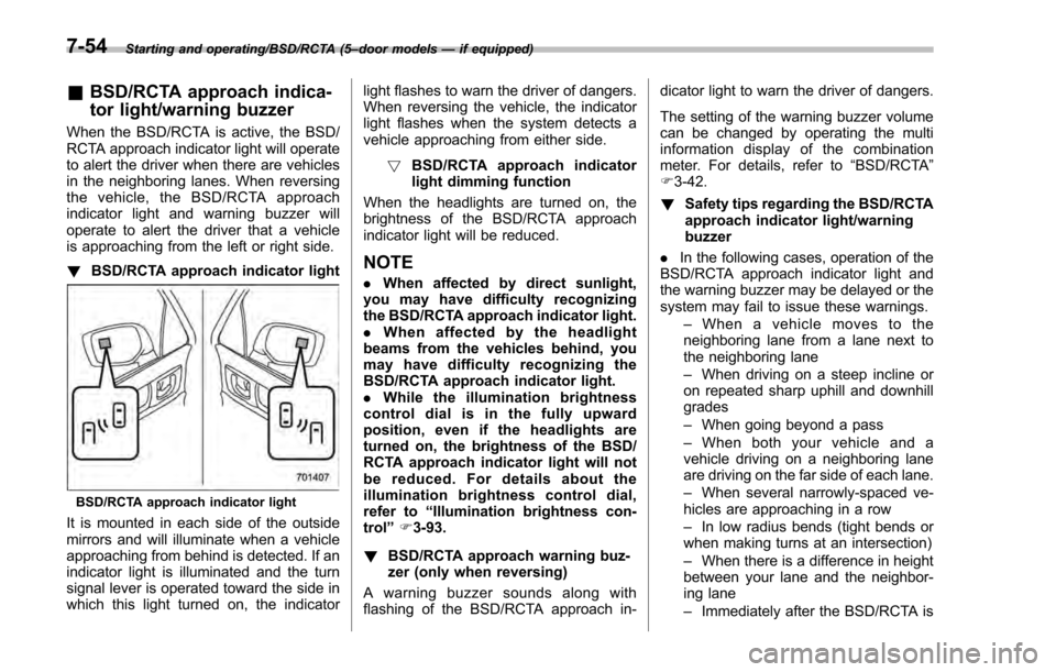
! BSD/RCTA approach indicator light
BSD/RCTA approach indicator light
It is mounted in each side of the outside
mirrors and will illuminate when a vehicle
approaching from behind is detected. If an
indicator light is illuminated and the turn
signal lever is operated toward the side in
which this light turned on, the indicator light flashes to warn the driver of dangers.
When reversing the vehicle, the indicator
light flashes when the system detects a
vehicle approaching from either side.
! BSD/RCTA approach indicator
light dimming function
When the headlights are turned on, the
brightness of the BSD/RCTA approach
indicator light will be reduced.
NOTE
. When affected by direct sunlight,
you may have difficulty recognizing
the BSD/RCTA approach indicator light.
. When affected by the headlight
beams from the vehicles behind, you
may have difficulty recognizing the
BSD/RCTA approach indicator light.
. While the illumination brightness
control dial is in the fully upward
position, even if the headlights are
turned on, the brightness of the BSD/
RCTA approach indicator light will not
be reduced. For details about the
illumination brightness control dial,
refer to “Illumination brightness con-
trol” F3-93.
! BSD/RCTA approach warning buz-
zer (only when reversing)
A warning buzzer sounds along with
flashing of the BSD/RCTA approach in- dicator light to warn the driver of dangers.
The setting of the warning buzzer volume
can be changed by operating the multi
information display of the combination
meter. For details, refer to
“BSD/RCTA”
F 3-42.
! Safety tips regarding the BSD/RCTA
approach indicator light/warning
buzzer
. In the following cases, operation of the
BSD/RCTA approach indicator light and
the warning buzzer may be delayed or the
system may fail to issue these warnings.
–When a vehicle moves to the
neighboring lane from a lane next to
the neighboring lane
– When driving on a steep incline or
on repeated sharp uphill and downhill
grades
– When going beyond a pass
– When both your vehicle and a
vehicle driving on a neighboring lane
are driving on the far side of each lane.
– When several narrowly-spaced ve-
hicles are approaching in a row
– In low radius bends (tight bends or
when making turns at an intersection)
– When there is a difference in height
between your lane and the neighbor-
ing lane
– Immediately after the BSD/RCTA is
7-54
Page 442 of 594
nation meter, and the BSD/RCTA is
deactivated.
Press the switch again to activate the
BSD/RCTA. The BSD/RCTA OFF indica-
tor will disappear.
NOTE
.In the following cases, the system
may not operate properly due to
blocked radar waves. Press the BSD/
RCTA OFF switch to deactivate the
system.
–When towing a trailer
– When a bicycle carrier or other
item is fitted to the rear of the
vehicle
– When using a chassis dynam-
ometer or free roller device, etc.
– When running the engine and
makingthewheelsrotatewhile
lifting up the vehicle
. If the ignition switch is turned to the
“LOCK ”/“OFF ”position, the last known
status of the system is maintained. For
example, if the ignition switch is turned
to the “LOCK ”/“OFF ”position with the
BSD/RCTA deactivated, the BSD/RCTA
will remain deactivated the next time
the ignition switch is turned to the
“ON ”position.
. If the vehicle battery is disconnected
due to situations such as battery terminal or fuse replacement, after the
battery is reconnected, the BSD/RCTA
will be activated.
&
Certification for the BSD/
RCTA
FCC ID: OAYSRR2A
CAUTION
FCC WARNING
Changes or modifications not ex-
pressly approved by the party re-
sponsible for compliance could void
the user ’s authority to operate the
equipment.
This device complies with part 15 of the
FCC Rules. Operation is subject to the
following two conditions: (1) This device
may not cause harmful interference, and
(2) this device must accept any interfer-
ence received, including interference that
may cause undesired operation.
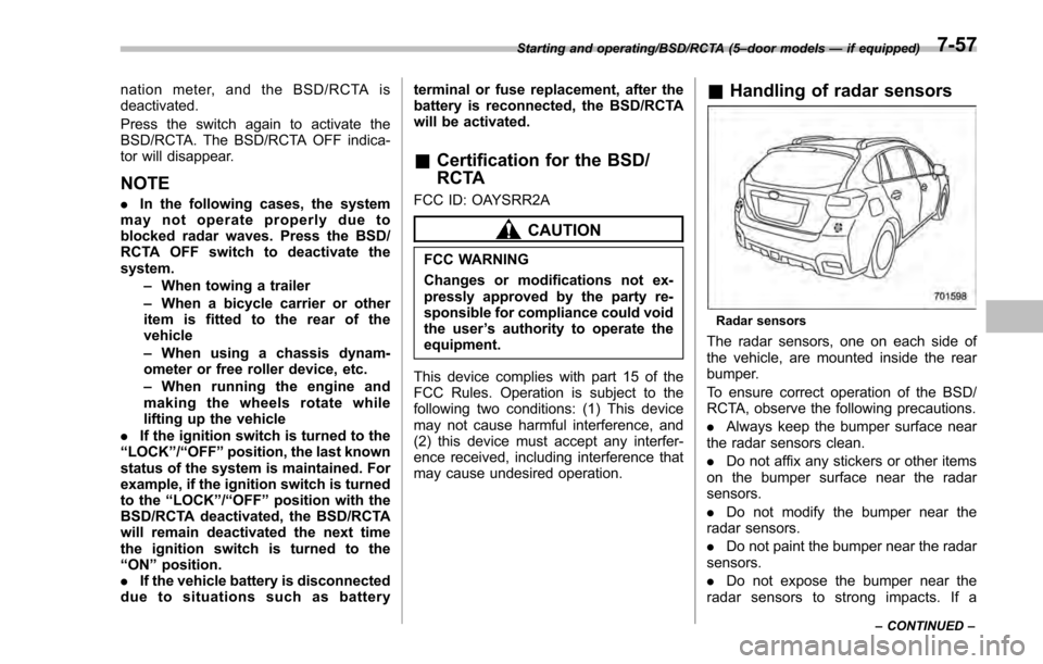
& Handling of radar sensors
Radar sensors
The radar sensors, one on each side of
the vehicle, are mounted inside the rear
bumper.
To ensure correct operation of the BSD/
RCTA, observe the following precautions.
. Always keep the bumper surface near
the radar sensors clean.
. Do not affix any stickers or other items
on the bumper surface near the radar
sensors.
. Do not modify the bumper near the
radar sensors.
. Do not paint the bumper near the radar
sensors.
. Do not expose the bumper near the
radar sensors to strong impacts. If a
Starting and operating/BSD/RCTA (5 –door models —if equipped)
–CONTINUED –7-57
Page 444 of 594
New vehicle break-in driving–the first
1,000 miles (1,600 km) ..................................... 8-2
Fuel economy hints ............................................ 8-2
Engine exhaust gas (carbon monoxide) ............ 8-2
Catalytic converter .............................................. 8-3
Periodic inspections ........................................... 8-4
Driving in foreign countries ............................... 8-4
Driving tips for AWD models .............................. 8-4
Off road driving ................................................... 8-6
Except Crosstrek models. .................................... 8-6
Crosstrek models ................................................ 8-6
Winter driving...................................................... 8-8Operation during cold weather ............................. 8-8
Driving on snowy and icy roads .......................... 8-9
Corrosion protection .......................................... 8-10
Snow tires ......................................................... 8-10
Tire chains ......................................................... 8-11
Rocking the vehicle ............................................ 8-11
Loading your vehicle ......................................... 8-12Vehicle capacity weight ...................................... 8-13
GVWR and GAWR (Gross Vehicle Weight Rating and Gross Axle Weight Rating) ........................ 8-13
Roof rail (if equipped) ........................................ 8-14
Roof molding and crossbar (5-door models —if
equipped) ........................................................ 8-15
Trailer hitch (Crosstrek models —dealer
option) ............................................................. 8-16
Connecting a trailer ........................................... 8-17
If not towing a trailer .......................................... 8-18
Trailer towing (Crosstrek models) .................... 8-18Warranties and maintenance.............................. 8-19
Maximum load limits .......................................... 8-19
Trailer Hitches ................................................... 8-22
Connecting a trailer ........................................... 8-23
Trailer towing tips .............................................. 8-24
Driving tips
8
Page 448 of 594
printed on the tire placard. The
tire placard is located on the
driver’s door pillar.
If all of four tires are not the same
for items (a) to (h), serious me-
chanical damage could occur to
the drive train of your car, and
affect the following.
— Ride
— Handling
— Braking
— Speedometer/Odometer
calibration
— Clearance between the body
and tires
It also may be dangerous and
lead to loss of vehicle control,
and it can lead to an accident.
CAUTION
If you use a temporary spare tire to
replace a flat tire, be sure to use the
original temporary spare tire stored
in the vehicle. Using other sizes may
result in severe mechanical damage
to the drive train of your vehicle.
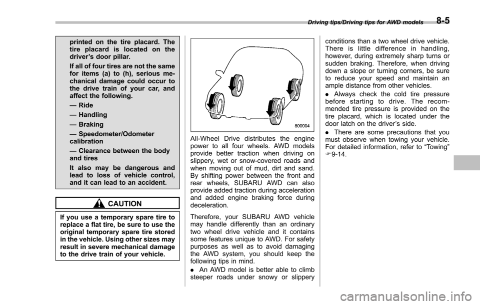
All-Wheel Drive distributes the engine
power to all four wheels. AWD models
provide better traction when driving on
slippery, wet or snow-covered roads and
when moving out of mud, dirt and sand.
By shifting power between the front and
rear wheels, SUBARU AWD can also
provide added traction during acceleration
and added engine braking force during
deceleration.
Therefore, your SUBARU AWD vehicle
may handle differently than an ordinary
two wheel drive vehicle and it contains
some features unique to AWD. For safety
purposes as well as to avoid damaging
the AWD system, you should keep the
following tips in mind.
. An AWD model is better able to climb
steeper roads under snowy or slippery conditions than a two wheel drive vehicle.
There is little difference in handling,
however, during extremely sharp turns or
sudden braking. Therefore, when driving
down a slope or turning corners, be sure
to reduce your speed and maintain an
ample distance from other vehicles.
.
Always check the cold tire pressure
before starting to drive. The recom-
mended tire pressure is provided on the
tire placard, which is located under the
door latch on the driver ’s side.
. There are some precautions that you
must observe when towing your vehicle.
For detailed information, refer to “Towing”
F 9-14.
Driving tips/Driving tips for AWD models8-5
Page 449 of 594
Driving tips/Off road driving
Off road driving
WARNING
.Always maintain a safe driving
speed according to the road and
weather conditions in order to
avoid having an accident on a
sharp turn, during sudden brak-
ing or under other similar condi-
tions.
. Always use the utmost care in
driving –overconfidence be-
cause you are driving an All-
Wheel Drive model could easily
lead to a serious accident.
& Except Crosstrek models
Your AWD vehicle is neither a conven-
tional off-road vehicle nor an all terrain
vehicle. It is a passenger car designed
primarily for on-road use. The AWD
feature gives it some limited off-road
capabilities in situations in which the
driving surface is relatively level, obstruc-
tion-free and otherwise similar to on-road
driving conditions. Operating it under other
than those conditions could subject the
vehicle to excessive stress which might
result in damage not eligible for repair under warranty.
If you do take your SUBARU off road, you
should review the common sense precau-
tions in the next section (applicable to the
Crosstrek models) for general guidance.
But please keep in mind that your vehi-
cle
’s off-road capabilities are more limited
than those of the Crosstrek models.
Never attempt to drive through pools and
puddles, or roads flooded with water.
Water entering the engine air intake or
the exhaust pipe or water splashing onto
electrical parts may damage your vehicle
and may cause it to stall.
& Crosstrek models
CAUTION
Frequent driving of an AWD model
under hard-driving conditions such
as rough roads or off roads will
necessitate more frequent replace-
ment of the following items than that
specified in the maintenance sche-
dule described in the “Warranty and
Maintenance Booklet ”.
. Engine oil
. Brake fluid
. Manual transmission oil (MT
models) .
Continuously variable transmis-
sion fluid (CVT models)
. Front differential gear oil (CVT
models)
Remember that damage done to
your SUBARU while operating it
off-road and not using common
sense precautions such as those
listed here is not eligible for war-
ranty coverage.
Because of the AWD feature and higher
ground clearance, you can drive your
SUBARU on ordinary roads or off-road.
But please keep in mind that an AWD
SUBARU is a passenger car and is
neither a conventional off-road vehicle
nor an all-terrain vehicle. If you do take
your SUBARU off-road, certain common
sense precautions such as those in the
following list should be taken.
! Before driving
. Make certain that you and all of your
passengers are wearing seatbelts.
. Carry some emergency equipment,
such as a towing rope or chain, a shovel,
wheel blocks, first aid kit and cell phone or
citizens band radio.
. Secure all cargo carried inside the
vehicle and make certain that it is not
piled higher than the seatbacks. During
8-6
Page 459 of 594
Driving tips/Trailer hitch (Crosstrek models—dealer option)
! Removal and installation of the
crossbars
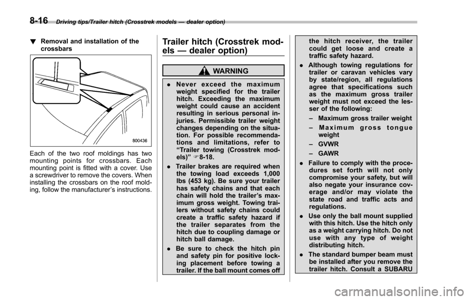
Each of the two roof moldings has two
mounting points for crossbars. Each
mounting point is fitted with a cover. Use
a screwdriver to remove the covers. When
installing the crossbars on the roof mold-
ing, follow the manufacturer ’s instructions.
Trailer hitch (Crosstrek mod-
els —dealer option)
WARNING
. Never exceed the maximum
weight specified for the trailer
hitch. Exceeding the maximum
weight could cause an accident
resulting in serious personal in-
juries. Permissible trailer weight
changes depending on the situa-
tion. For possible recommenda-
tions and limitations, refer to
“Trailer towing (Crosstrek mod-
els) ”F 8-18.
. Trailer brakes are required when
the towing load exceeds 1,000
lbs (453 kg). Be sure your trailer
has safety chains and that each
chain will hold the trailer ’s max-
imum gross weight. Towing trai-
lers without safety chains could
create a traffic safety hazard if
the trailer separates from the
hitch due to coupling damage or
hitch ball damage.
. Be sure to check the hitch pin
and safety pin for positive lock-
ing placement before towing a
trailer. If the ball mount comes off the hitch receiver, the trailer
could get loose and create a
traffic safety hazard.
. Although towing regulations for
trailer or caravan vehicles vary
by state/region, all regulations
agree that specifications such
as the maximum gross trailer
weight must not exceed the les-
ser of the following:
– Maximum gross trailer weight
– Maximum gross tongue
weight
– GVWR
– GAWR
. Failure to comply with the proce-
dures set forth will not only
compromise your safety, but will
also negate your insurance cov-
erageand/ormayviolatethe
state road and traffic acts and
regulations.
. Use only the ball mount supplied
with this hitch. Use the hitch only
as a weight carrying hitch. Do not
use with any type of weight
distributing hitch.
. The standard bumper beam must
be installed after you remove the
trailer hitch. Consult a SUBARU
8-16
Page 460 of 594
dealer for purchase of a standard
bumper beam if you do not have
the original.
. Safety performance is decreased
and there is increased risk of
injury to passengers in the case
of an accident if the trailer hitch
or a standard bumper beam is
not installed. One of them must
always be installed on the vehi-
cle.
. If a trailer hitch is installed, it is
not possible to install the rear
towing hook.
The maximum gross trailer weight and
maximum gross tongue weight are indi-
cated in the following table.
Maximum
gross trailer
weight Maximum
gross ton-
gue weight
Crosstrek models 1,500 lbs
(680 kg) 200 lbs
(90 kg)
When towing a trailer, refer to “Trailer
towing (Crosstrek models) ”F 8-18.
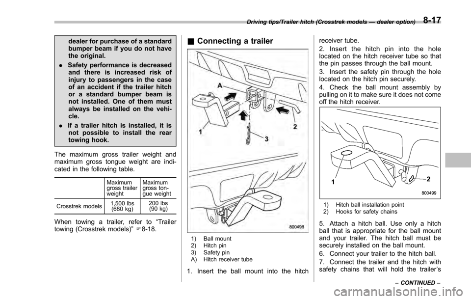
& Connecting a trailer
1) Ball mount
2) Hitch pin
3) Safety pin
A) Hitch receiver tube
1. Insert the ball mount into the hitch receiver tube.
2. Insert the hitch pin into the hole
located on the hitch receiver tube so that
the pin passes through the ball mount.
3. Insert the safety pin through the hole
located on the hitch pin securely.
4. Check the ball mount assembly by
pulling on it to make sure it does not come
off the hitch receiver.
1) Hitch ball installation point
2) Hooks for safety chains
5. Attach a hitch ball. Use only a hitch
ball that is appropriate for the ball mount
and your trailer. The hitch ball must be
securely installed on the ball mount.
6. Connect your trailer to the hitch ball.
7. Connect the trailer and the hitch with
safety chains that will hold the trailer
’s
Driving tips/Trailer hitch (Crosstrek models —dealer option)
–CONTINUED –8-17
Page 461 of 594
Driving tips/Trailer towing (Crosstrek models)
maximum gross weight. The chains
should cross under the trailer tongue to
prevent the tongue from dropping onto the
ground in case it should disconnect from
the hitch ball. Allow sufficient slack in the
chains taking tight turn situations into
account; however, be careful not to let
them drag on the ground.
WARNING
Do not connect safety chains to any
part of the vehicle other than the
safety chain hooks.
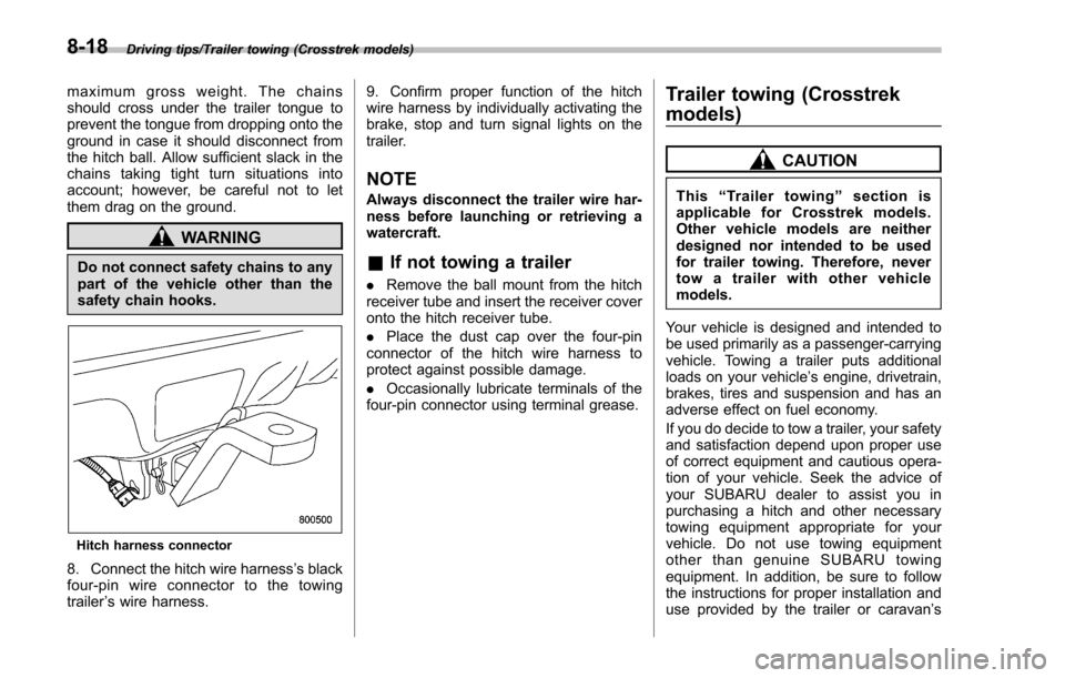
Hitch harness connector
8. Connect the hitch wire harness’s black
four-pin wire connector to the towing
trailer ’s wire harness. 9. Confirm proper function of the hitch
wire harness by individually activating the
brake, stop and turn signal lights on the
trailer.
NOTE
Always disconnect the trailer wire har-
ness before launching or retrieving a
watercraft.
&
If not towing a trailer
. Remove the ball mount from the hitch
receiver tube and insert the receiver cover
onto the hitch receiver tube.
. Place the dust cap over the four-pin
connector of the hitch wire harness to
protect against possible damage.
. Occasionally lubricate terminals of the
four-pin connector using terminal grease.
Trailer towing (Crosstrek
models)
CAUTION
This “Trailer towing ”section is
applicable for Crosstrek models.
Other vehicle models are neither
designed nor intended to be used
for trailer towing. Therefore, never
tow a trailer with other vehicle
models.
Your vehicle is designed and intended to
be used primarily as a passenger-carrying
vehicle. Towing a trailer puts additional
loads on your vehicle’ s engine, drivetrain,
brakes, tires and suspension and has an
adverse effect on fuel economy.
If you do decide to tow a trailer, your safety
and satisfaction depend upon proper use
of correct equipment and cautious opera-
tion of your vehicle. Seek the advice of
your SUBARU dealer to assist you in
purchasing a hitch and other necessary
towing equipment appropriate for your
vehicle. Do not use towing equipment
other than genuine SUBARU towing
equipment. In addition, be sure to follow
the instructions for proper installation and
use provided by the trailer or caravan ’s
8-18