2016 SUBARU IMPREZA tow
[x] Cancel search: towPage 366 of 594

Interior lights....................................................... 6-2Dome light.......................................................... 6-2
Cargo area light (5-door models) ......................... 6-2
Map lights ........................................................... 6-3
OFF delay timer .................................................. 6-3
Sun visors........................................................... 6-4Sun visor extension plate (models with the
EyeSight system) .............................................. 6-4
Vanity mirror ....................................................... 6-5
Storage compartment ......................................... 6-5Glove box........................................................... 6-6
Center console .................................................... 6-6
Cup holders......................................................... 6-7
Bottle holders ...................................................... 6-7
Accessory power outlets .................................... 6-8
Use with a cigarette lighter (dealer option) ........... 6-9
Ashtray (dealer option)...................................... 6-10 Floor mat (if equipped)
...................................... 6-11
Coat hook ........................................................... 6-11
Shopping bag hook (5-door) ............................. 6-12
Cargo area cover (5-door –if equipped) .......... 6-12
Using the cover ................................................. 6-12
To remove the cover housing ... .......................... 6-13
Stowage of the cargo area cover ........................ 6-13
To install the cover housing ............................... 6-14
Cargo tie-down hooks (5-door –if
equipped) ........................................................ 6-14
Under-floor storage compartment (if equipped) ........................................................ 6-15
Rear view camera .............................................. 6-15
How to use the rear view camera ....................... 6-17
Viewing range on the screen .............................. 6-17
Help line ............................................................ 6-18
Interior equipment
6
Page 369 of 594

Interior equipment/Sun visors
the lights remain on (OFF delay timer) can
be changed by a SUBARU dealer. Con-
tact your SUBARU dealer for details. For
models with multi function display, the
setting can be changed by operating the
multi function display. For details, refer to
“Interior light off delay timer setting”F 3-
82.Sun visors
To block out glare, swing down the visors.
To use the sun visor at a side window,
swing it down and move it sideways.
& Sun visor extension plate
(models with the EyeSight
system)
With the sun visor positioned over the side
window, you can use the sun visor
extension plate to prevent glare through
the gap between the sun visor and center
pillar. To use the extension plate, pull it
toward the rear of the vehicle. When you
have finished using it, stow it by pushing it
toward the front of the vehicle.
6-4
Page 378 of 594
WARNING
Do not place anything on the ex-
tended cover. Putting excessive
weight on the extended cover can
break it and an object on the cover
could tumble forward in the event of
a sudden stop or collision. This
could cause serious injury.
CAUTION
Be careful not to scratch the rear
gate stays while extending and
rewinding the cover.
Scratches on the stays could cause
leakage of gas from the stays, which
may result in their inability to hold
the rear gate open.
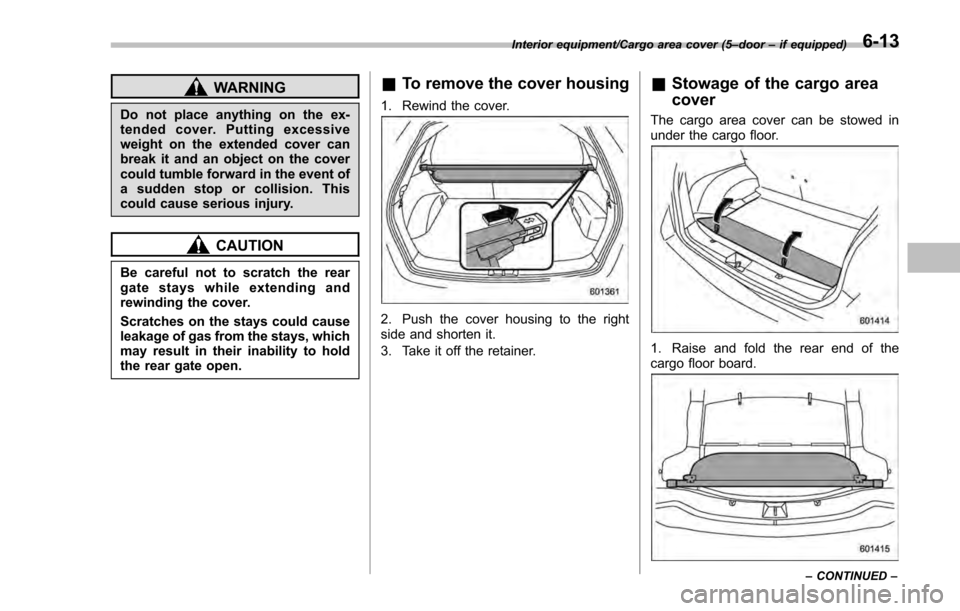
&To remove the cover housing
1. Rewind the cover.
2. Push the cover housing to the right
side and shorten it.
3. Take it off the retainer.
&Stowage of the cargo area
cover
The cargo area cover can be stowed in
under the cargo floor.
1. Raise and fold the rear end of the
cargo floor board.
Interior equipment/Cargo area cover (5– door–if equipped)
–CONTINUED –6-13
Page 379 of 594
Interior equipment/Cargo tie–down hooks (5 –door –if equipped)
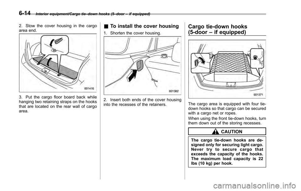
2. Stow the cover housing in the cargo
area end.
3. Put the cargo floor board back while
hanging two retaining straps on the hooks
that are located on the rear wall of cargo
area.
& To install the cover housing
1. Shorten the cover housing.
2. Insert both ends of the cover housing
into the recesses of the retainers.
Cargo tie-down hooks
(5-door –if equipped)
The cargo area is equipped with four tie-
down hooks so that cargo can be secured
with a cargo net or ropes.
When using the front tie-down hooks, turn
them down out of the storing recesses.
CAUTION
The cargo tie-down hooks are de-
signed only for securing light cargo.
Never try to secure cargo that
exceeds the capacity of the hooks.
The maximum load capacity is 22
lbs (10 kg) per hook.
6-14
Page 409 of 594
Starting and operating/Continuously variable transmission
mission.
. When parking the vehicle, first
securely apply the parking brake
and then place the select lever in
the “P”position. Do not park for
a long time with the select lever
in any other position as doing so
could result in a dead battery.
& Continuously variable trans-
mission features
The continuously variable transmission is
electronically controlled and provides an
infinite number of forward speeds and 1
reverse speed. For some models, it also
has a manual mode or an “L”position.
NOTE
. When the engine coolant tempera-
ture is still low, the transmission will
upshift or downshift at higher engine
speeds than when the coolant tempera-
ture is sufficiently high in order to
shorten the warm-up time and improve
driveability. The gearshift timing will
automatically shift to the normal timing
after the engine has warmed up.
. Immediately after transmission fluid
is replaced, you may feel that the
transmission operation is somewhat
unusual. This results from invalidation of data which the on-board computer
has collected and stored in memory to
allow the transmission to shift at the
most appropriate times for the current
condition of your vehicle. Optimized
shifting will be restored as the vehicle
continues to be driven for a while.
.
When driving a CVT model under
continuous heavy load conditions such
as when towing a camper or climbing a
long, steep hill, the engine speed or the
vehicle speed may automatically be
reduced. This is not a malfunction. This
phenomenon results from the engine
control function maintaining the cool-
ing performance of the vehicle. The
engine and vehicle speed will return to
a normal speed when the engine is able
to maintain the optimum cooling per-
formance after the heavy load de-
creases. Driving under a heavy load
must be performed with extreme care.
Do not try to pass a vehicle in front
when driving on an uphill slope while
towing. .
The continuously variable transmis-
sion is a chain type system that
provides superior transmission effi-
ciency for maximum fuel economy. At
times, depending on varying driving
conditions, a chain operating sound
may be heard that is characteristic of
this type of system.
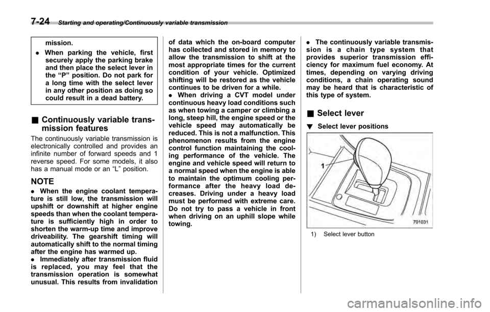
& Select lever
! Select lever positions
1) Select lever button
7-24
Page 419 of 594
Starting and operating/Vehicle Dynamics Control system
system warning light and ABS warning
light illuminate simultaneously.
The EBD system may be malfunctioning if
the brake system warning light and ABS
warning light illuminate simultaneously
during driving.
Even if the EBD system malfunctions, the
conventional braking system will still func-
tion. However, the rear wheels will be
more prone to locking when the brakes
are applied harder than usual and the
vehicle’s motion may therefore become
somewhat harder to control.
If the brake system warning light and ABS
warning light illuminate simultaneously,
take the following steps.
1. Stop the vehicle in the nearest safe,
flat location.
2. Apply the parking brake and turn off
the engine.
3. Restart the engine.
4. Release the parking brake.
Even if both warning lights turn off:
The EBD system may be malfunctioning.
Drive carefully to the nearest SUBARU
dealer and have the system inspected.
If both warning lights illuminate again
and remain illuminated after restarting
the engine:
1. Turn off the engine again. 2. Apply the parking brake.
3. Check the brake fluid level. For details
about checking the brake fluid level, refer
to
“Checking the fluid level ”F 11-16.
. If the brake fluid level is not below the
“MIN ”mark, the EBD system may be
malfunctioning. Drive carefully to the
nearest SUBARU dealer and have the
system inspected.
. If the brake fluid level is below the
“MIN ”mark, DO NOT drive the vehicle.
Instead, have the vehicle towed to the
nearest SUBARU dealer for repair.
WARNING
. Driving with the brake system
warning light illuminated is dan-
gerous. This indicates your brake
system may not be working
properly. If the light remains
illuminated, have the brakes in-
spected by a SUBARU dealer
immediately.
. If at all in doubt about whether
the brakes are operating prop-
erly, do not drive the vehicle.
Have your vehicle towed to the
nearest SUBARU dealer for re-
pair.
Vehicle Dynamics Control
system
& Safety precautions
WARNING
Always use the utmost care in
driving –overconfidence because
you are driving a vehicle with the
Vehicle Dynamics Control system
could easily lead to a serious acci-
dent.
CAUTION
. Even if your vehicle is equipped
with Vehicle Dynamics Control
system, winter tires should be
used when driving on snow-cov-
ered or icy roads; in addition,
vehicle speed should be reduced
considerably. Simply having a
Vehicle Dynamics Control sys-
tem does not guarantee that the
vehicle will be able to avoid
accidents in any situation.
. Activation of the Vehicle Dy-
namics Control system is an
indication that the road being
travelled on has a slippery sur-
7-34
Page 421 of 594
Starting and operating/Vehicle Dynamics Control system
–The brake pedal seems to jolt
when driving off after starting the
engine.
. In the circumstances shown in the
following list, the vehicle may be less
stable than it feels to the driver. The
Vehicle Dynamics Control System may
therefore operate. Such operation does
not indicate a system malfunction.
–on gravel-covered or rutted
roads
– on unfinished roads
– when the vehicle is towing a
trailer (trailer towing permitted with
Crosstrek models only)
– when the vehicle is fitted with
snow tires or winter tires
. Activation of the Vehicle Dynamics
Control system will cause operation of
the steering wheel to feel slightly
different compared to that for normal
conditions.
. It is always important to reduce
speed when approaching a corner,
even if your vehicle is equipped with
the Vehicle Dynamics Control system.
. Always turn off the engine before
replacing a tire. Failure to do so may
render the Vehicle Dynamics Control
system unable to operate correctly.& Vehicle Dynamics Control
system monitor
Refer to “Vehicle Dynamics Control warn-
ing light/Vehicle Dynamics Control opera-
tion indicator light ”F 3-24 and “Vehicle
Dynamics Control OFF indicator light ”F 3-
25.
& Vehicle Dynamics Control
OFF switch
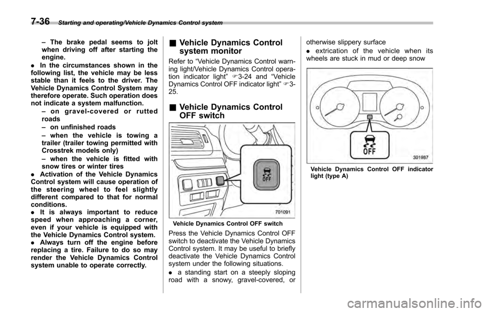
Vehicle Dynamics Control OFF switch
Press the Vehicle Dynamics Control OFF
switch to deactivate the Vehicle Dynamics
Control system. It may be useful to briefly
deactivate the Vehicle Dynamics Control
system under the following situations.
. a standing start on a steeply sloping
road with a snowy, gravel-covered, or otherwise slippery surface
.
extrication of the vehicle when its
wheels are stuck in mud or deep snow
Vehicle Dynamics Control OFF indicator
light (type A)
7-36
Page 430 of 594
Cruise control (if equipped)
NOTE
For models with EyeSight system:
Refer to the Owner’s Manual supple-
ment for the EyeSight system.
Cruise control enables you to maintain a
constant vehicle speed without holding
your foot on the accelerator pedal and it is
operative when the vehicle speed is 25
mph (40 km/h) or more.
WARNING
Do not use the cruise control under
any of the following conditions.
These may cause loss of vehicle
control.
. driving up or down a steep grade
. driving on slippery or winding
roads
. driving in heavy traffic
. towing a trailer
NOTE
Make sure the cruise control system is
turned off when the cruise control is
not in use to avoid unintentionally
setting of the cruise control.
&To set cruise control
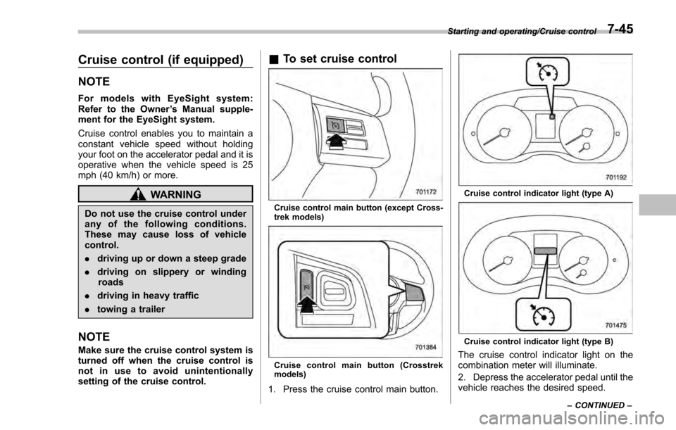
Cruise control main button (except Cross-
trek models)
Cruise control main button (Crosstrek
models)
1. Press the cruise control main button.
Cruise control indicator light (type A)
Cruise control indicator light (type B)
The cruise control indicator light on the
combination meter will illuminate.
2. Depress the accelerator pedal until the
vehicle reaches the desired speed.
Starting and operating/Cruise control
–CONTINUED –7-45