Page 203 of 594
Instruments and controls/Multi function display
4. Select a number by operating the“”
or “”switch. Then push thebutton.
When “12 h”is selected, the clock will be
set to a 12-hour display. When “24 h”is
selected, the clock will be set to a 24-hour
display.
5. After entering the date and time, select
“Set ”by operating the “”switch and
confirm the setting by pushing the
button.
6. The system will notify you that the
setting is complete.
! Birthday setting
1. Perform the preparation steps accord-
ing to “Preparation for date setting ”F 3-
57.
2. Operate the “”or “”switch to
select the “Birthday ”item. Then push the
button.
3. Select an entry in the list to set by
operating the “”or “”switch. Then
push thebutton.
3-58
Page 216 of 594
switch, and confirm the setting by pushing
thebutton.
6. The system will notify you that the
setting is complete.
!Clock/calendar screen setting
1. Perform the preparation steps accord-
ing to “Preparation for screen settings ”
F 3-66.
2. Operate the “”or “”switch to
select the “Clock”item. Then push the
button.
3. Push thebutton once more.
4. Select “Analog Clock ”,“Digital Clock ”,
“Calendar ”or “Off ”by operating the “”
switch. Then push thebutton.
5. Select “Set ”by operating the “”
switch, and confirm the setting by pushing
the
button.
Instruments and controls/Multi function display
–CONTINUED –3-71
Page 266 of 594

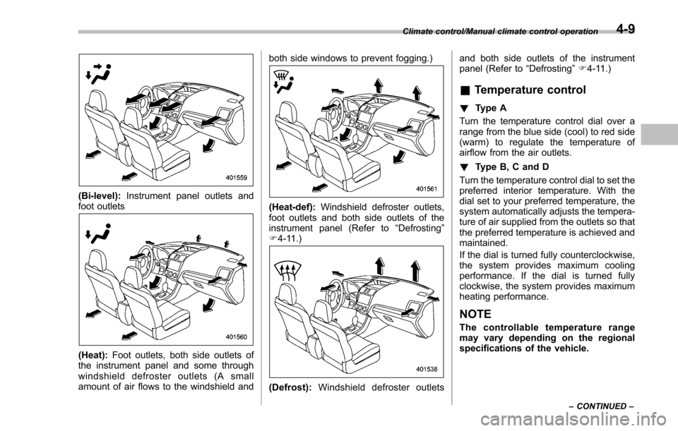
(Bi-level):Instrument panel outlets and
foot outlets
(Heat): Foot outlets, both side outlets of
the instrument panel and some through
windshield defroster outlets (A small
amount of air flows to the windshield and both side windows to prevent fogging.)
(Heat-def):
Windshield defroster outlets,
foot outlets and both side outlets of the
instrument panel (Refer to “Defrosting ”
F 4-11.)
(Defrost): Windshield defroster outlets and both side outlets of the instrument
panel (Refer to
“Defrosting”F 4-11.)
& Temperature control
! Type A
Turn the temperature control dial over a
range from the blue side (cool) to red side
(warm) to regulate the temperature of
airflow from the air outlets.
! Type B, C and D
Turn the temperature control dial to set the
preferred interior temperature. With the
dial set to your preferred temperature, the
system automatically adjusts the tempera-
ture of air supplied from the outlets so that
the preferred temperature is achieved and
maintained.
If the dial is turned fully counterclockwise,
the system provides maximum cooling
performance. If the dial is turned fully
clockwise, the system provides maximum
heating performance.
NOTE
The controllable temperature range
may vary depending on the regional
specifications of the vehicle.
Climate control/Manual climate control operation
–CONTINUED –4-9
Page 322 of 594

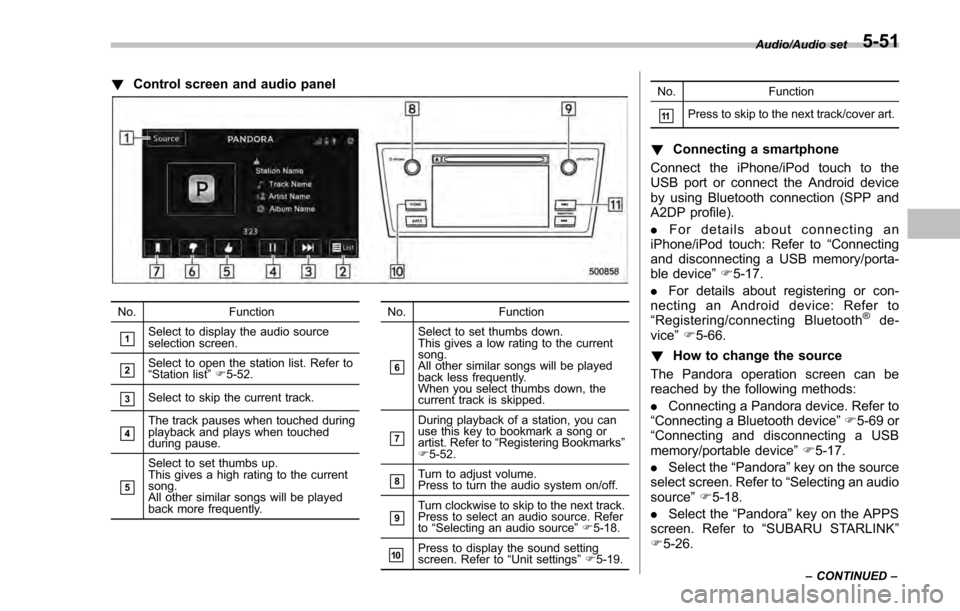
!Control screen and audio panel
No. Function
&1Select to display the audio source
selection screen.
&2Select to open the station list. Refer to
“Station list ”F 5-52.
&3Select to skip the current track.
&4The track pauses when touched during
playback and plays when touched
during pause.
&5
Select to set thumbs up.
This gives a high rating to the current
song.
All other similar songs will be played
back more frequently. No. Function
&6
Select to set thumbs down.
This gives a low rating to the current
song.
All other similar songs will be played
back less frequently.
When you select thumbs down, the
current track is skipped.
&7
During playback of a station, you can
use this key to bookmark a song or
artist. Refer to
“Registering Bookmarks ”
F 5-52.
&8Turn to adjust volume.
Press to turn the audio system on/off.
&9Turn clockwise to skip to the next track.
Press to select an audio source. Refer
to “Selecting an audio source ”F 5-18.
&10Press to display the sound setting
screen. Refer to “Unit settings ”F 5-19. No. Function
&11Press to skip to the next track/cover art.
!
Connecting a smartphone
Connect the iPhone/iPod touch to the
USB port or connect the Android device
by using Bluetooth connection (SPP and
A2DP profile).
. For details about connecting an
iPhone/iPod touch: Refer to “Connecting
and disconnecting a USB memory/porta-
ble device ”F 5-17.
. For details about registering or con-
necting an Android device: Refer to
“ Registering/connecting Bluetooth
®de-
vice” F5-66.
! How to change the source
The Pandora operation screen can be
reached by the following methods:
. Connecting a Pandora device. Refer to
“ Connecting a Bluetooth device ”F 5-69 or
“ Connecting and disconnecting a USB
memory/portable device ”F 5-17.
. Select the “Pandora”key on the source
select screen. Refer to “Selecting an audio
source” F5-18.
. Select the “Pandora”key on the APPS
screen. Refer to “SUBARU STARLINK ”
F 5-26.
Audio/Audio set
–CONTINUED –5-51
Page 391 of 594

Starting and operating/Fuel
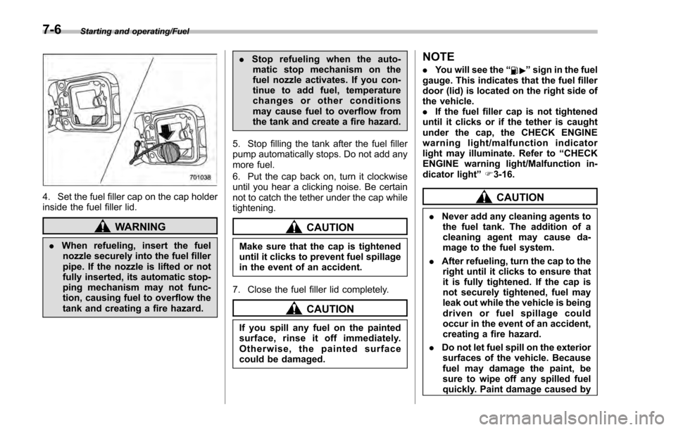
4. Set the fuel filler cap on the cap holder
inside the fuel filler lid.
WARNING
.When refueling, insert the fuel
nozzle securely into the fuel filler
pipe. If the nozzle is lifted or not
fully inserted, its automatic stop-
ping mechanism may not func-
tion, causing fuel to overflow the
tank and creating a fire hazard. .
Stop refueling when the auto-
matic stop mechanism on the
fuel nozzle activates. If you con-
tinue to add fuel, temperature
changes or other conditions
may cause fuel to overflow from
the tank and create a fire hazard.
5. Stop filling the tank after the fuel filler
pump automatically stops. Do not add any
more fuel.
6. Put the cap back on, turn it clockwise
until you hear a clicking noise. Be certain
not to catch the tether under the cap while
tightening.
CAUTION
Make sure that the cap is tightened
until it clicks to prevent fuel spillage
in the event of an accident.
7. Close the fuel filler lid completely.
CAUTION
If you spill any fuel on the painted
surface, rinse it off immediately.
Otherwise, the painted surface
could be damaged.
NOTE
. You will see the “”sign in the fuel
gauge. This indicates that the fuel filler
door (lid) is located on the right side of
the vehicle.
. If the fuel filler cap is not tightened
until it clicks or if the tether is caught
under the cap, the CHECK ENGINE
warning light/malfunction indicator
light may illuminate. Refer to “CHECK
ENGINE warning light/Malfunction in-
dicator light ”F 3-16.
CAUTION
. Never add any cleaning agents to
the fuel tank. The addition of a
cleaning agent may cause da-
mage to the fuel system.
. After refueling, turn the cap to the
right until it clicks to ensure that
it is fully tightened. If the cap is
not securely tightened, fuel may
leak out while the vehicle is being
driven or fuel spillage could
occur in the event of an accident,
creating a fire hazard.
. Do not let fuel spill on the exterior
surfaces of the vehicle. Because
fuel may damage the paint, be
sure to wipe off any spilled fuel
quickly. Paint damage caused by
7-6
Page 533 of 594

Maintenance and service/Replacing bulbs
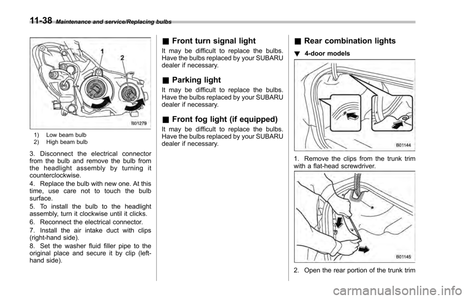
1) Low beam bulb
2) High beam bulb
3. Disconnect the electrical connector
from the bulb and remove the bulb from
the headlight assembly by turning it
counterclockwise.
4. Replace the bulb with new one. At this
time, use care not to touch the bulb
surface.
5. To install the bulb to the headlight
assembly, turn it clockwise until it clicks.
6. Reconnect the electrical connector.
7. Install the air intake duct with clips
(right-hand side).
8. Set the washer fluid filler pipe to the
original place and secure it by clip (left-
hand side).
&Front turn signal light
It may be difficult to replace the bulbs.
Have the bulbs replaced by your SUBARU
dealer if necessary.
&Parking light
It may be difficult to replace the bulbs.
Have the bulbs replaced by your SUBARU
dealer if necessary.
&Front fog light (if equipped)
It may be difficult to replace the bulbs.
Have the bulbs replaced by your SUBARU
dealer if necessary.
&Rear combination lights
! 4-door models
1. Remove the clips from the trunk trim
with a flat-head screwdriver.
2. Open the rear portion of the trunk trim
11-38
Page 534 of 594
panel as illustrated.
NOTE
Make sure that the“*”part of the trunk
trim in the illustration does not contact
the trunk lid stay. If the “
*”part is bent,
the trunk trim may be torn.
1) Stop light/Tail and rear side marker light
2) Rear turn signal light
3) Backup light
3. Remove the bulb socket from the rear
combination light assembly by turning it
counterclockwise.
4. Pull the bulb out of the bulb socket and
replace it with a new one.
5. Set the bulb socket into the rear
combination light assembly and turn it
clockwise until it locks. 6. Secure the rear trunk trim panel with
the clips.
!
5-door models
1. Using a Phillips screwdriver, remove
the upper and lower screws that secure
the rear combination light assembly.
2. Slide the rear combination light as-
sembly rearward and remove it from the
vehicle.
Maintenance and service/Replacing bulbs
–CONTINUED –11-39
Page 535 of 594
Maintenance and service/Replacing bulbs
1) Rear side marker light
2) Rear turn signal light
3) Backup light
4) Stop light/Tail light
3. Remove the bulb socket from the rear
combination light assembly by turning it
counterclockwise.
4. Pull the bulb out of the bulb socket and
replace it with a new one.
5. Set the bulb socket into the rear
combination light assembly and turn it
clockwise until it locks.
1) Guide pins
2) Catch
3) Clip
6. Put the rear combination light assem-
bly into place while aligning the 2 guide
pins and a catch with the guide holes and
a clip on the vehicle.
7. Tighten the upper and lower screws.
11-40