2016 SUBARU IMPREZA low beam
[x] Cancel search: low beamPage 239 of 594

Instruments and controls/Headlight beam leveler
Headlight beam leveler (if
equipped)
&Automatic headlight beam
leveler (models with HID
headlights)
The HID headlights generate more light
than conventional halogen headlights.
Therefore a driver of an oncoming vehicle
may experience too much glare if your
headlight beam height adjustment is high
when the vehicle is carrying a heavy load.
The automatic headlight beam leveler
adjusts the headlight beam height auto-
matically and optimally according to the
load being carried by the vehicle.
Fog light switch (if equipped)
1) Headlight switch
2) Fog light switch
The front fog lights will turn on when the
fog light switch is placed in the “”
position while the headlights are in the
following condition.
. while the headlight switch is in the “
”
position
. for models with the auto on/off head-
lights, while the headlight switch is in the
“AUTO ”position and the low beam head-
lights turn on automatically
To turn off the front fog lights, turn the
switch back down to the “
”position.
Indicator light (type A)
Indicator light (type B)
The indicator light on the combination
meter will illuminate when the front fog
lights are illuminated.
3-94
Page 240 of 594
&Steering responsive fog
lights system (models with
EyeSight system)
The steering responsive fog lights system
automatically turns the front fog light on
and off based on the steering angle and
vehicle speed when entering a curve or
driving on curved roads. The system is
intended to help prevent accidents by
enabling better visibility of curves ahead
and early recognition of any disabled
vehicles or other obstacles.
The front fog light on the inside of a curve
will turn on if all of the following conditions
are met.
. The light control switch is in the “
”
position
. The light control switch is in the
“AUTO ”position and the low beam head-
lights turn on automatically
. The fog light switch is in the “
”
position
. The low beam mode is selected
. The select lever is in a position other
than the “R”position
. The steering response fog lights sys-
tem has not been deactivated
. The operating conditions such as the
steering angle and vehicle speed are met
The front fog lights on both sides will turn on as usual if all of the following conditions
are met.
.
The light control switch is in either of
the following conditions.
–in the “
”position
– in the “AUTO ”position and the low
beam headlights turn on automatically
. The fog light switch is in the “
”
position
. The low beam mode is selected !
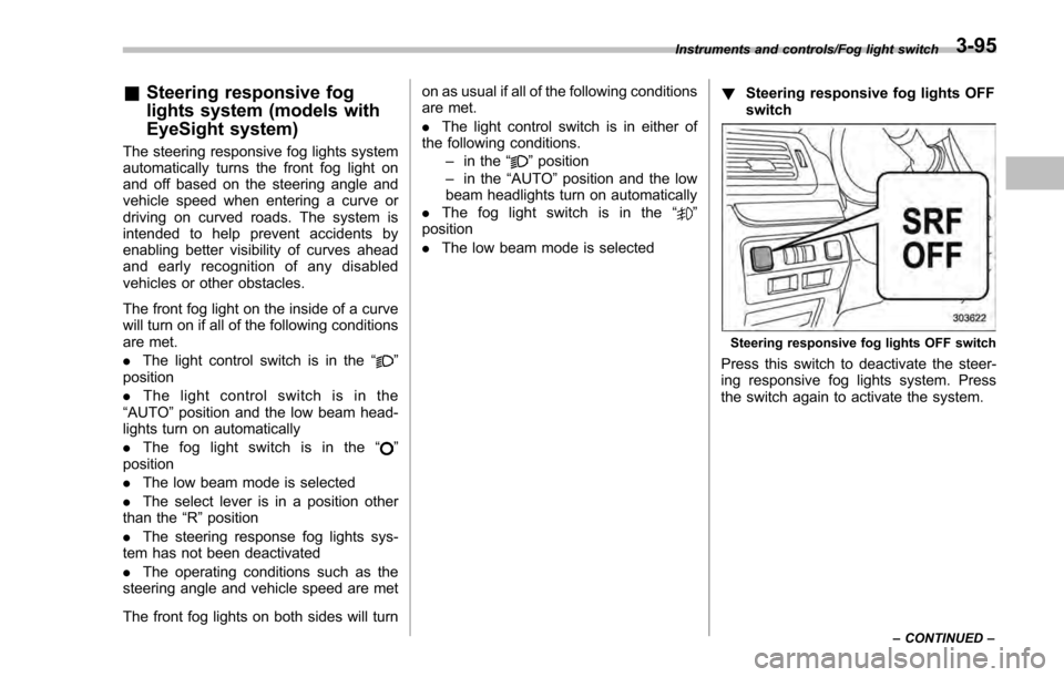
Steering responsive fog lights OFF
switch
Steering responsive fog lights OFF switch
Press this switch to deactivate the steer-
ing responsive fog lights system. Press
the switch again to activate the system.
Instruments and controls/Fog light switch
–CONTINUED –3-95
Page 279 of 594
Audio/Audio set
!CD player and disc
. This CD player is intended for use with
4.7 in. (12 cm) discs only.
. Extremely high temperatures can keep
the CD player from working. On hot days,
use the air conditioning system to cool the
inside of the vehicle before using the
player.
. Bumpy roads or other vibrations may
make the CD player skip.
. If moisture gets into the CD player, the
discs may not be able to be played.
Remove the discs from the player and
wait until it dries.
WARNING
CD players use an invisible laser
beam which could cause hazardous
radiation exposure if directed out-
side the unit. Be sure to operate the
player correctly.
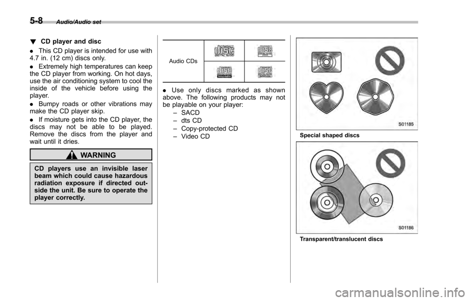
Audio CDs
. Use only discs marked as shown
above. The following products may not
be playable on your player:
–SACD
– dts CD
– Copy-protected CD
– Video CD
Special shaped discs
Transparent/translucent discs
5-8
Page 439 of 594
Starting and operating/BSD/RCTA (5–door models —if equipped)
&BSD/RCTA approach indica-
tor light/warning buzzer
When the BSD/RCTA is active, the BSD/
RCTA approach indicator light will operate
to alert the driver when there are vehicles
in the neighboring lanes. When reversing
the vehicle, the BSD/RCTA approach
indicator light and warning buzzer will
operate to alert the driver that a vehicle
is approaching from the left or right side.
! BSD/RCTA approach indicator light
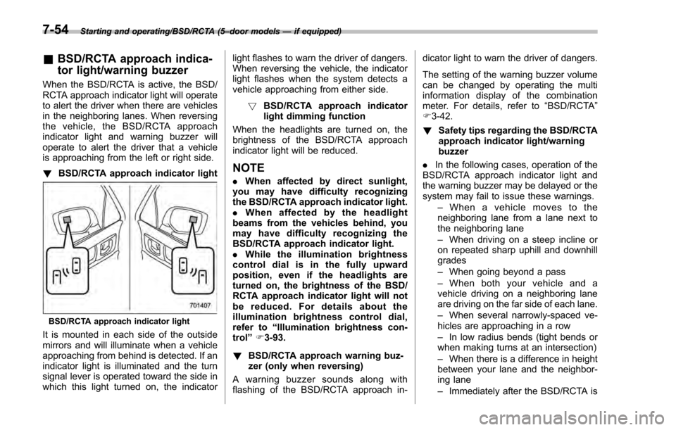
BSD/RCTA approach indicator light
It is mounted in each side of the outside
mirrors and will illuminate when a vehicle
approaching from behind is detected. If an
indicator light is illuminated and the turn
signal lever is operated toward the side in
which this light turned on, the indicator light flashes to warn the driver of dangers.
When reversing the vehicle, the indicator
light flashes when the system detects a
vehicle approaching from either side.
! BSD/RCTA approach indicator
light dimming function
When the headlights are turned on, the
brightness of the BSD/RCTA approach
indicator light will be reduced.
NOTE
. When affected by direct sunlight,
you may have difficulty recognizing
the BSD/RCTA approach indicator light.
. When affected by the headlight
beams from the vehicles behind, you
may have difficulty recognizing the
BSD/RCTA approach indicator light.
. While the illumination brightness
control dial is in the fully upward
position, even if the headlights are
turned on, the brightness of the BSD/
RCTA approach indicator light will not
be reduced. For details about the
illumination brightness control dial,
refer to “Illumination brightness con-
trol” F3-93.
! BSD/RCTA approach warning buz-
zer (only when reversing)
A warning buzzer sounds along with
flashing of the BSD/RCTA approach in- dicator light to warn the driver of dangers.
The setting of the warning buzzer volume
can be changed by operating the multi
information display of the combination
meter. For details, refer to
“BSD/RCTA”
F 3-42.
! Safety tips regarding the BSD/RCTA
approach indicator light/warning
buzzer
. In the following cases, operation of the
BSD/RCTA approach indicator light and
the warning buzzer may be delayed or the
system may fail to issue these warnings.
–When a vehicle moves to the
neighboring lane from a lane next to
the neighboring lane
– When driving on a steep incline or
on repeated sharp uphill and downhill
grades
– When going beyond a pass
– When both your vehicle and a
vehicle driving on a neighboring lane
are driving on the far side of each lane.
– When several narrowly-spaced ve-
hicles are approaching in a row
– In low radius bends (tight bends or
when making turns at an intersection)
– When there is a difference in height
between your lane and the neighbor-
ing lane
– Immediately after the BSD/RCTA is
7-54
Page 459 of 594
Driving tips/Trailer hitch (Crosstrek models—dealer option)
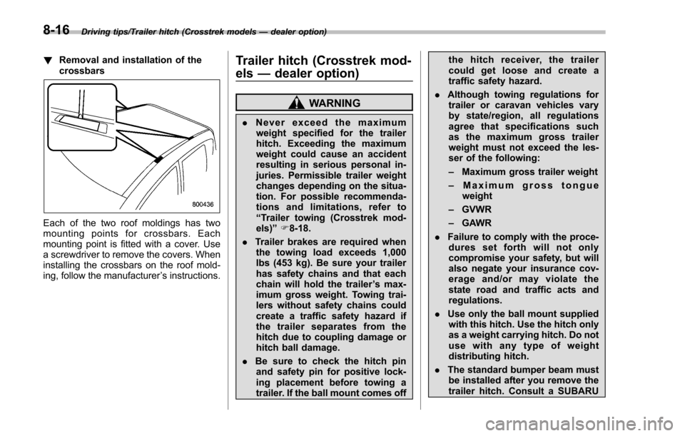
! Removal and installation of the
crossbars
Each of the two roof moldings has two
mounting points for crossbars. Each
mounting point is fitted with a cover. Use
a screwdriver to remove the covers. When
installing the crossbars on the roof mold-
ing, follow the manufacturer ’s instructions.
Trailer hitch (Crosstrek mod-
els —dealer option)
WARNING
. Never exceed the maximum
weight specified for the trailer
hitch. Exceeding the maximum
weight could cause an accident
resulting in serious personal in-
juries. Permissible trailer weight
changes depending on the situa-
tion. For possible recommenda-
tions and limitations, refer to
“Trailer towing (Crosstrek mod-
els) ”F 8-18.
. Trailer brakes are required when
the towing load exceeds 1,000
lbs (453 kg). Be sure your trailer
has safety chains and that each
chain will hold the trailer ’s max-
imum gross weight. Towing trai-
lers without safety chains could
create a traffic safety hazard if
the trailer separates from the
hitch due to coupling damage or
hitch ball damage.
. Be sure to check the hitch pin
and safety pin for positive lock-
ing placement before towing a
trailer. If the ball mount comes off the hitch receiver, the trailer
could get loose and create a
traffic safety hazard.
. Although towing regulations for
trailer or caravan vehicles vary
by state/region, all regulations
agree that specifications such
as the maximum gross trailer
weight must not exceed the les-
ser of the following:
– Maximum gross trailer weight
– Maximum gross tongue
weight
– GVWR
– GAWR
. Failure to comply with the proce-
dures set forth will not only
compromise your safety, but will
also negate your insurance cov-
erageand/ormayviolatethe
state road and traffic acts and
regulations.
. Use only the ball mount supplied
with this hitch. Use the hitch only
as a weight carrying hitch. Do not
use with any type of weight
distributing hitch.
. The standard bumper beam must
be installed after you remove the
trailer hitch. Consult a SUBARU
8-16
Page 460 of 594
dealer for purchase of a standard
bumper beam if you do not have
the original.
. Safety performance is decreased
and there is increased risk of
injury to passengers in the case
of an accident if the trailer hitch
or a standard bumper beam is
not installed. One of them must
always be installed on the vehi-
cle.
. If a trailer hitch is installed, it is
not possible to install the rear
towing hook.
The maximum gross trailer weight and
maximum gross tongue weight are indi-
cated in the following table.
Maximum
gross trailer
weight Maximum
gross ton-
gue weight
Crosstrek models 1,500 lbs
(680 kg) 200 lbs
(90 kg)
When towing a trailer, refer to “Trailer
towing (Crosstrek models) ”F 8-18.
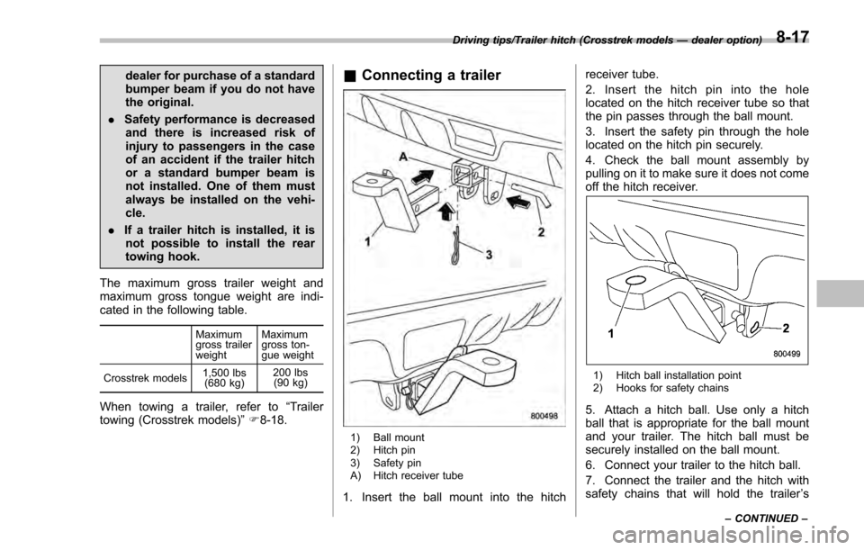
& Connecting a trailer
1) Ball mount
2) Hitch pin
3) Safety pin
A) Hitch receiver tube
1. Insert the ball mount into the hitch receiver tube.
2. Insert the hitch pin into the hole
located on the hitch receiver tube so that
the pin passes through the ball mount.
3. Insert the safety pin through the hole
located on the hitch pin securely.
4. Check the ball mount assembly by
pulling on it to make sure it does not come
off the hitch receiver.
1) Hitch ball installation point
2) Hooks for safety chains
5. Attach a hitch ball. Use only a hitch
ball that is appropriate for the ball mount
and your trailer. The hitch ball must be
securely installed on the ball mount.
6. Connect your trailer to the hitch ball.
7. Connect the trailer and the hitch with
safety chains that will hold the trailer
’s
Driving tips/Trailer hitch (Crosstrek models —dealer option)
–CONTINUED –8-17
Page 531 of 594
Maintenance and service/Installation of accessories
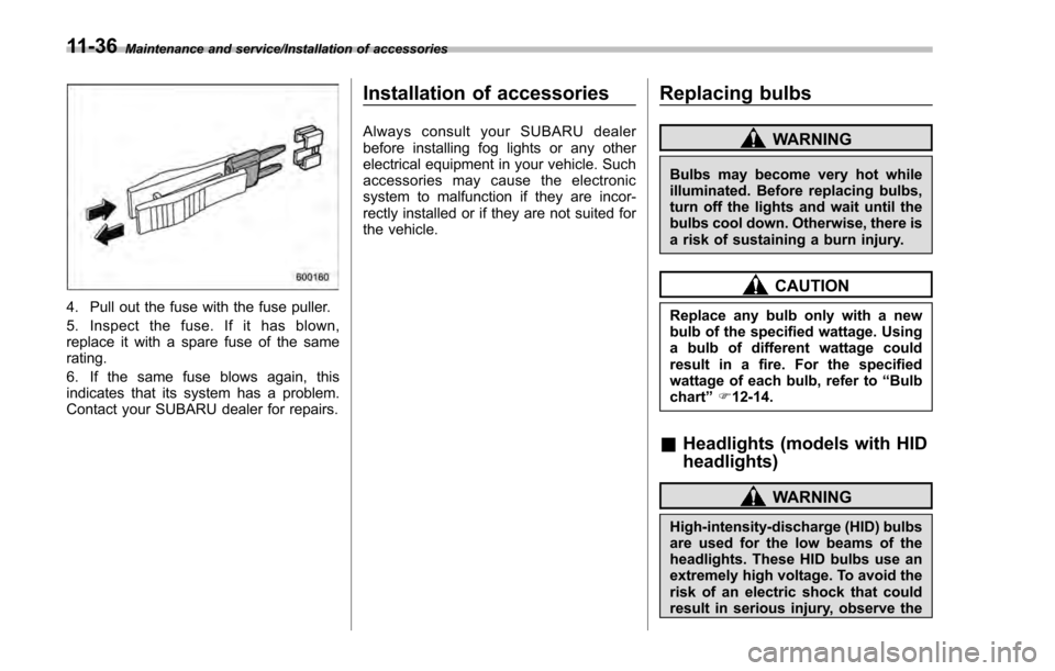
4. Pull out the fuse with the fuse puller.
5. Inspect the fuse. If it has blown,
replace it with a spare fuse of the same
rating.
6. If the same fuse blows again, this
indicates that its system has a problem.
Contact your SUBARU dealer for repairs.
Installation of accessories
Always consult your SUBARU dealer
before installing fog lights or any other
electrical equipment in your vehicle. Such
accessories may cause the electronic
system to malfunction if they are incor-
rectly installed or if they are not suited for
the vehicle.
Replacing bulbs
WARNING
Bulbs may become very hot while
illuminated. Before replacing bulbs,
turn off the lights and wait until the
bulbs cool down. Otherwise, there is
a risk of sustaining a burn injury.
CAUTION
Replace any bulb only with a new
bulb of the specified wattage. Using
a bulb of different wattage could
result in a fire. For the specified
wattage of each bulb, refer to“Bulb
chart” F12-14.
& Headlights (models with HID
headlights)
WARNING
High-intensity-discharge (HID) bulbs
are used for the low beams of the
headlights. These HID bulbs use an
extremely high voltage. To avoid the
risk of an electric shock that could
result in serious injury, observe the
11-36
Page 532 of 594
following precautions.
.Do not replace any headlight
bulbs (both low beam and high
beam) by yourself.
. Do not remove/restore the head-
light assemblies by yourself.
. Do not remove any headlight-
assembly components by your-
self.
For replacement, contact your
SUBARU dealer.
& Headlights (models without
HID headlights)
CAUTION
Halogen headlight bulbs become
very hot while in use. If you touch
the bulb surface with bare hands or
greasy gloves, fingerprints or
grease on the bulb surface will
develop into hot spots, causing the
bulb to break. If there are finger
prints or grease on the bulb surface,
wipe them away with a soft cloth
moistened with alcohol.
NOTE
. If headlight aiming is required, con-
sult your SUBARU dealer for proper
adjustment of the headlight aim.
. It may be difficult to replace the
bulbs. Have the bulbs replaced by your
SUBARU dealer if necessary.
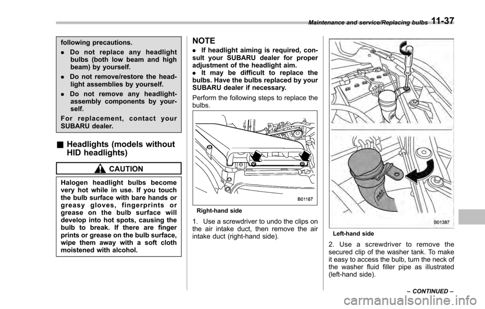
Perform the following steps to replace the
bulbs.
Right-hand side
1. Use a screwdriver to undo the clips on
the air intake duct, then remove the air
intake duct (right-hand side).
Left-hand side
2. Use a screwdriver to remove the
secured clip of the washer tank. To make
it easy to access the bulb, turn the neck of
the washer fluid filler pipe as illustrated
(left-hand side).
Maintenance and service/Replacing bulbs
–CONTINUED –11-37