2016 SUBARU IMPREZA check engine light
[x] Cancel search: check engine lightPage 168 of 594

dealer.
! Hill start assist OFF indicator light
While the Hill start assist system is
deactivated, the Hill start assist OFF
indicator light illuminates continuously to
inform the driver that the Hill start assist
system is not operational.
&Door open warning
light
The warning light illuminates if any door,
the rear gate (5-door models) or trunk lid
(4-door models) is not fully closed. This
function is effective even if the ignition
switch is in the “LOCK”/ “OFF”or “ACC ”
position, or the key is removed from the
ignition switch.
Always make sure this light is not illumi-
nated before you start to drive.
&All-Wheel Drive warn-
ing light (CVT models)
This light blinks if the vehicle is driven with
tires of differing diameters fitted on the
wheels or with an excessively low air
pressure in any of the tires.
WARNING
If the AWD warning light flashes,
promptly park in a safe location then
check whether all four tires are the
same diameter and whether any of
the tires has a puncture or has lost
air pressure for some other reason.
Continuing to drive with the AWD
warning light flashing can lead to
powertrain damage.
&Power steering warn-
ing light
This warning light illuminates when the
ignition switch is turned to the “ON ”
position and turns off after the engine
has started. This indicates that the warn-
ing system is working properly.
While the engine is running, this warning
light illuminates when a malfunction has
been detected in the electric power steer-
ing system.
CAUTION
When the power steering warning
light is illuminated, there may be
more resistance when the steering
wheel is operated. Drive carefully to the nearest SUBARU dealer and
have the vehicle inspected immedi-
ately.
NOTE
If the steering wheel is operated in the
following ways, the power steering
control system may temporarily limit
the power assist in order to prevent the
system components, such as the con-
trol computer and drive motor, from
overheating.
.
The steering wheel is operated fre-
quently and turned sharply while the
vehicle is maneuvered at extremely low
speeds, such as while frequently turn-
ing the steering wheel during parallel
parking.
. The steering wheel remains in the
fully turned position for a long period
of time.
At this time, there will be more resis-
tance when steering. However this is
not a malfunction. Normal steering
force will be restored after the steering
wheel is not operated for a while and
the power steering control system has
an opportunity to cool down. However,
if the power steering is operated in a
non-standard way which causes power
assist limitation to occur too fre-
Instruments and controls/Warning and indicator lights
–CONTINUED –3-23
Page 169 of 594

Instruments and controls/Warning and indicator lights
quently, that may result in a malfunc-
tion of the power steering control
system.
&Vehicle Dynamics
Control warning light/
Vehicle Dynamics Con-
trol operation indicator
light
!Vehicle Dynamics Control warning
light
CAUTION
The Vehicle Dynamics Control sys-
tem provides its ABS control
through the electrical circuit of the
ABS. Accordingly, if the ABS is
inoperative, the Vehicle Dynamics
Control system becomes unable to
provide ABS control. As a result, the
Vehicle Dynamics Control system
also becomes inoperative, causing
the warning light to illuminate.
Although both the Vehicle Dynamics
Control system and ABS are inop-
erative in this case, the ordinary
functions of the brake system are
still available. You will be safe while
driving with this condition, but drive carefully and have your vehicle
checked at a SUBARU dealer as
soon as possible.
NOTE
.
If the electrical circuit of the Vehicle
Dynamics Control system itself mal-
functions, the warning light only illumi-
nates. At this time, the ABS (Anti-lock
Brake System) remains fully opera-
tional.
. The warning light illuminates when
the electronic control system of the
ABS/Vehicle Dynamics Control system
malfunctions.
The Vehicle Dynamics Control system is
probably inoperative under any of the
following conditions. Have your vehicle
checked at a SUBARU dealer immedi-
ately.
. The warning light does not illuminate
when the ignition switch is turned to the
“ON ”position.
. The warning light illuminates while the
vehicle is running.
NOTE
If the warning light behavior is as
described in the following examples,
the Vehicle Dynamics Control system
may be considered normal. .
The warning light illuminates when
the ignition switch is turned to the
“ON ”position and turns off approxi-
mately 2 seconds after the engine has
started.
. The warning light illuminates right
after the engine is started but turns off
immediately, remaining off.
. The warning light illuminates after
the engine has started and turns off
while the vehicle is subsequently being
driven.
. The warning light illuminates during
driving, but it turns off immediately and
remains off.
. The warning light illuminates when
the engine has stalled and continues to
illuminate after the engine has been
restarted. However, it will turn off once
the vehicle starts moving.
! Vehicle Dynamics Control opera-
tion indicator light
The indicator light flashes during activa-
tion of the skid suppression function and
during activation of the traction control
function.NOTE
. The light may remain illuminated for
a short period of time after the engine
has been started, especially in cold
weather. This does not indicate the
3-24
Page 170 of 594

existence of a problem. The light
should turn off as soon as the engine
has warmed up.
.The indicator light illuminates when
the engine has developed a problem
and the CHECK ENGINE warning light/
malfunction indicator light is on.
The Vehicle Dynamics Control system is
probably malfunctioning under the follow-
ing condition. Have your vehicle checked
at a SUBARU dealer as soon as possible.
. The light does not turn off even after
the lapse of several minutes (the engine
has warmed up) after the engine has
started.
&Vehicle Dynamics
Control OFF indicator
light
The light illuminates when the Vehicle
Dynamics Control OFF switch is pressed
to deactivate the Vehicle Dynamics Con-
trol system.
The Vehicle Dynamics Control system is
probably malfunctioning under any of the
following conditions. Have your vehicle
checked at a SUBARU dealer immedi-
ately.
. The light does not illuminate when the
ignition switch is turned to the “ON ”
position. .
The light does not turn off even once
several seconds have elapsed after the
ignition switch has been turned to the
“ON ”position.
& Warning chimes and warning
indicator of the keyless ac-
cess with push-button start
system (if equipped)
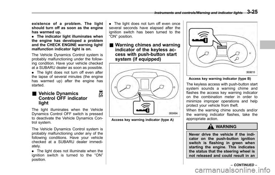
Access key warning indicator (type A)
Access key warning indicator (type B)
The keyless access with push-button start
system sounds a warning chime and
flashes the access key warning indicator
on the combination meter in order to
minimize improper operations and help
protect your vehicle from theft.
When the warning chime sounds and/or
the warning indicator flashes, take the
appropriate action.
WARNING
Never drive the vehicle if the indi-
cator on the push-button ignition
switch is flashing in green when
starting the engine. This indicates
the status that the steering wheel is
not released and could result in an
Instruments and controls/Warning and indicator lights
–CONTINUED –3-25
Page 176 of 594

Type B
1) Upshift indicator
2) Downshift indicator
3) Select lever/gear position indicator
This indicator shows the position of the
select lever.
For models with manual mode, when the
manual mode is selected, the gear posi-
tion indicator (which shows the current
gear selection) and the upshift/downshift
indicator light up. Refer to“Continuously
variable transmission ”F 7-23.
&Turn signal indicator
lights
These lights show the operation of the turn
signal or lane change signal.
If the indicator lights do not blink or blink rapidly, the turn signal bulb may be burned
out. Replace the bulb as soon as possible.
Refer to
“Replacing bulbs ”F 11-36.
&High beam indicator
light
This light shows that the headlights are in
the high beam mode.
This indicator light also illuminates when
the headlight flasher is operated.
&Cruise control indica-
tor light (if equipped)
This light illuminates when the cruise
control main button is pressed to activate
the cruise control function. For details,
refer to “To set cruise control” F7-45.
CAUTION
If the CHECK ENGINE warning light/
malfunction indicator light illumi-
nates, the cruise control indicator
light flashes at the same time. At
this time, avoid driving at high
speed and have your vehicle in-
spected at a SUBARU dealer as
soon as possible.
&Cruise control set in-
dicator light (if
equipped)
This light illuminates when vehicle speed
has been set to use the cruise control
function. Refer to “To set cruise control ”
F 7-45.
&Automatic headlight
beam leveler warning
light (models with HID
headlights)
This light illuminates when the automatic
headlight beam leveler does not operate
normally.
If this light illuminates while driving or does
not turn off approximately 3 seconds after
turning the ignition switch to the “ON”
position, have your vehicle inspected at
your SUBARU dealer.
&Front fog light indicator
light (if equipped)
This indicator light illuminates while the
front fog lights are illuminated.
Instruments and controls/Warning and indicator lights
–CONTINUED –3-31
Page 200 of 594

Top menuMenu option DescriptionPage
Maintenance Engine Oil Set and adjust the oil maintenance notification date. 3-74
Oil Filter Set and adjust the oil filter maintenance notification date. 3-75
Tires Set and adjust the tire maintenance notification date. 3-75
Maintenance Schedule Set and adjust the vehicle maintenance notification date. 3-75
On/Off Turn on or off the self-check screen that is
activated when the ignition switch is turned to
the
“ON ”position. On or Off
3-75
Clear All Settings Clear all settings for maintenance items. Yes or No 3-76
Go Back Return to the top menu. —
Driving History Set Register and overwrite the driving record. 3-77
Go Back Return to the top menu. —
Car Setting Keyless Buzzer Volume Set the audible signal volume. 0 (OFF) to 73-79
Hazard Warning Flasher Set the hazard warning flasher. On or Off3-79
Defogger Set and customize the operation of the defogger. 15 minutes or Continuous 3-80
Interior Light Set and customize the interior light off delay
timer. 10, 20, 30 seconds or Off
3-82
Auto Light Sensor (if equipped) Set and customize the sensitivity of the auto
light sensor.
Low, Mid, High or Max
3-83
Keyless Access Setting (if
equipped) Set and customize the keyless access function. Driver
’s Door Unlock 3-84
Rear Gate Unlock 3-85
Go Back Return to top menu. —
Instruments and controls/Multi function display
–CONTINUED –
3-55
Page 258 of 594

Ventilator control................................................. 4-2Center and side ventilators .................................. 4-2
Climate control panel.......................................... 4-3Type A ................................................................ 4-3
Type B ................................................................ 4-4
Type C ................................................................ 4-5
Type D ................................................................ 4-6
Automatic climate control operation (type
B, C and D) ....................................................... 4-7
Type B ................................................................ 4-7
Type C and D ...................................................... 4-7
Operation tips ..................................................... 4-7
Sensors .............................................................. 4-8
Manual climate control operation ...................... 4-8Airflow mode selection........................................ 4-8
Temperature control ............................................ 4-9
Fan speed control .............................................. 4-10
Air conditioner control ....................................... 4-10
Air inlet selection ............................................... 4-10
Defrosting........................................................... 4-11Type A and B..................................................... 4-11
Type C............................................................... 4-11
Type D............................................................... 4-11
Operating tips for heater and air
conditioner ...................................................... 4-11
Cleaning ventilation grille ................................... 4-11
Efficient cooling after parking in direct sunlight ........................................................... 4-11
Lubrication oil circulation in the refrigerant circuit .............................................................. 4-12
Checking air conditioning system before summer season ............................................................ 4-12
Cooling and dehumidifying in high humidity and low temperature weather conditions ................. 4-12
Air conditioner compressor shut-off when engine is heavily loaded .............................................. 4-12
Refrigerant for your climate control system ... ..... 4-12
Air filtration system........................................... 4-12Replacing an air filter ......................................... 4-13
Climate control
4
Page 381 of 594

Interior equipment/Rear view camera
.Since the range of the image on
the monitor is limited, you should
always check the rear view and
the surrounding area with your
eyes and mirrors, and move
backward at a slow speed. Mov-
ing backward only by checking
the rear view image from the
camera could cause an accident.
. Do not disassemble or modify the
camera, switch or wiring. If
smoke comes out or you smell
a strange odor, stop using the
rear view camera immediately.
Contact your SUBARU dealer
for an inspection. Continued use
may result in accident, fire or
electric shock.
CAUTION
. If your vehicle is washed with a
high-pressure washer, do not
allow water to contact the camera
directly. Entry of water in the
camera lens may result in con-
densation, malfunction, fire or
electric shock.
. Since the camera is a precision
device, do not subject it to strong
impacts. Otherwise, malfunction, fire or electric shock may occur.
. If mud or snow sticks to or is
frozen on the camera, you must
be very careful when removing it.
Otherwise, damage to the camera
may cause a fire or electric
shock. Pour water or lukewarm
water over the camera to remove
mud and ice, and wipe it with a
soft, dry cloth.
. Do not put a flame close to the
camera or wiring. Otherwise, da-
mage or fire may occur.
. When replacing the fuse, be sure
to use a fuse with the specified
rating. Use of a fuse with a
different rating may result in a
malfunction.
. If the rear view camera is used for
a long time while the engine is
not operated, the battery may
become completely discharged.
NOTE
. Do not wipe the camera with alcohol,
benzine or paint thinner. Otherwise,
discoloration may occur. To remove
contamination, wipe the camera with a
cloth moistened with a diluted neutral
detergent and then wipe it with a soft, dry cloth.
.
When waxing the vehicle, be careful
not to apply the wax to the camera. If it
comes in contact with the camera,
moisten a clean cloth with a diluted
neutral detergent to remove the wax.
. The camera lens has a hard coating
to help prevent scratches. However,
when washing the vehicle or cleaning
the camera lens, be careful not to
scratch the camera lens. Do not use a
washing brush directly on the camera
lens. The image quality of the rear view
camera may deteriorate.
. Strong light shined on the camera
lens may develop vertical lines around
the light source. This is not a malfunc-
tion.
. Under fluorescent light, the display
may flicker. However, this is not a
malfunction.
. The image of the rear view camera
may be slightly different from the
actual color of the objects.
6-16
Page 386 of 594

Fuel...................................................................... 7-3Fuel requirements ............................................... 7-3
Fuel filler lid and cap ........................................... 7-4
State emission testing (U.S. only) ...................... 7-7
Preparing to drive ............................................... 7-8
Starting and stopping the engine (models without push-button start system) .................. 7-9
Starting engine.................................................... 7-9
Stopping the engine ........................................... 7-11
Starting and stopping engine (models with
push-button start system) .............................. 7-12
Safety precautions............................................. 7-12
Operating range for push-button start system ............................................................. 7-12
Starting engine ................................................... 7-12
Stopping engine ................................................. 7-13
When access key does not operate properly ....... 7-14
Remote engine start system (dealer
option) .............................................................. 7-14
Models with “keyless access with push-button
start system ”................................................... 7-15
Models without “keyless access with push-button
start system ”................................................... 7-16
Entering the vehicle while it is running via remote start ................................................................. 7-19
Entering the vehicle following remote engine start shutdown ......................................................... 7-19
Pre-heating or pre-cooling the interior of the vehicle ............................................................. 7-19
Service mode (models without “keyless access
with push-button start system ”)........................ 7-19 Remote transmitter program (models without
“keyless access with push-button start
system ”).......................................................... 7-19
System maintenance .......................................... 7-20
Manual transmission ......................................... 7-22Shifting speeds.................................................. 7-22
Driving tips ........................................................ 7-23
Continuously variable transmission ................. 7-23Continuously variable transmission features . ..... 7-24
Select lever ....................................................... 7-24
Selection of manual mode (if equipped) .............. 7-26
Selection of “L”(if equipped) ... .......................... 7-28
Shift lock function ............................................. 7-28
Driving tips ........................................................ 7-29
Power steering ................................................... 7-30Power steering warning light .............................. 7-30
Power steering system features ......................... 7-30
Braking............................................................... 7-31Braking tips ....................................................... 7-31
Brake system .................................................... 7-31
Disc brake pad wear warning indicators ............. 7-32
ABS (Anti-lock Brake System).......................... 7-32ABS self-check.................................................. 7-32
ABS warning light .............................................. 7-33
Electronic Brake Force Distribution (EBD)
system ............................................................. 7-33
Steps to take if EBD system malfunctions .......... 7-33
Vehicle Dynamics Control system.................... 7-34Safety precautions............................................. 7-34
System features ................................................. 7-35
Vehicle Dynamics Control system monitor .......... 7-36
Starting and operating
7