2016 Seat Ibiza SC heating
[x] Cancel search: heatingPage 142 of 248
Operation
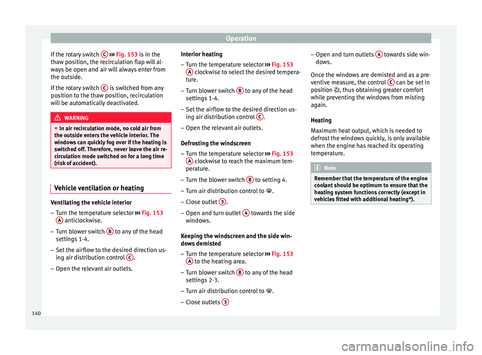
If the rotary switch C
› ››
Fig. 153
i s in the
thaw position, the recirculation flap will al-
ways be open and air will always enter from
the outside.
If the rotary switch C is switched from any
po s
ition t
o the thaw position, recirculation
will be automatically deactivated. WARNING
● In air rec ir
culation mode, no cold air from
the outside enters the vehicle interior. The
windows can quickly fog over if the heating is
switched off. Therefore, never leave the air re-
circulation mode switched on for a long time
(risk of accident). Vehicle ventilation or heating
Ventilating the vehicle interior
– Turn the temperature selector ››
›
Fig. 153
A anticlockwise.
– Turn blower switch B to any of the head
settin g
s
1-4.
– Set the airflow to the desired direction us-
ing air dis
tribution control C .
– Open the relevant air outlets. Interior heating
– Turn the temperature selector ››
›
Fig. 153
A clockwise to select the desired tempera-
t ur
e.
– T
urn blower switch B to any of the head
settin g
s
1-4.
– Set the airflow to the desired direction us-
ing air dis
tribution control C .
– Open the relevant air outlets.
D efr
o
sting the windscreen
– Turn the temperature selector ›››
Fig. 153
A clockwise to reach the maximum tem-
per at
ur
e.
– Turn the blower switch B to setting 4.
– Turn air distribution control to .
– Close outlet 3 .
– Open and turn outlet 4 towards the side
w indo
w
s.
Keeping the windscreen and the side win-
dows demisted
– Turn the temperature selector ›››
Fig. 153
A to the heating area.
– Turn blower switch B to any of the head
settin g
s
2-3.
– Turn air distribution control to .
– Close outlets 3 –
Open and t urn outl
ets
4 towards side win-
do w
s.
Onc
e the windows are demisted and as a pre-
ventive measure, the control C can be set in
po s
ition
, thus obtaining greater comfort
while preventing the windows from misting
again.
Heating
Maximum heat output, which is needed to
defrost the windows quickly, is only available
when the engine has reached its operating
temperature. Note
Remember that the temperature of the engine
coo l
ant should be optimum to ensure that the
heating system functions correctly (except in
vehicles fitted with additional heating*). 140
Page 143 of 248

Air conditioning
Air conditioning* C ontr
o
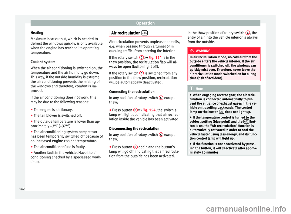
ls Fig. 154
Air conditioning controls on the
d a
sh p
anel. Temperature selector
››
›
page 141
Blower control. There are four speed set-
tings for the blower. At low speed, it is
recommended to set the blower to a mini-
mum of 1 to improve the intake of fresh
air.
Air distribution control ››› page 141
Air recirculation button
› ›
› p
age 142
A/C button – Switches on the cooling
sy s
t
em ››› page 141
The air conditioning system only works when
the engine is running and the fan is switched
on. A B
C
D
E ●
Us
in
g the rotary switches A ,
B and
C ›››
Fig. 154 y ou c
an a djust temperature, blow-
er speed and air distribution.
● To switch a function on or off, press the ap-
propriat
e button D or
E . When the function
i s
activ
ated, a red warning light on the but-
ton is turned on.
To demist the windscreen
● Turn air distribution to .
● Turn the fan control to one of the two levels
depending on the speed r
equired.
● Rotate the temperature control to the de-
sired l
evel of comfort.
● Close outlets 3 ●
Open and turn outlets 4 towards side win-
do w
s. WARNING
For your safety, the windows should never be
fog g
ed up or covered with snow or ice. This is
essential to ensure good visibility. Please fa-
miliarise yourself with the correct operation
of the heating and ventilation system, includ-
ing the demist/defrost functions for the win-
dows. Note
Please consider the general notes. Vehicle interior heating or cooling
sy
s
t
em Interior heating
– Turn off the cooling system using the
›› ›
Fig. 154 A/C button (the button light
turn s
off).
– Turn the temperature selector A to set the
des ir
ed temperature inside the vehicle.
– Turn the blower switch to any of the set-
tings
1-4.
– Set the air distribution control C to the air
flo w c
onfigur
ation desired: (towards the
w ind
s
creen), (towards the chest),
(towards the footwell) and
(towards the
w ind
s
creen and footwell areas).
Interior cooling
– Turn off the cooling system using the A/C button (the button light turns on).
– Turn the temperature control switch until
the de s
ir
ed interior temperature is reached.
– Turn the blower switch to any of the set-
tings
1-4.
– Set the air distribution control to the air
flow configur
ation desired: (towards the
w ind
s
creen), (towards the chest),
(towards the footwell) and
(towards the
w ind
s
creen and footwell areas). »
141
Technical data
Advice
Operation
Emergencies
Safety
Page 144 of 248
Operation
Heating
M ax
imum he
at output, which is needed to
defrost the windows quickly, is only available
when the engine has reached its operating
temperature.
Coolant system
When the air conditioning is switched on, the
temperature and the air humidity go down.
This way, if the outside humidity is extreme,
the air conditioning prevents the misting of
the windows and therefore, comfort is im-
proved.
If the air conditioning does not work, this
may be due to the following reasons:
● The engine is stationary.
● The fan blower is switched off.
● The outside temperature is lower than ap-
prox
imately +3°C (+37°F).
● The air conditioning system compressor
has
been temporarily switched off because of
an increased engine coolant temperature.
● The air conditioner fuse is faulty.
● Another fault in the vehicle. Have the air
conditioning c
hecked by a specialised work-
shop. Air recirculation
Air recirculation prevents unpleasant smells,
e.g. when p
a
ssing through a tunnel or in
queuing traffic, from entering the interior.
If the rotary switch C
››› Fig. 154 i
s in the
thaw position, the recirculation flap will al-
ways be open (button light off).
If the rotary switch C is switched from any
pos ition t
o the thaw position, recirculation
will be automatically deactivated.
Connecting the recirculation
In any position of rotary switch C except
th a
w:
● Pr
ess button D
› ›
› Fig. 154
, the switch's
lamp will light up, indicating that air recircu-
lation inside the vehicle has been activated.
Disconnecting the recirculation
In any position of rotary switch C except
th a
w:
● Pr
ess button D again and the button's
l amp w
i
ll go off, indicating that air recircula-
tion from the outside has been activated. In the thaw position of rotary switch
C , the
entr y
of
air into the vehicle interior is always
from the outside. WARNING
In air recirculation mode, no cold air from the
outs ide ent
ers the vehicle interior. If the air
conditioner is switched off, the windows can
quickly mist over. Therefore, never leave the
air recirculation mode switched on for a long
time (risk of accident). Note
● When eng agin
g reverse gear, the air recir-
culation is connected automatically to pre-
vent the entrance of exhaust gases in the ve-
hicle on travelling backwards. The control
lamp on the button does not light up.
● If the temperature control is turned to the
co l
dest setting (blue point) and the A/C but-
ton i s
on, the “Air recirculation” function is
automatically activated in order to cool the
vehicle faster using less energy, and its func-
tion control lamp will light up.
● If the function is not deactivated by press-
ing the butt
on, it will deactivate after approx-
imately 20 minutes. 142
Page 146 of 248

Operation
● Pr e
s
s the AUTO button
13
› ››
Fig. 155
.
● Adju
st vents 3 and 4 ›››
page 138 so that
the air flow is directed slightly upwards.
Change between degrees Centigrade and de-
grees Fahrenheit
Keep the AUTO and
A/C
› ››
Fig. 155
b
uttons
held down for 2 seconds at the same time.
The data is displayed on the screen in the
units required. Note
● A v i
sit to the specialised service once a
year is recommended to clean the Climatronic
system.
● The interior temperature sensor 11›››
Fig. 155 is at
the bottom. Do not cover it
with stickers or the like, as this could have a
negative effect on Climatronic operations. Automatic mode
Automatic mode is used to maintain a con-
s
t
ant
temperature and demist the windows
inside the vehicle.
Switching on automatic mode
● Set the interior temperature between +16°C
(+64°F) and +29°C (+84°F).
● Adjus
t vents 3 and 4 ›››
page 138 so that
the air flow is directed slightly upwards. ●
Pres
s the AUTO button
13
› ››
Fig. 155
and
AUTO di
splayed on the screen.
Automatic mode is switched off by pressing
the air distribution buttons or increasing or
decreasing the blower speed. However, the
temperature remains regulated.
Adjusting the temperature ●
When you switch on the ignition, control 1 ›››
Fig. 155 can be u sed t
o set the required in-
terior temperature.
It is possible to select interior temperatures
from +16°C (+64°F) to +29°C (+84°F). In this
range the temperature is regulated automati-
cally. If a temperature below +16°C (+64°F) is
selected, “LO” is displayed on the screen. If a
temperature above +29°C (+84°F) is selected,
“HI” is displayed on the screen. At both ex-
tremes, Climatronic works at maximum cool-
ing or heating power, respectively. The tem-
perature is not regulated.
In the event of prolonged, irregular distribu-
tion of the air flow from the outlets (particu-
larly the footwells) and significant differen-
ces in temperature, e.g. on leaving the vehi-
cle, sensitive people may catch cold. Air recirculation Air recirculation prevents unpleasant smells,
e.g. when p
a
ssing through a tunnel or in
queuing traffic, from entering the interior.
Switching on air recirculation mode
● Press button
17
››› Fig. 155 and the
symbol is displayed on the screen.
Switching off air recirculation mode
● Press button
17
› ›
› Fig. 155
and the
symbol disappears from the screen. WARNING
Read and observe the safety warnings ›››
in
Genera l
notes on page 137. Note
If air recirculation mode remains on for 15 mi-
nute s, the
symbol will start to flash on
the screen to indicate prolonged air recircula-
tion. If air recirculation is not switched off,
the symbol will continue to flash for about 5
minutes. Blower selection
Climatronic automatically regulates blower
s
peed ac
c
ording to the interior temperature.
144
Page 150 of 248
Operation
Note
A perfect operation of the vehicle is ensured
if g enuine
SEAT keys are used. Starting petrol engines
The engine can only be started using a genu-
ine S
EA
T key with its correct code.
– Move the gearbox lever to the neutral posi-
tion and depres
s the clutch pedal thor-
oughly and hold it in this position for the
starter to turn the engine on.
– Turn the ignition key to the starting posi-
tion ››
›
page 147.
– Let go of the ignition key as soon as the en-
gine star
ts; the starter motor must not run
on with the engine.
After starting a very hot engine, you may
need to slightly press down the accelerator.
When starting a cold engine, it may be a little
noisy for the first few seconds until oil pres-
sure has built up in the hydraulic valve com-
pensators. This is quite normal, and no cause
for concern.
If the engine does not start immediately,
switch the starter off after 10 seconds and try
again after half a minute. If the engine still
does not start, the fuel pump fuse should be
checked ›››
page 80, Fuses. WARNING
● Never s t
art or run the engine in unventila-
ted or closed rooms. The exhaust gases con-
tain carbon monoxide, an odourless and col-
ourless poisonous gas. Risk of fatal acci-
dents. Carbon monoxide can cause loss of
consciousness and result in death.
● Never leave the vehicle unattended if the
engine is
running.
● Never use “cold start sprays”, they could
explode or c
ause the engine to run at high
revs. Risk of injury. CAUTION
● When the engine i s
cold, you should avoid
high engine speeds, driving at full throttle
and over-loading the engine. Risk of engine
damage.
● The vehicle should not be pushed or towed
more than 50 metr
es to start the engine. Un-
burnt fuel could enter the catalytic converter
and damage it.
● Before attempting to push-start or tow a ve-
hicle in or
der to start it, you should first try to
start it using the battery of another vehicle.
Please observe and follow the notes on the
››› page 52, How to jump start. For the sake of the environment
Do not warm-up the engine by running the
engine w ith the
vehicle stationary. Start off
immediately, driving gently. This helps the engine reach operating temperature faster
and reduc
e
s emissions. Starting diesel engines
The engine can only be started using a genu-
ine S
EA
T key with its correct code.
– Move the gearbox lever to the neutral posi-
tion and depres
s the clutch pedal thor-
oughly and hold it in this position for the
starter to turn the engine on.
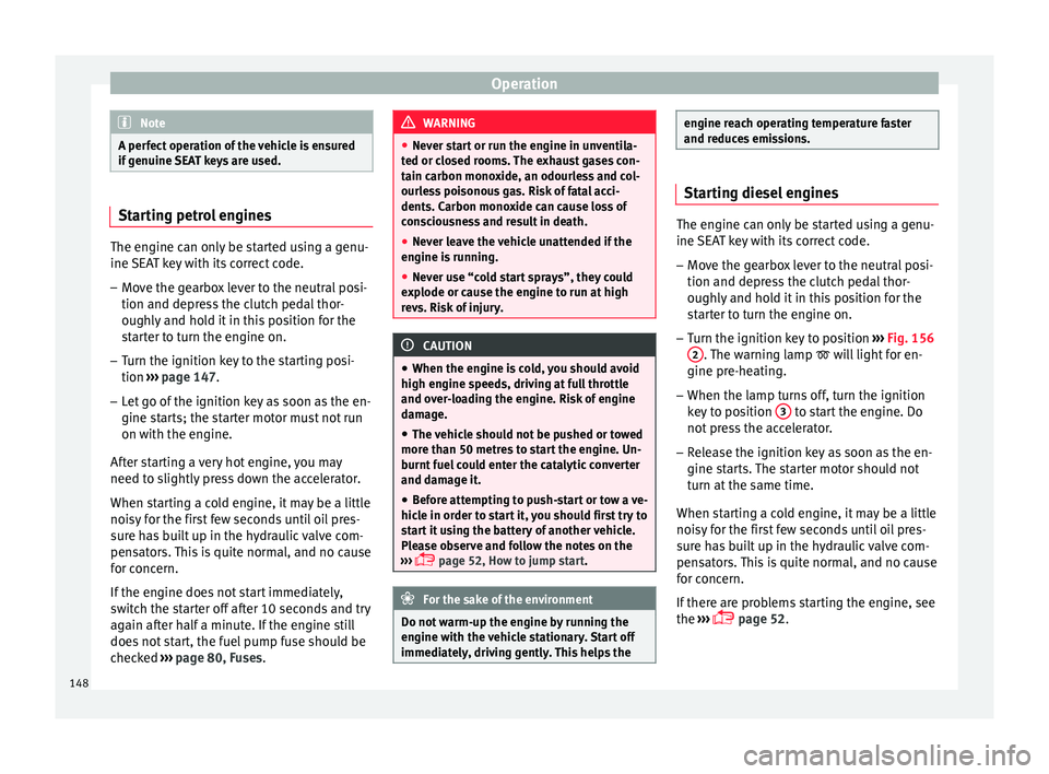
– Turn the ignition key to position ›››
Fig. 156
2 . The warning lamp
wi
l l light for en-
gine pre-heating.
– When the lamp turns off, turn the ignition
key t
o position 3 to start the engine. Do
not pr
e
ss the accelerator.
– Release the ignition key as soon as the en-
gine star
ts. The starter motor should not
turn at the same time.
When starting a cold engine, it may be a little
noisy for the first few seconds until oil pres-
sure has built up in the hydraulic valve com-
pensators. This is quite normal, and no cause
for concern.
If there are problems starting the engine, see
the ›››
page 52.
148
Page 157 of 248

Driving
At speeds of up to approximately 80 km/h
(50 mph), it i
s
able to balance out differences
in the speed of the driven wheels of approxi-
mately 100 rpm/min caused by a partially
slippery road surface. It does this by braking
the wheel which has lost traction and distrib-
uting more driving force to the other driven
wheel via the differential.
To prevent the disc brake of the braking
wheel from overheating, the EDL cuts out au-
tomatically if subjected to excessive loads.
The vehicle will continue to function normally
without EDL. For this reason, the driver is not
informed that the EDL has been switched off.
The EDL will switch on again automatically
when the brake has cooled down.
Control lamp
A malfunction in the EDL is indicated by the
ABS control lamp ››› page 155. Take the
vehicle to a specialised workshop as soon as
possible. WARNING
● When acc el
erating on a slippery surface,
for example on ice and snow, press the accel-
erator carefully. Despite EDL, the driven
wheels may start to spin. This could impair
the vehicle's stability.
● Always adapt your driving style to suit road
conditions
and the traffic situation. Do not let
the extra safety afforded by EDL tempt you in- to taking any risks when driving, this can
cau
se ac
cidents. CAUTION
Modifications to the vehicle (e.g. to the en-
gine, the br ake sy
stem, running gear or any
components affecting the wheels and tyres)
could affect the efficiency of the EDL
››› page 187. Hydraulic Brake Assist (HBA)*
The function (Hydraulic Brake Assist HBA) is
on
ly
inc
luded in vehicles with ESC.
In an emergency, most drivers brake in time,
but not with maximum force. This results in
unnecessarily long braking distances.
This is when the brake assist system comes
into action. When pressing the brake pedal
rapidly, the assistant interprets it as an emer-
gency. It very quickly builds up the full brake
pressure so that the ABS can be activated
more quickly and efficiently, thus reducing
braking distance.
Do not reduce the pressure on the brake ped-
al, since the brake assist system switches off
automatically as soon as you release the
brake. Automatic hazard warning lights activation
The brake lights
flash automatically to indi-
cate that the vehicle is braking suddenly or in
an emergency situation. If the emergency
braking continues until the vehicle comes to
a standstill, the hazard warning lights will
then come on and the brake lights will re-
main on permanently from that moment. The
warning lights will automatically switch off
when the vehicle begins to move again or
when the "warning" light button is pressed. WARNING
● The risk of
accident is higher if you drive
too fast, if you do not keep your distance from
the vehicle in front, and when the road sur-
face is slippery or wet. The increased acci-
dent risk cannot be reduced by the brake as-
sist system.
● The brake assist system cannot defy the
law
s of physics. Slippery and wet roads are
dangerous even with the brake assist system!
Therefore, it is essential that you adjust your
speed to suit the road and traffic conditions.
Do not let the extra safety features tempt you
into taking any risks when driving. Anti-lock brake system (ABS)
The anti-lock brake (ABS) system prevents
the wheel
s
fr
om locking during braking and
is an important part of the vehicle's active
safety system. »
155
Technical data
Advice
Operation
Emergencies
Safety
Page 169 of 248
Driving
exhaust can come into contact with flamma-
bl
e m
aterials under the car (e.g. on grass or
at the forest edge). Fire hazard!
● Do not apply wax underneath the vehicle
around the ar
ea of the exhaust system: Fire
hazard! Note
While the control lamps , , or r
e-
m ain lit, ther
e may be engine problems, fuel
consumption may increase and the engine
may lose power. Catalytic converter
To maintain the useful life of the catalytic
c
on
v
erter
– Use only unleaded petrol with petrol en-
gines, as
lead damages the catalytic con-
verter.
– Do not let the fuel get too low in the tank.
– For engine oil changes, do not replenish
with too muc
h engine oil ››› page 203, Top-
ping up engine oil.
– Never tow the vehicle to start it, use jump
lea
ds if necessary ›››
page 52.
If you notice misfiring, uneven running or
loss of power when the vehicle is moving, re-
duce speed immediately and have the vehi-
cle inspected at the nearest specialised workshop. In general, the exhaust warning
lamp wi
ll light up when any of the described
symptoms occur ››› page 98. If this happens,
unburnt fuel can enter the exhaust system
and escape into the environment. The cata-
lytic converter can also be damaged by over-
heating. CAUTION
Never run the fuel tank completely dry be-
cau se the irr
egularity of the fuel supply may
cause ignition problems. This allows unburnt
fuel to enter the exhaust system, which could
cause overheating and damage the catalytic
converter. For the sake of the environment
Even when the emission control system is
work in
g perfectly, there may be a smell of
sulphur from the exhaust gas under some
conditions. This depends on the sulphur con-
tent of the fuel used. Quite often the problem
can be solved by changing to another brand
of fuel. Diesel engine particulate filter*
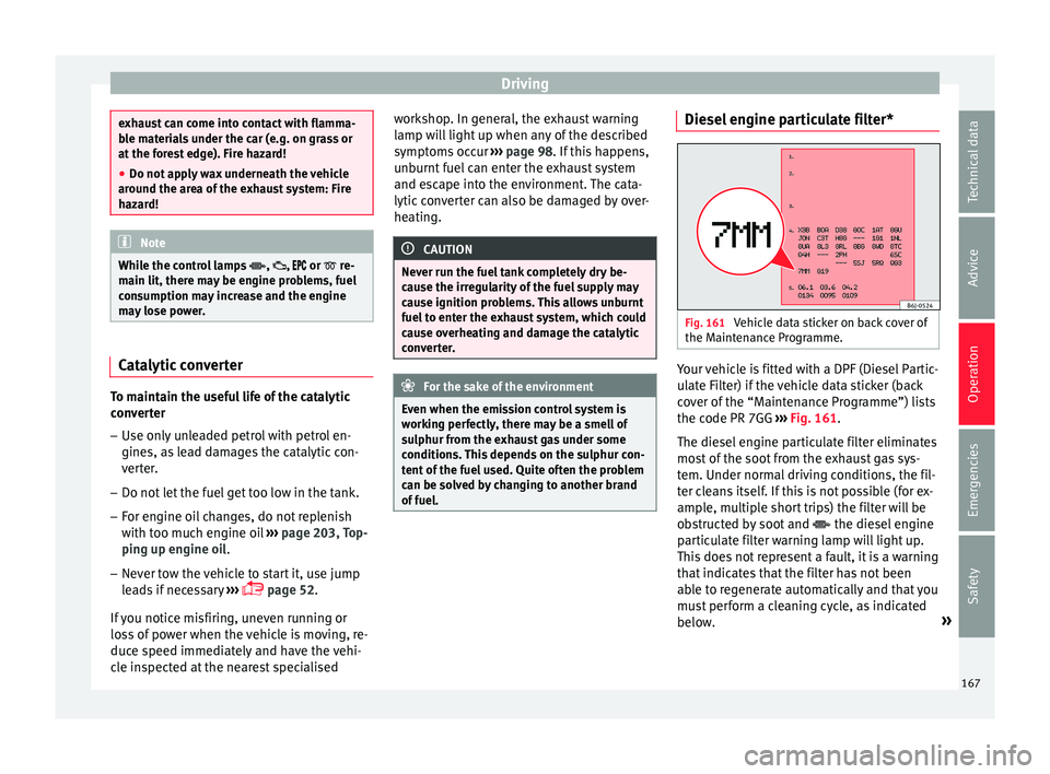
Fig. 161
Vehicle data sticker on back cover of
the M aint
en
ance Programme. Your vehicle is fitted with a DPF (Diesel Partic-
u
l
at
e Filter) if the vehicle data sticker (back
cover of the “Maintenance Programme”) lists
the code PR 7GG ››› Fig. 161.
The diesel engine particulate filter eliminates
most of the soot from the exhaust gas sys-
tem. Under normal driving conditions, the fil-
ter cleans itself. If this is not possible (for ex-
ample, multiple short trips) the filter will be
obstructed by soot and the diesel engine
particulate filter warning lamp will light up.
This does not represent a fault, it is a warning
that indicates that the filter has not been
able to regenerate automatically and that you
must perform a cleaning cycle, as indicated
below. »
167
Technical data
Advice
Operation
Emergencies
Safety
Page 170 of 248
Operation
Accumulation of soot in the diesel engine
p ar
tic
ulate filter*
If the control lamp lights up you should
help the filter clean itself by driving in the ap-
propriate manner.
To do this, drive about 15 minutes in fourth
or fifth gear (automatic gearbox: S gear
range) at a minimum speed of 60 km/h
(37 mph), with the engine running at approxi-
mately 2,000 rpm. In this way, the soot build
up in the filter is burned. When cleaning is
successful, the control lamp turns off.
If the lamp does not turn off, or the three
lamps turn on (particulate filter , fault in
the emission control system and glow
plugs ), drive the vehicle to a specialised
workshop and have the fault repaired at the
earliest opportunity. WARNING
Always drive according to the road weather
condition s, the t
errain and traffic. Driving rec-
ommendations should never lead to illegal
manoeuvres in surrounding traffic. CAUTION
● Your v
ehicle is not designed to use biodie-
sel fuel. Never, under any circumstances re-
fuel with biodiesel. The use of biodiesel fuel
could damage the engine and the fuel sys-
tem. The addition of biodiesel to diesel by
the diesel producer in accordance with stand- ard EN 590 is authorised and will not cause
dam
ag
e to the engine or the fuel system.
● Using diesel fuel with a high sulphur con-
tent m
ay significantly reduce the useful life of
the diesel particulate filter. Your Technical
Service will be able to tell you which coun-
tries have diesel with a high sulphur content. Engine management*
This warning lamp monitors the engine man-
agement
sy
stem for petrol engines.
The warning lamp (Electronic Power Con-
trol) lights up when the ignition is switched
on while system operation is being verified. It
should go out once the engine is started.
If there is a fault in the electronic engine
management system while you are driving,
this warning lamp will light up. Take the vehi-
cle to a specialised workshop as soon as
possible and have the engine checked.
Emission control system* Control lamp
fla
she
s:
When there is misfiring that can damage the
catalytic converter. Reduce speed and drive
carefully to the nearest specialised workshop
to have the engine checked. The control lamp
lights up:
If
a fault has developed during driving which
has reduced the quality of the exhaust gas
(e.g. lambda probe fault). Reduce speed and
drive carefully to the nearest specialised
workshop to have the engine checked.
Engine pre-heating/fault system* The warning lamp lights up to show that the
glow p
lug
s are preheating the diesel engine.
The control lamp lights up
If the control lamp lights up when the en-
gine is started it means that the glow plugs
are preheating. The engine can be started
straight away when the lamp switches off.
Control lamp flashes
If a fault develops in the engine management
system while you are driving, the glow plug
system lamp will flash . Take the vehicle to
a specialised workshop as soon as possible
and have the engine checked.
168