2016 Seat Ibiza SC heating
[x] Cancel search: heatingPage 100 of 248

Operation
●
Addition a
l lights and other accessories in
front of the air inlet reduce the cooling effect
of the coolant. At high outside temperatures
and high engine loads, there is a risk of the
engine overheating.
● The front spoiler also ensures proper distri-
bution of the c
ooling air when the vehicle is
moving. If the spoiler is damaged this can re-
duce the cooling effect, which could cause
the engine to overheat. Seek specialist assis-
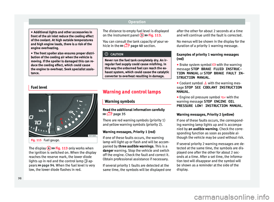
tance. Fuel level
Fig. 115
Fuel gauge. The display
6
› ›
› Fig. 113
only works when
the ignition is switched on. When the display
reaches the reserve mark, the lower diode
lights up in red and the control lamp ap-
pears ››› page 94. When the fuel level is very
low, the lower diode flashes in red. The distance to empty fuel level is displayed
on the instrument
panel 3
› ››
Fig. 113
.
Y
ou can consult the tank capacity of your ve-
hicle in the ›››
page 40 section. CAUTION
Never run the fuel tank completely dry. An ir-
re gu
lar fuel supply could cause misfiring. In
this way the unburned fuel can reach the ex-
haust system, which could cause the catalytic
converter to overheat resulting in damage. Warning and control lamps
W arnin
g symbo
ls Read the additional information carefully
› ›
›
page 35
There are red warning symbols (priority 1)
and yellow warning symbols (priority 2).
Warning messages, Priority 1 (red)
If one of these faults occurs, the warning
lamp will light up or flash and will be accom-
panied by three audible warnings. This is a
danger warning. Stop the vehicle and switch
off the engine. Check the fault and correct it.
Obtain professional assistance if necessary.
If several priority 1 faults are detected at the
same time, the symbols will be displayed one after the other for about 2 seconds at a time
and wil
l continue until the fault is corrected.
No menus will be shown in the display for the
duration of a priority 1 warning message.
Examples of priority 1 warning messages
(red)
● Brake system symbol with the warnin
g
message STOP BRAKE FLUID INSTRUC-
TION MANUAL or STOP BRAKE FAULT IN-
STRUCTION MANUAL .
● Coolant symbol with the warnin
g mes-
sage STOP SEE COOLANT INSTRUCTION
MANUAL .
● Engine oil pressure symbol with the
warnin
g message STOP ENGINE OIL
PRESSURE LOW! INSTRUCTION MANUAL .
Warning messages, Priority 2 (yellow)
If one of these faults occurs, the correspond-
ing warning lamp lights up and is accompa-
nied by an audible warning. Check the corre-
sponding function as soon as possible al-
though the vehicle may be used without risk.
If several priority 2 warning messages are de-
tected at the same time, the symbols are dis-
played one after the other for about 2 sec-
onds at a time. After a set time, the informa-
tion text will disappear and the symbol will
be shown as a reminder at the side of the
display.
98
Page 125 of 248

Lights and visibility
Visibility He at
ed r
ear window Fig. 128
Centre console: heated rear window
sw it
c
h. The heated rear window only works when the
en
gine i
s
running. When it is switched on, a
lamp lights up on the switch.
After approximately 8 minutes, the heating
device of the rear window switches off auto-
matically. For the sake of the environment
The heated rear window should be switched
off a s
soon as the glass is demisted. By sav-
ing electrical power you can also save fuel. Note
To avoid possible damage to the battery, an
autom atic
temporary disconnection of this function is possible, coming back on when
norma
l
operating conditions are re-establish-
ed. Sun visors
Fig. 129
Sun visor on the driver side. The sun visors for the driver and the front
p
a
s
senger can be pulled out of their central
supports and turned towards the doors in the
direction of the arrow ››› Fig. 129. Never pull
them downwards.
The driver sun visor has compartments for
cards, and the passenger sun visor has a
vanity mirror with a cover*. Note
Incorrect use of the sun visor (e.g. pulling
them down w
ards once they are open) may re-
sult in broken hinges. This damage is not cov-
ered by the vehicle warranty. Windscreen wiper and rear win-
do
w w
iper sy
stems
Control lamp*
It lights up
Windscreen wiper fluid level too low
This serves as a reminder to fill up the reser-
voir at
the e
arliest opportunity ››› page 207.
Windscreen wipers Read the additional information carefully
› ›
›
page 23 WARNING
● Worn and dir ty
wiper blades reduce visibili-
ty and safety levels while driving.
● In cold conditions you should not use the
wash/w
ipe system unless you have warmed
the windscreen with the heating and ventila-
tion system. The windscreen washer fluid
could otherwise freeze on the windscreen and
obscure your view of the road.
● Always note the corresponding warnings
›››
page 54. » 123
Technical data
Advice
Operation
Emergencies
Safety
Page 128 of 248

Operation
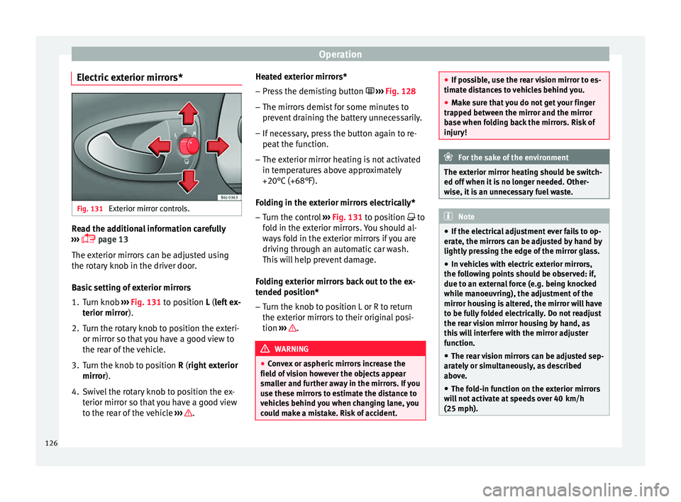
Electric exterior mirrors* Fig. 131
Exterior mirror controls. Read the additional information carefully
› ›
›
page 13
The exterior mirrors can be adjusted using
the rotary knob in the driver door.
Basic setting of exterior mirrors
1. Turn knob ››› Fig. 131
to position L (left ex-
terior mirror).
2. Turn the rotary knob to position the exteri- or mirror so that
you have a good view to
the rear of the vehicle.
3. Turn the knob to position R (right ext
erior
mirror).
4. Swivel the rotary knob to position the ex- terior mirror so th
at you have a good view
to the rear of the vehicle ››› .Heated exterior mirrors*
– Press the demisting button › ›
›
Fig. 128
– The mirrors demist for some minutes to
prevent
draining the battery unnecessarily.
– If necessary, press the button again to re-
peat the f
unction.
– The exterior mirror heating is not activated
in temperat
ures above approximately
+20°C (+68°F).
Folding in the exterior mirrors electrically* – Turn the control ›››
Fig. 131 to position to
fold in the exterior mirrors. You should al-
ways fold in the exterior mirrors if you are
driving through an automatic car wash.
This will help prevent damage.
Folding exterior mirrors back out to the ex-
tended position* – Turn the knob to position L or R to return
the exterior mirr
ors to their original posi-
tion ››› .
WARNING
● Con v
ex or aspheric mirrors increase the
field of vision however the objects appear
smaller and further away in the mirrors. If you
use these mirrors to estimate the distance to
vehicles behind you when changing lane, you
could make a mistake. Risk of accident. ●
If po s
sible, use the rear vision mirror to es-
timate distances to vehicles behind you.
● Make sure that you do not get your finger
trapped betw
een the mirror and the mirror
base when folding back the mirrors. Risk of
injury! For the sake of the environment
The exterior mirror heating should be switch-
ed off when it i
s no longer needed. Other-
wise, it is an unnecessary fuel waste. Note
● If the el ectric
al adjustment ever fails to op-
erate, the mirrors can be adjusted by hand by
lightly pressing the edge of the mirror glass.
● In vehicles with electric exterior mirrors,
the fol
lowing points should be observed: if,
due to an external force (e.g. being knocked
while manoeuvring), the adjustment of the
mirror housing is altered, the mirror will have
to be fully folded electrically. Do not readjust
the rear vision mirror housing by hand, as
this will interfere with the mirror adjuster
function.
● The rear vision mirrors can be adjusted sep-
arately
or simultaneously, as described
above.
● The fold-in function on the exterior mirrors
wil
l not activate at speeds over 40 km/h
(25 mph). 126
Page 130 of 248

Operation
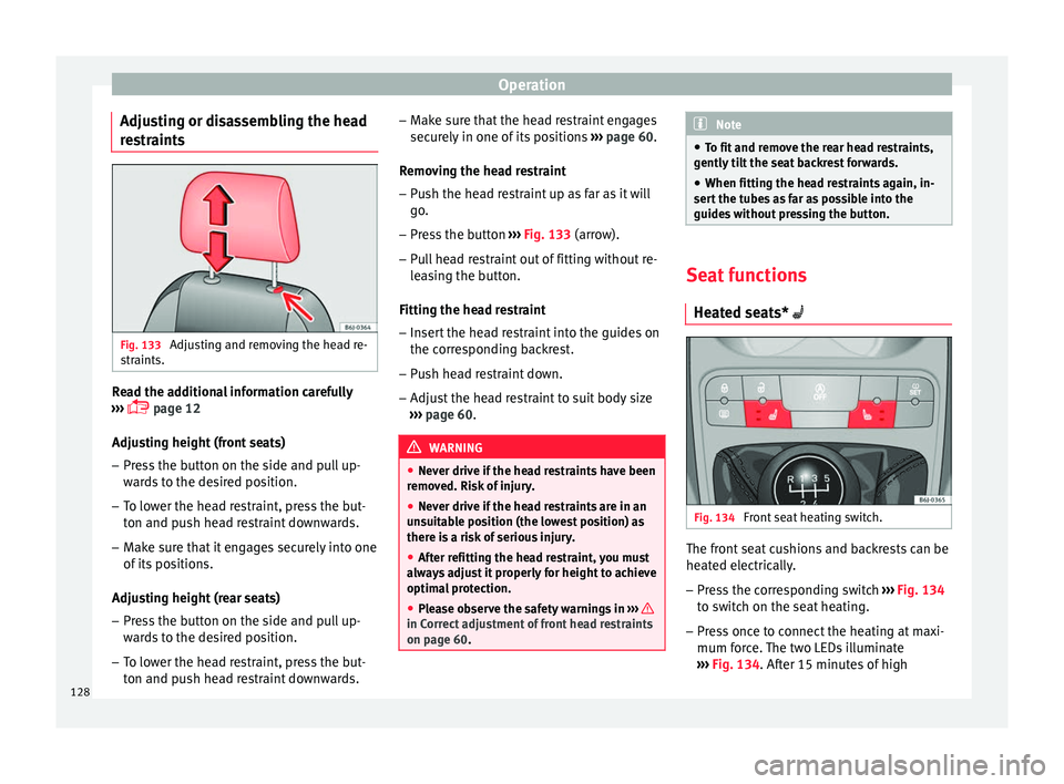
Adjusting or disassembling the head
r e
s
traints Fig. 133
Adjusting and removing the head re-
s tr
aints. Read the additional information carefully
› ›
›
page 12
Adjusting height (front seats)
– Press the button on the side and pull up-
ward
s to the desired position.
– To lower the head restraint, press the but-
ton and pu
sh head restraint downwards.
– Make sure that it engages securely into one
of its po
sitions.
Adjusting height (rear seats)
– Press the button on the side and pull up-
ward
s to the desired position.
– To lower the head restraint, press the but-
ton and pu
sh head restraint downwards. –
Make s
ure that the head restraint engages
securely in one of its positions ››› page 60.
Removing the head restraint – Push the head restraint up as far as it will
go.
– Pr
ess the button ›››
Fig. 133 (arrow).
– Pull head restraint out of fitting without re-
lea
sing the button.
Fitting the head restraint
– Insert the head restraint into the guides on
the corre
sponding backrest.
– Push head restraint down.
– Adjust the head restraint to suit body size
›››
page 60. WARNING
● Never driv e if
the head restraints have been
removed. Risk of injury.
● Never drive if the head restraints are in an
uns
uitable position (the lowest position) as
there is a risk of serious injury.
● After refitting the head restraint, you must
alwa
ys adjust it properly for height to achieve
optimal protection.
● Please observe the safety warnings in ›››
in Correct adjustment of front head restraints
on pag
e 60
. Note
● To fit and r
emove the rear head restraints,
gently tilt the seat backrest forwards.
● When fitting the head restraints again, in-
sert the t
ubes as far as possible into the
guides without pressing the button. Seat functions
Heat ed se
ats* Fig. 134
Front seat heating switch. The front seat cushions and backrests can be
he
at
ed el
ectrically.
– Press the corresponding switch ›››
Fig. 134
to switch on the seat heating.
– Press once to connect the heating at maxi-
mum forc
e. The two LEDs illuminate
››› Fig. 134. After 15 minutes of high
128
Page 131 of 248

Seats and head restraints
intensity, the upper LED goes out, the sys-
t em i
s
deactivated for 2 minutes and is
then reactivated at low intensity (the lower
LED remains on permanently).
– Press the switch again to set the heating to
minimum forc
e. (The lower LED lights up).
– To disconnect the heating, press the switch
again. CAUTION
To avoid damaging the heating elements,
pl e
ase do not kneel on the seat or apply
sharp pressure at a single point to the seat
cushion and backrest. Note
The seats are only heated electrically when
the engine i s
running. Folding down the back seat
Fig. 135
Folding up the rear seat cushion. Fig. 136
Button for unlocking the rear back-
r e
s
t. Folding seat down
– Remove the head restraint ››
›
page 128.
– Pull the front edge of the seat cushion
›››
Fig. 135 1 upwards in the direction of
the arr o
w
. –
Lift the c
ushion 2 forwards in the direc-
tion of the arr
o
w.
– Pull the release button ›››
Fig. 136 in the di-
rection of the arrow and fold the backrest forwards.
– Insert the head restraints in the spaces on
the rear of
the seat cushion which are visi-
ble when the seat cushion is lowered.
Folding seat forward
– Remove the head restraints from the
spac
es in the seat cushion.
– Lift the backrest, and before securing it, re-
plac
e the head restraints in the seat cush-
ion, and then click the seat correctly onto
the locking rails.
– Once the backrest is locked, pull on the
central
seat belt or directly on the backrest
to check that the backrest has properly en-
gaged in position.
– Check that the position lever is in neutral
position.
– L
ower the cushion and push it backwards
below the seat
belt buckles.
– Press the front part of the cushion down-
ward
s.
On split rear seats*, the backrest and cush-
ion can be lowered and raised respectively in
two sections. »
129
Technical data
Advice
Operation
Emergencies
Safety
Page 136 of 248

Operation
vehicle may change, leading to accidents,
injuries
and d
amage to the vehicle.
● Please note that the centre of gravity may
shift when tr
ansporting heavy objects; this
may affect vehicle handling and lead to an ac-
cident. Therefore, it is essential to adjust
your speed and driving style accordingly, to
avoid accidents.
● Never leave your vehicle unattended, espe-
cia
lly when the rear lid is open. Children
could climb into the luggage compartment,
closing the door behind them; they will be
trapped and run the risk of death.
● Never allow children to play in or around
the vehic
le. Close and lock all the doors and
rear lid when you leave the vehicle. Before
you lock the vehicle, make sure that there are
no adults or children in the vehicle.
● Please observe the notes on the ›››
page 56. CAUTION
Hard objects on the rear shelf could chafe
again s
t the wires of the heating element in
the heated rear window and cause damage. Note
● The tyr e pr
essure must be adjusted accord-
ing to the load. When necessary check the
tyre pressures on the label located on the in-
side fuel tank flap ››› page 210.
● Air circulation in the vehicle helps reduce
foggin
g of the windows. Used air escapes through ventilation slits in the side trim of
the lugg
ag
e compartment. Ensure that the
ventilation slots are never covered.
● Straps for securing the load to the fasten-
ing ring
s* are commercially available from ac-
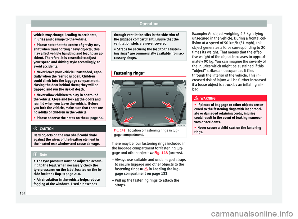
cessory shops. Fastening rings*
Fig. 148
Location of fastening rings in lug-
g ag
e c
ompartment. There may be four fastening rings included in
the lug
g
ag
e compartment for fastening lug-
gage and other objects ››› Fig. 148 (arrows).
– Always use suitable and undamaged straps
to secur
e luggage and other objects to the
fastening rings ››› in Loading the lug-
g ag
e c
ompartment on page 133.
– Pull up the fastening rings to attach the
strap
s. Example: An object weighing 4.5 kg is lying
unsec
ured in the vehicle. During a frontal col-
lision at a speed of 50 km/h (31 mph), this
object generates a force corresponding to 20
times its weight. That means that the effec-
tive weight of the object increases to approxi-
mately 90 kg. You can imagine the severity of
the injuries which might be sustained if this
“object” strikes an occupant as it flies
through the interior of the vehicle. This in-
creased risk of injury will be further increased
if a loose object is struck by an inflating air-
bag. WARNING
● If piec e
s of baggage or other objects are se-
cured to the fastening rings with inappropri-
ate or damaged retaining cords, injuries
could result in the event of braking manoeu-
vres or accidents.
● Never secure a child seat on the fastening
rings. 134
Page 139 of 248

Air conditioning
Air conditioning
He atin
g,
ventilation and cool-
ing
General notes Read the additional information carefully
›› ›
page 39
Pollution filter
The pollution filter (a combined particulate
filter and active carbon filter) serves as a bar-
rier against impurities in the outside air, in-
cluding dust and pollen.
For the climate control system to work with
maximum efficiency, the pollution filter must
be replaced at the specified intervals in the
Maintenance Programme.
If the filter loses efficiency prematurely due
to use in areas reaching very high pollution
levels, the pollen filter must be changed
more frequently than stated in the Service
Schedule. WARNING
Reduced visibility through the windows in-
cr e
ases the risk of serious accidents.
● Always ensure that all windows are free of
ice and sno
w, and that they are not fogged, so as to maintain good visibility of everything
outs
ide.
● The m
aximum heat output required to de-
fros
t windows as quickly as possible is only
available when the engine has reached its
normal running temperature. Only drive when
you have good visibility.
● Always ensure that you use the heating
syst
em, fresh air system, air conditioner and
the heated rear window to maintain good visi-
bility to the outside.
● Never leave the air recirculation on for a
long period of time. If
the cooling system is
switched off and air recirculation mode
switched on, the windows can mist over very
quickly, considerably limiting visibility.
● Switch air recirculation mode off when it is
not requir
ed. WARNING
Stuffy or used air will increase fatigue and re-
duce driv er c
oncentration possibly resulting
in a serious accident.
● Never leave the fresh air fan turned off or
use the air rec
irculation for long periods of
time; the air in the vehicle interior will not be
refreshed. CAUTION
● If y
ou suspect that the air conditioner is
damaged, switch it off with the A/C button to prevent further damage and have it checked
by
a s
pecialised workshop.
● Repairs to the air conditioner require spe-
cia
list knowledge and special tools. There-
fore, we recommend you to take the vehicle
to a specialised workshop. Note
● If the humidity and t
emperature outside the
vehicle are high, condensation can drip off
the evaporator in the cooling system and
form a pool underneath the vehicle. This is
normal and does not indicate a leak.
● Keep the air intake slots in front of the
winds
creen free of snow, ice and leaves to en-
sure heating and cooling are not impaired,
and to prevent the windows from misting
over.
● The air from the vents flows through the ve-
hicle int
erior and is extracted by slots in the
luggage compartment designed for this pur-
pose. Therefore, you should avoid obstruct-
ing these slots with any kind of object.
● The air conditioner operates most effective-
ly with the w
indows and the sliding/tilting
sunroof* closed. However, if the temperature
inside the vehicle is excessive because of the
sun, the air inside can be cooled faster by
opening the windows for a short time.
● Do not smoke while air recirculation mode
is on, a
s smoke drawn into the air condition-
ing system leaves residue on the evaporator,
producing a permanent unpleasant odour. » 137
Technical data
Advice
Operation
Emergencies
Safety
Page 141 of 248

Air conditioning
Air distributionSymbol ››› page 139
CMain air output through out-
lets
1, 2
5
1, 2, 5
3, 4
Outlets
3 and
4 can be closed or opened
separ at
ely using the slats and the air flow di-
rected as required.
Heating and fresh air
Contr o
ls Fig. 153
Heating controls on the dash panel. ●
Use t
urn c
ontrols A ,
B and
C
› ››
Fig. 153
t o a
djust the temperature, blower speed and
air distribution.
● Press the D button to switch air recircula-
tion mode on or off .
When the f
unction is ac-
tivated, a warning light on the button is
turned on.
Temperature
Switch A adjusts temperature. The desired
t emper
at
ure inside the vehicle cannot be
lower than the ambient temperature. Maxi-
mum heat output, which is needed to defrost
the windows quickly, is only available when
the engine has reached its operating temper-
ature.
Blower
The air flow can be set at four speeds with
switch B . The blower should always be set
at the lo
w
est speed when driving slowly.
Air distribution
Control C for setting the flow of air in the re-
quir ed dir
ection.
– Air distribution towards the windscreen
in order to demist. For safety reasons, it is
not recommended to switch air recirculation
on.
– Air distribution to upper body.
– Air distribution to footwell – Air distribution to the windscreen and
the footw
ell. WARNING
● For y
our safety, the windows should never
be fogged up or covered with snow or ice.
This is essential to ensure good visibility.
Please familiarise yourself with the correct
operation of the heating and ventilation sys-
tem, including the demist/defrost functions
for the windows. Note
● Ple a
se consider the general notes
››› page 137. Air recirculation
Air recirculation prevents unpleasant smells
fr
om ent
erin
g the interior.
Connecting the recirculation
In any position of rotary switch C except
th a
w:
● Pr
ess button D
› ›
›
Fig. 153 and the lamp in
the button will illuminate.
Disconnecting the recirculation
● If the lamp is on, press button D and the
l amp w
i
ll go off, indicating that the entry of
outside air has been activated. »
139
Technical data
Advice
Operation
Emergencies
Safety