Page 296 of 520
294
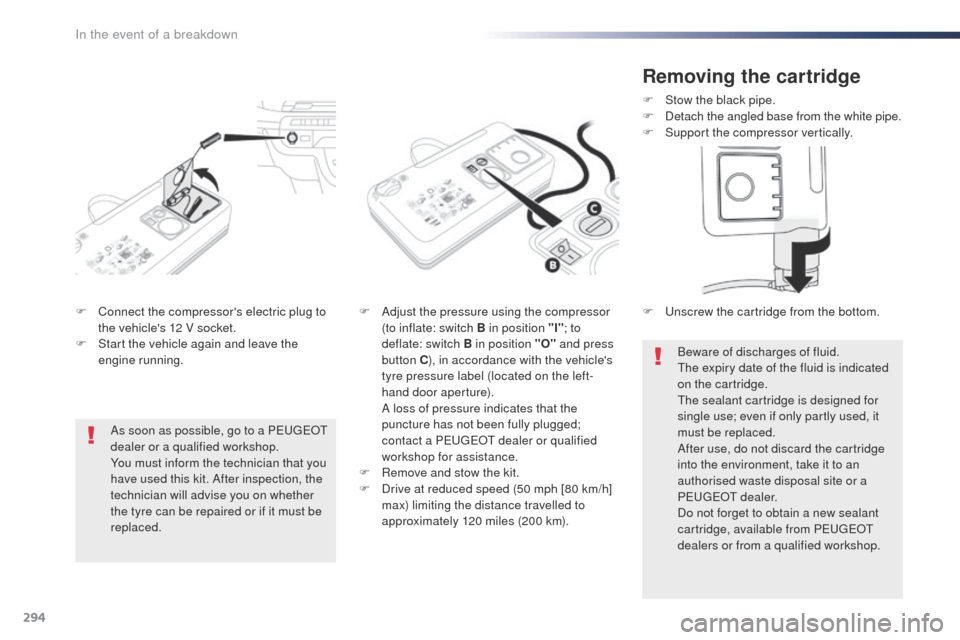
F Connect the compressor's electric plug to the vehicle's 12 V socket.
F
S
tart the vehicle again and leave the
engine running. F
A djust the pressure using the compressor
(to inflate: switch B in position "I" ; to
deflate: switch B in position "O" and press
button C ), in accordance with the vehicle's
tyre pressure label (located on the left-
hand door aperture).
A l
oss of pressure indicates that the
puncture has not been fully plugged;
contact a P
e
ugeot dealer or qualified
workshop for assistance.
F
R
emove and stow the kit.
F
D
rive at reduced speed (50 mph [80 km/h]
max) limiting the distance travelled to
approximately 120 miles (200 km).
As soon as possible, go to a P
e
ugeot
dealer or a qualified workshop.
You must inform the technician that you
have used this kit. After inspection, the
technician will advise you on whether
the tyre can be repaired or if it must be
replaced.
Removing the cartridge
F Stow the black pipe.
F D etach the angled base from the white pipe.
F
S
upport the compressor vertically.
Beware of discharges of fluid.
th
e expiry date of the fluid is indicated
on the cartridge.
th
e sealant cartridge is designed for
single use; even if only partly used, it
must be replaced.
After use, do not discard the cartridge
into the environment, take it to an
authorised waste disposal site or a
P
e
ugeot
d
ealer.
Do not forget to obtain a new sealant
cartridge, available from P
e
ugeot
dealers or from a qualified workshop.
F
u
n
screw the cartridge from the bottom.
In the event of a breakdown
Page 297 of 520
295
Checking / adjusting tyre
pressures
You can also use the compressor without
injecting any product, to check and if necessary
adjust your tyre pressures.F
t
u
rn the selector A to the "Air"
position. F
C
onnect the compressor's electrical
connector to the vehicle's 12 V socket.
F
S
tart the vehicle and let the engine run.
F
A
djust the pressure using the compressor
(to inflate: switch B in position "I" ; to
deflate: switch B in position "O" and press
button C ), according to the vehicle's tyre
pressure label.
F
R
emove the kit then stow it.Should the pressure of one or more
tyres be adjusted, it is necessary to
reinitialise the under-inflation detection
system.
For more information on Under-
inflation detection
, refer to the
corresponding section.
F
u
n
coil the black pipe H fully.
F
C
onnect the black pipe to the tyre valve.
8
In the event of a breakdown
Page 298 of 520
296
Changing a wheel
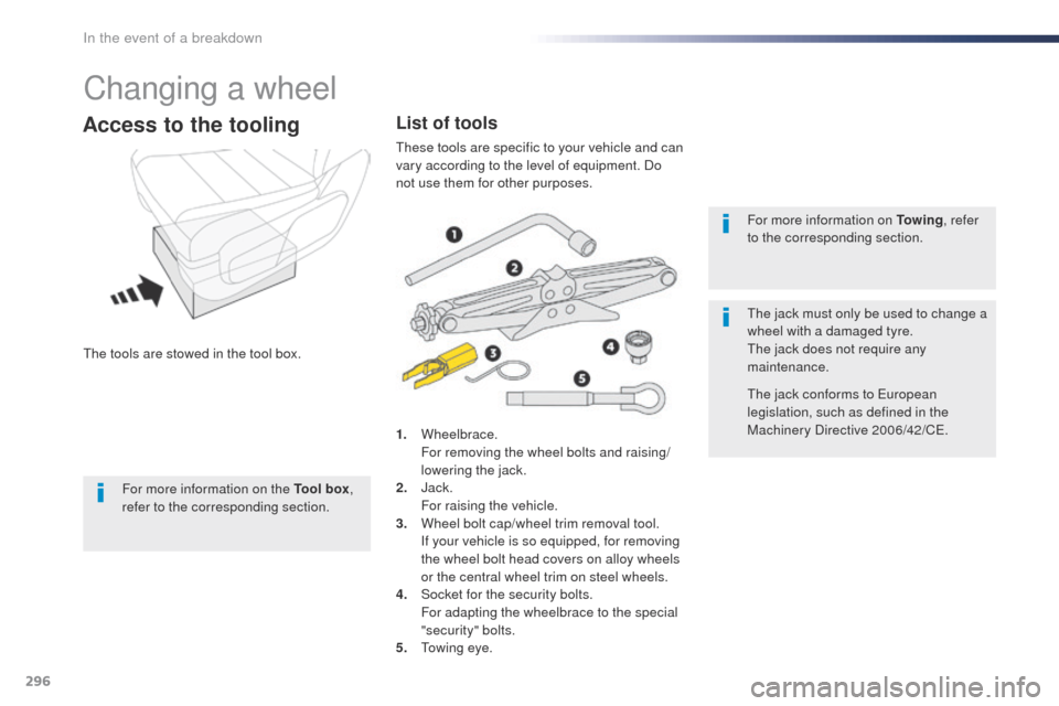
the tools are stowed in the tool box.
Access to the tooling
1. Wheelbrace. F
or removing the wheel bolts and raising/
lowering the jack.
2.
J
ack.
F
or raising the vehicle.
3.
W
heel bolt cap/wheel trim removal tool.
I
f your vehicle is so equipped, for removing
the wheel bolt head covers on alloy wheels
or the central wheel trim on steel wheels.
4.
S
ocket for the security bolts.
F
or adapting the wheelbrace to the special
"security" bolts.
5.
t
o
wing eye. For more information on To w i n g
, refer
to the corresponding section.
th
e jack must only be used to change a
wheel with a damaged tyre.
th
e jack does not require any
maintenance.
th
e jack conforms to e
u
ropean
legislation, such as defined in the
Machinery Directive 2006/42/Ce.
List of tools
these tools are specific to your vehicle and can
vary according to the level of equipment. Do
not use them for other purposes.
For more information on the Tool box ,
refer to the corresponding section.
In the event of a breakdown
Page 299 of 520
297
F Access to the spare wheel is from the rear.
F op en the side-hinged rear doors or the
tailgate, according to the configuration of
your vehicle. F
A
ccess the carrier bolt, located on the rear
door sill.
F t
u
rn the bolt anti-clockwise using the
wheelbrace (about 14 turns) until the
carrier is low enough to allow the carrier
hook to be disengaged.
Access to the spare wheel
F If your vehicle is fitted with a towbar, raise the rear of the vehicle using the jack (must
be at jacking point B ) to allow sufficient
space to remove the spare wheel.
Removing
to avoid any unwanted opening of the
electric side door(s), deactivate the
" Hands-Free Access " function in the
vehicle configuration menu.
For more information on the Hands-
free sliding side door , refer to the
corresponding section.
8
In the event of a breakdown
Page 304 of 520
302
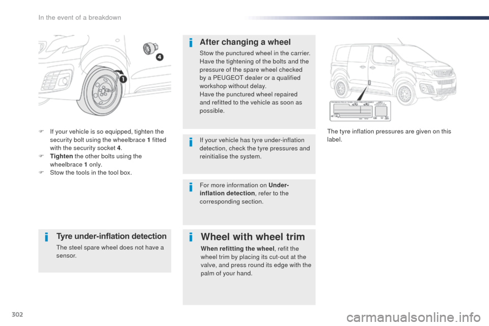
F If your vehicle is so equipped, tighten the security bolt using the wheelbrace 1 fitted
with the security socket 4 .
F
T
ighten the other bolts using the
wheelbrace 1 o n l y.
F
S
tow the tools in the tool box.th e tyre inflation pressures are given on this
label.
After changing a wheel
Stow the punctured wheel in the carrier.
Have the tightening of the bolts and the
pressure of the spare wheel checked
by a P
e
ugeot dealer or a qualified
workshop without delay.
Have the punctured wheel repaired
and refitted to the vehicle as soon as
possible.
If your vehicle has tyre under-inflation
detection, check the tyre pressures and
reinitialise the system.
Tyre under-inflation detection
the steel spare wheel does not have a
sensor.
Wheel with wheel trim
When refitting the wheel , refit the
wheel trim by placing its cut-out at the
valve, and press round its edge with the
palm of your hand.
For more information on Under-
inflation detection
, refer to the
corresponding section.
In the event of a breakdown
Page 307 of 520
305
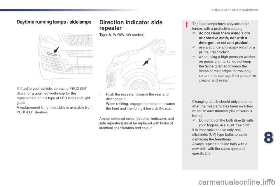
Direction indicator side
repeater
Ty p e A, W Y5W-5W (amber)
Daytime running lamps / sidelamps
If fitted to your vehicle, contact a Pe ugeot
dealer or a qualified workshop for the
replacement of this type of L
eD l
amp and light
guide.
A replacement kit for the L
eD
s is available from
P
e
ugeot
d
ealers.
th
e headlamps have polycarbonate
lenses with a protective coating:
F
d
o not clean them using a dr y
or abrasive cloth, nor with a
detergent or solvent product,
F
u
se a sponge and soapy water or a
pH neutral product,
F
w
hen using a high pressure washer
on persistent marks, do not keep
the lance directed towards the
lamps or their edges for too long,
so as not to damage their protective
coating and seals.
Changing a bulb should only be done
after the headlamp has been switched
off for several minutes (risk of serious
burns).
F
D
o not touch the bulb directly with
your fingers, use a lint-free cloth.
It is imperative to use only anti-
ultraviolet (
uV
) type bulbs to avoid
damaging the headlamp.
Always replace a failed bulb with a
new bulb with the same type and
specification.
-
P
ush the repeater towards the rear and
disengage it.
-
W
hen refitting, engage the repeater towards
the front and then bring it towards the rear.
Amber coloured bulbs (direction indicators and
side repeaters) must be replaced with bulbs of
identical specification and colour.
8
In the event of a breakdown
Page 313 of 520
311
Number plate lamps
(side-hinged doors)
Ty p e A, W5W-5W
F
R
emove the plastic cover using a small
screwdriver.
F
u
s
ing a screwdriver through the aperture,
push the lamp towards the outside.
F
D
isconnect the electrical connector.
F
R
emove the lamp.
F
t
u
rn the bulb holder a quarter turn anti-
clockwise.
F
C
hange the failed bulb.
to r
efit, press on the lamp to clip it in place.
Third brake lamp
(side-hinged doors)
Ty p e A , W5W-5W
to r
efit, press on the lens to clip it in place.
F
o
p
en the left-hand rear door. F
I
nsert a thin screwdriver into one of the cut-
outs in the lens.
F
P
ush it outwards to unclip it.
F
R
emove the lens.
F
C
hange the failed bulb.
8
In the event of a breakdown
Page 315 of 520
313
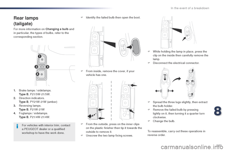
Rear lamps
(tailgate)
For more information on Changing a bulb and
in particular, the types of bulbs, refer to the
corresponding section.
F
W
hile holding the lamp in place, press the
clip on the inside then carefully remove the
lamp.
F
D
isconnect the electrical connector.
F
I
dentify the failed bulb then open the boot.
For vehicles with interior trim, contact
a P
e
ugeot dealer or a qualified
workshop to have the work done.
1.
B
rake lamps / sidelamps.
Ty
p e B, P21/5W-21/5W.
2.
D
irection indicators.
Ty
p e B, PY21W-21W (amber)
3.
R
eversing lamps.
Ty
p e B, P21W-21W
4.
F
oglamps / sidelamps.
Ty
p e B, P21/4W-21/4W. F
F
rom inside, remove the cover, if your
vehicle has one.
F
F
rom the outside, press on the inner clips
on the plastic finisher then tip it towards the
outside to remove it.
F
u
n
screw the two lamp fixing screws.F
S
pread the three lugs slightly, then extract
the bulb holder.
F
R
emove the failed bulb by pressing
lightly on it, then turning it a quarter turn
clockwise.
F
C
hange the bulb.
to r
eassemble, carry out these operations in
reverse order.
8
In the event of a breakdown