Page 231 of 364

229
508_en_Chap08_en-cas-de-pannes_ed01-2016
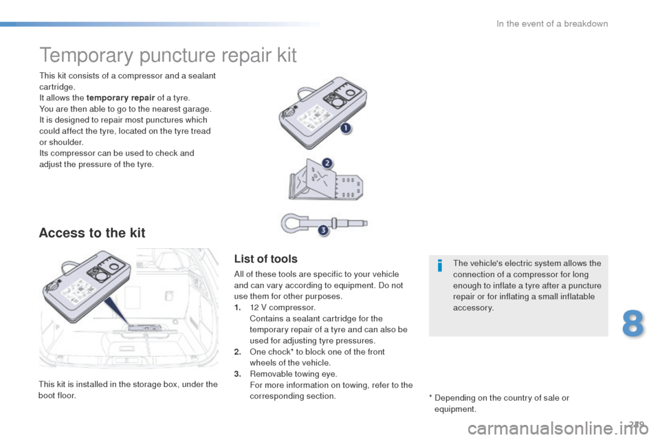
this kit is installed in the storage box, under the
boot floor.
th
is kit consists of a compressor and a sealant
cartridge.
It allows the temporary repair of a tyre.
You are then able to go to the nearest garage.
It is designed to repair most punctures which
could affect the tyre, located on the tyre tread
or shoulder.
Its compressor can be used to check and
adjust the pressure of the tyre.
temporary puncture repair kit
Access to the kit
List of tools
All of these tools are specific to your vehicle
and can vary according to equipment. Do not
use them for other purposes.
1.
1
2 V compressor.
C
ontains a sealant cartridge for the
temporary repair of a tyre and can also be
used for adjusting tyre pressures.
2.
O
ne chock* to block one of the front
wheels of the vehicle.
3.
R
emovable towing eye.
F
or more information on towing, refer to the
corresponding section. *
D
epending on the country of sale or
equipment.th e vehicle's electric system allows the
connection of a compressor for long
enough to inflate a tyre after a puncture
repair or for inflating a small inflatable
accessory.
8
In the event of a breakdown
Page 237 of 364

235
508_en_Chap08_en-cas-de-pannes_ed01-2016
Spare wheel
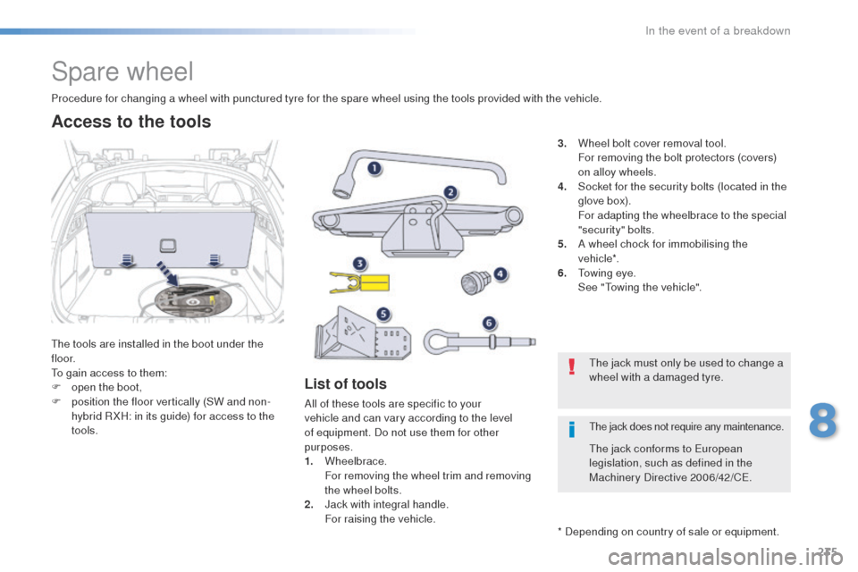
the tools are installed in the boot under the
f l o o r.
to g
ain access to them:
F
o
pen the boot,
F
p
osition the floor vertically (SW and non-
hybrid R XH: in its guide) for access to the
tools.
Procedure for changing a wheel with punctured tyre for the spare wheel using the tools provided with the vehicle.
List of tools
All of these tools are specific to your
vehicle and can vary according to the level
of equipment. Do not use them for other
purposes.
1.
Wheelbrace.
F
or removing the wheel trim and removing
the wheel bolts.
2.
J
ack with integral handle.
F
or raising the vehicle. 3.
W
heel bolt cover removal tool.
F
or removing the bolt protectors (covers)
on alloy wheels.
4.
S
ocket for the security bolts (located in the
glove box).
F
or adapting the wheelbrace to the special
"security" bolts.
5.
A w
heel chock for immobilising the
vehicle*.
6.
t
o
wing eye.
S
ee "
to
wing the vehicle".
Access to the tools
* Depending on country of sale or equipment.
th
e jack must only be used to change a
wheel with a damaged tyre.
th
e jack conforms to e
u
ropean
legislation, such as defined in the
Machinery Directive 2006/42/C
e.
the jack does not require any maintenance.
8
In the event of a breakdown
Page 238 of 364
236
508_en_Chap08_en-cas-de-pannes_ed01-2016
Wheel with wheel trim
When refitting the wheel, refit the trim
starting by placing its notch facing the
valve and press around its edge with
the palm of your hand.
th
e spare wheel is located in the boot under
t h e f l o o r.
Depending on the country of sale, the spare
wheel may be steel, alloy or of the "space-
saver" type.
Access to the spare wheel
Taking out the wheel
Depending on your vehicle's equipment, the
spare wheel is restrained either by a strap or
a securing nut A and bolt B . For the nut, the
procedure is given below. F
u
n
screw the (coloured) central nut.
F
R
aise the spare wheel towards you from
the rear.
F t
a
ke the wheel out of the boot.
In the event of a breakdown
Page 242 of 364

240
508_en_Chap08_en-cas-de-pannes_ed01-2016
Fitting a wheel
Fitting the "space-saver"
spare wheel
If your vehicle is fitted with alloy wheels,
when tightening the bolts on fitting, it
is normal to notice that the washers
do not come into contact with the
"space-saver" spare wheel. t
h
e wheel
is secured by the conical sur face of
each bolt.
After changing a wheel
to store the punctured wheel in the
boot correctly, first remove the central
c ove r.
When using the "space-saver" type
spare wheel, do not exceed 50 mph
(80
km/h).
Have the tightening of the bolts and the
pressure of the spare wheel checked
by a P
e
uge
Ot
dealer or a qualified
workshop without delay.
Have the punctured wheel repaired
and refitted to the vehicle as soon as
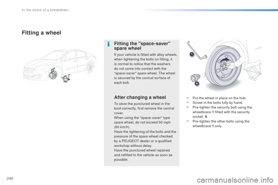
possible. F
P
ut the wheel in place on the hub.
F S crew in the bolts fully by hand.
F P re-tighten the security bolt using the
wheelbrace 1 fitted with the security
socket
4.
F
P
re-tighten the other bolts using the
wheelbrace 1 o n l y.
In the event of a breakdown
Page 247 of 364

245
508_en_Chap08_en-cas-de-pannes_ed01-2016
1. Brake lamps
( light emitting diodes - LEDs).
2.
Si
delamps
(
light emitting diodes - LEDs).
3.
D
irection indicators
(
PY21W amber).
4.
Fo
glamps
(
light-emitting diodes) /
R
eversing lamps (W16W).
Rear lamps (Saloon)
Direction indicators and reversing lamp
Direction indicators Reversing lamp
Light emitting diodes-LEDs
For replacement, contact a PeugeOt
dealer or qualified workshop. F
O
pen the boot, then the plastic cover.
F
R
emove the two lamp unit fixing nuts.
F e
x
tract the lamp unit carefully from the
outside.
F
D
isconnect the electrical connector.
F
S
pread the tabs and remove the bulb
h o l d e r.
F t
u
rn the bulb a quarter of a turn and pull it
out.
For reassembly, carry out these operations in
reverse order. -
R
emove the direction indicator bulb holder,
as described above.
- t
u
rn the bulb a quarter of a turn and
change it.to r eassemble, carry out these operations in
reverse order.
8
In the event of a breakdown
Page 248 of 364
246
508_en_Chap08_en-cas-de-pannes_ed01-2016
1. Brake lamps (light emitting diodes - LEDs).
2.
R
eversing lamps (W19W).
3.
D
irection indicators (PY21W amber).
4.
S
idelamps (light emitting diodes -
LEDs).
5.
F
oglamps (light emitting diodes - LEDs).
Rear lamps (SW and non-hybrid RXH)
F Open the boot then remove the access c ove r.
F
R
emove the sealing foam.
F
D
isconnect the lamp connector.
F
R
emove the lamp fixing nut.
Direction indicators
(on the wings)
F Carefully remove the lamp unit from
outside.
F
R
emove the sealing foam.
F
u
n
clip the bulb holder.
F
t
u
rn the bulb a quarter of a turn and pull
it
out.
For reassembly, carry out these operations in
reverse order.
Light emitting diodes-LEDs
For replacement, contact a Pe ugeOt
dealer or qualified workshop.
In the event of a breakdown
Page 253 of 364
251
508_en_Chap08_en-cas-de-pannes_ed01-2016
Fuse N° Rating
(A) Functions
F3 15Driver's electric window panel, 12 V socket for rear seats.
F4 1512 V socket in boot.
F5 30One-touch rear window.
F6 30One-touch front window.
F11 20
tr
ailer unit.
F12 20Audio amplifier.
F15 20Panoramic sunroof blind
(SW and non-hybrid R XH).
F16 5Driver's electric window switch panel.Fuses behind the glove box
8
In the event of a breakdown
Page 259 of 364

257
508_en_Chap08_en-cas-de-pannes_ed01-2016
Removing - refitting the battery*
* Valid only for Saloon, SW and non-hybrid
RHX.
th
is procedure allows you to safely remove the
battery when needed to change a failed bulb.
You can also call on a P
e
uge
Ot
dealer or a qualified workshop to carry
out this procedure.
Before removal
- Place the vehicle in a ventilated location, with free access and preferably on a level
sur face.
-
A
pply the parking brake.
-
P
ut the gear lever into neutral (position N
for an automatic gearbox).
-
I
f the vehicle has an alarm, leave the
bonnet open to avoid triggering the alarm.
-
L
eave at least one window open if in a
secure location, other wise lock all the
doors and the boot. -
I f the vehicle has a motorised tailgate,
it will not be possible to open it after
disconnecting the battery.
-
S
witch off the ignition and remove the key.
-
I
f the vehicle has Keyless e
n
try and
Starting, take the remote control at least
3
metres away from the vehicle.
-
W
ait about 4 minutes (or 12 minutes
with an automatic gearbox) before
disconnecting the battery.
8
In the event of a breakdown