Page 21 of 371

19
508 _en_Chap01_instrument-bord_ed01-2016
Warning lamps
When the engine is running or the vehicle is being driven, illumination of one of the following warning lamps indicates a fault which requires action on
the part of the driver.
Any fault resulting in the illumination of a warning lamp must be investigated further by reading the associated message in the instrument panel screen.
If you encounter any problems, contact a P
e
uge
Ot
dealer or a qualified workshop.
Warning / indicator lamp StateCause Action / Observations
STOP fixed, associated
with another warning
lamp, accompanied
by an audible signal
and a message in the
screen. Illumination of this warning lamp is
related to a serious fault with the
braking system, power steering, the
engine oil pressure or engine coolant
temperature or a major electrical
fault. Stop as soon as it is safe to do so as the engine may
cut out.
Park, switch off the ignition and call a P
e
uge
Ot
dealer or a qualified workshop.
1
Instruments
Page 110 of 371

108
508_en_Chap03_ergonomie-et-confort_ed01-2016
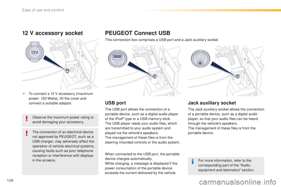
12 V accessory socket
Observe the maximum power rating to
avoid damaging your accessory.
th
e connection of an electrical device
not approved by P
e
uge
Ot, s
uch as a
uS
B charger, may adversely affect the
operation of vehicle electrical systems,
causing faults such as poor telephone
reception or inter ference with displays
in the screens.
PEUGEOT Connect USB
this connection box comprises a uS B port and a Jack auxiliary socket.
USB port
the uSB port allows the connection of a
portable device, such as a digital audio player
of the iPod
® type or a uS B memory stick.th
e
uS
B player reads your audio files, which
are transmitted to your audio system and
played via the vehicle's speakers.
th
e management of these files is from the
steering mounted controls or the audio system.
Jack auxiliary socket
the Jack auxiliary socket allows the connection
of a portable device, such as a digital audio
player, so that your audio files can be heard
through the vehicle's speakers.
th
e management of these files is from the
portable device.
For more information, refer to the
corresponding part of the "Audio
equipment and telematics" section.
When connected to the
u
S
B port, the portable
device charges automatically.
While charging, a message is displayed if the
power consumption of the portable device
exceeds the current delivered by the vehicle.
F
t
o c
onnect a 12 V accessory (maximum
power: 120 Watts), lift the cover and
connect a suitable adaptor.
ease of use and comfort
Page 182 of 371

180
508_en_Chap06_conduite_ed01-2016
Stop & Start
Operation
Going into engine STOP mode
the "ECO" indicator lamp comes
on in the instrument panel and the
engine goes into standby:
-
w
ith a manual gearbox, at speeds below
12 mph (20 km/h), or vehicle stationary
with the e-
tH
P 165 version, when you put
the gear lever into neutral and release the
clutch pedal,
-
w
ith an automatic gearbox, vehicle
stationary, when you press the brake pedal
or you put the gear selector in position N .
If your vehicle is fitted with the system, a time
counter calculates the sum of the periods in
S
tO
P mode during a journey. It rests itself to
zero every time the ignition is switched on with
t h e key. Never refuel with the engine in
S
tO
P mode; you must switch off the
ignition with the key. For your comfort, during parking
maoeuvres, S
tO
P mode is not
available for a few seconds after
coming out of reverse gear.
S
tO
P mode does not affect the
functionality of the vehicle, such as for
example, braking, power steering...
th
e Stop & Start
system puts the engine
temporarily into standby - S
tO
P mode -
during stops in the traffic (red lights, traffic
jams, or other...).
t
h
e engine restarts
automatically
-
StA
Rt
mode - as soon as
you want to move off.
th
e restart takes place
instantly, quickly and silently.
Per fect for urban use, the Stop & Start system
reduces fuel consumption and exhaust
emissions as well as the noise level when
stationary.
Driving
Page 217 of 371
215
508_en_Chap07_info-pratiques_ed01-2016
1. Power steering fluid reservoir.
2. Screenwash and headlamp wash fluid
reservoir.
3.
C
oolant header tank.
4.
B
rake fluid reservoir.
5.
B
attery / Fuses.
6.
Fusebox.
7.
R
emote earth point (-).
8.
A
i r f i l t e r.
9.
e
n
gine oil dipstick.
10.
e
n
gine oil filler cap.
Petrol engines
1.6 litre THP 1501.6 litre THP 156
1.6 litre e-THP 165 S&S
7
Practical information
Page 218 of 371
216
508_en_Chap07_info-pratiques_ed01-2016
1. Power steering fluid reservoir.
2. Screenwash and headlamp wash fluid
reservoir.
3.
C
oolant reservoir.
4.
B
rake fluid reservoir.
5.
B
attery / Fuses.
6.
Fusebox.
7.
e
ar
th point ("-" terminal).
8.
A
i r f i l t e r.
9.
e
n
gine oil dipstick.
10.
e
n
gine oil filler cap.
11.
P
riming pump*.
12 .
B
leed screw*.
* According to engine.
Diesel engines
2.0 litre HDi 140 2.0 litre HDi 136
2.0 litre HDi 163
Practical information
Page 219 of 371
217
508_en_Chap07_info-pratiques_ed01-2016
BlueHDi Diesel
engines
1. Power steering fluid reservoir.
2. Screenwash and headlamp wash fluid
reservoir.
3.
C
oolant header tank.
4.
B
rake fluid reservoir.
5.
B
attery / Fuses.
6.
Fusebox.
7.
e
ar
th point ("-" terminal).
8.
A
i r f i l t e r.
9.
e
n
gine oil dipstick.
10.
e
n
gine oil filler cap.
2.0 litre BlueHDi 136 S&S
2.0 litre BlueHDi 150 S&S
2.0 litre BlueHDi 180 S&S
1.6 litre BlueHDi 120 S&S
7
Practical information
Page 221 of 371

219
508_en_Chap07_info-pratiques_ed01-2016
Power steering fluid level
the power steering fluid level should
be close to the "MA X" mark. With
the engine cold, unscrew the cap to
check the level.
th
e brake fluid level should be close
to the "MA X" mark. If it is not, check
the brake pad wear.
Brake fluid level
Changing the fluid
Refer to the manufacturer's service schedule
for details of the interval for this operation.
Fluid specification
the brake fluid must conform to the
manufacturer's recommendations.
Topping-up the engine oil level
the location of the oil filler cap is shown in the
corresponding underbonnet layout view.
F
u
n
screw the oil filler cap to reveal the filler
aperture.
F
A
dd oil in small quantities, avoiding any
spills on engine components (risk of fire).
F
W
ait a few minutes before checking the
level again using the dipstick.
F
A
dd more oil if necessary.
F
A
fter checking the level, carefully refit the
oil filler cap and the dipstick in its tube.
After topping-up the oil, the check when
switching on the ignition with the oil level
indicator in the instrument panel is not valid
during the 30 minutes after topping up.
Engine oil change
Refer to the manufacturer's service schedule
for details of the interval for this operation.
In order to maintain the reliability of the engine
and emission control system, never use
additives in the engine oil.
7
Practical information
Page 265 of 371

263
508_en_Chap08_en-cas-de-pannes_ed01-2016
General recommendations
Observe the legislation in force in your country.ensure that the weight of the towing vehicle is higher than that of the towed vehicle.
th
e driver must remain at the wheel of the towed vehicle and must have a valid driving
licence.
When towing a vehicle with all four wheels on the ground, always use an approved towing
arm; rope and straps are prohibited.
th
e towing vehicle must move off gently.
When towing a vehicle with the engine off, there is no longer any power assistance for
braking or steering.
In the following cases, you must always call on a professional recovery service:
-
v
ehicle broken down on a motor way or fast road,
-
f
our-wheel drive vehicle,
-
w
hen it is not possible to put the gearbox into neutral, unlock the steering, or release
the parking brake,
-
t
owing with only two wheels on the ground,
-
w
here there is no approved towing arm available...
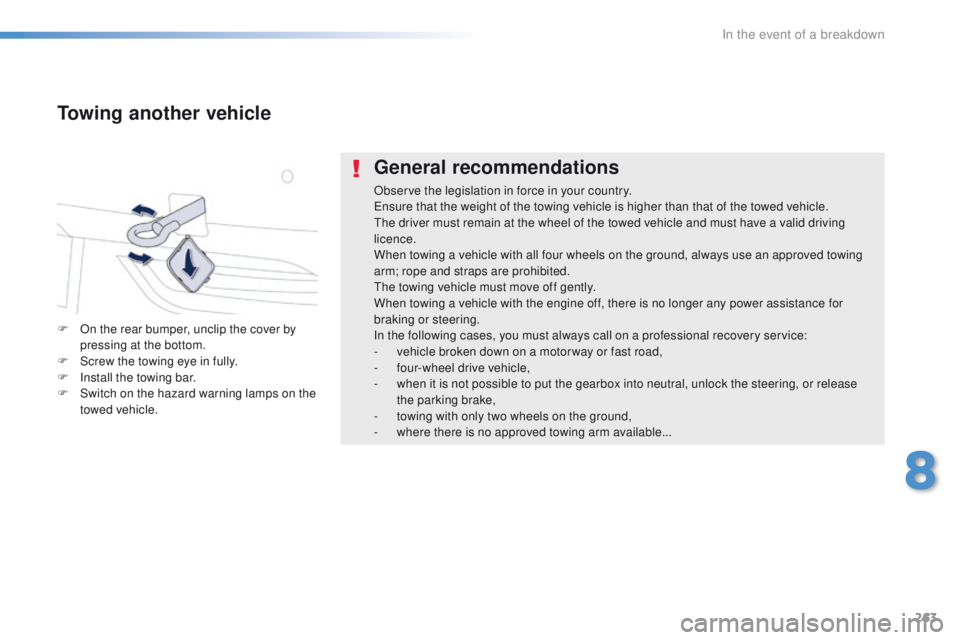
Towing another vehicle
F On the rear bumper, unclip the cover by pressing at the bottom.
F
S
crew the towing eye in fully.
F
I
nstall the towing bar.
F
S
witch on the hazard warning lamps on the
towed vehicle.
8
In the event of a breakdown