Page 201 of 398
199
308_en_Chap06_conduite_ed02-2015
the system will be deactivated
a utomatically if a trailer is being
towed or a bicycle carrier is fitted on
a towbar (vehicle fitted with a towbar
installed in line with the manufacturer's
recommendations).
Deactivation / Activation of
the front and rear parking
sensors
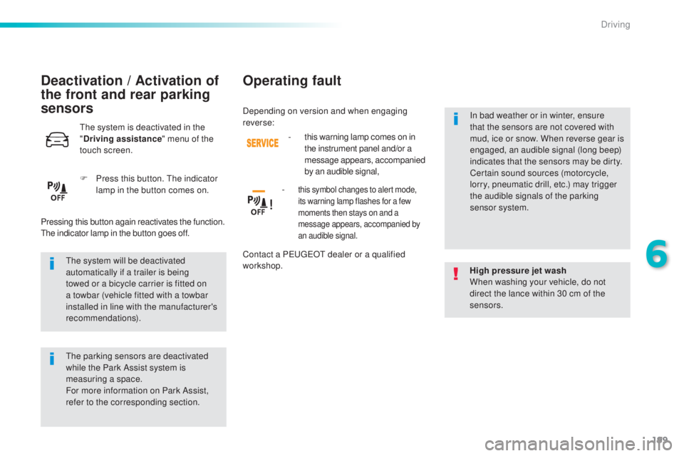
the system is deactivated in the
" D
riving assistance " menu of the
touch screen.
F
Pr
ess this button.
the i
ndicator
lamp in the button comes on.
Pressing this button again reactivates the function.
the i
ndicator lamp in the button goes off.
the p
arking sensors are deactivated
while the Park Assist system is
measuring a space.
For more information on Park Assist,
refer to the corresponding section. High pressure jet wash
When washing your vehicle, do not
direct the lance within 30 cm of the
sensors.
Operating fault
- this warning lamp comes on in
t
he instrument panel and/or a
message appears, accompanied
by an audible signal,
-
this symbol changes to alert mode,
its warning lamp flashes for a few
moments then stays on and a
message appears, accompanied by
an audible signal.
Contact a Peu geOt d ealer or a qualified
workshop. In bad weather or in winter, ensure
that the sensors are not covered with
mud, ice or snow. When reverse gear is
engaged, an audible signal (long beep)
indicates that the sensors may be dirty.
Certain sound sources (motorcycle,
lorry, pneumatic drill, etc.) may trigger
the audible signals of the parking
sensor system.
Depending on version and when engaging
reverse:
6
Driving
Page 202 of 398
200
308_en_Chap06_conduite_ed02-2015
Reversing camera
Opening the tailgate causes the display
to disappear.
the
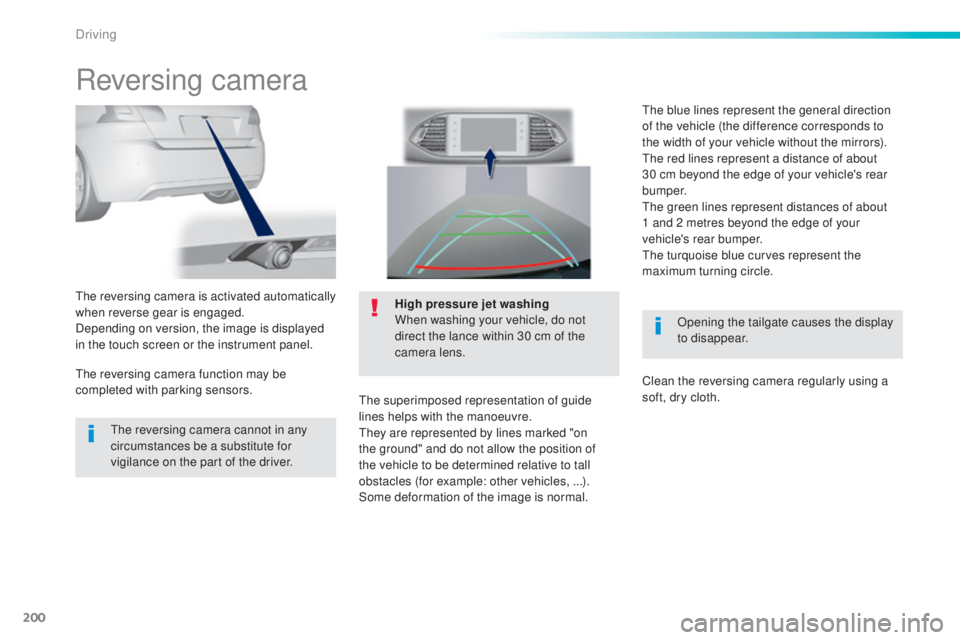
reversing camera is activated automatically
when reverse gear is engaged.
Depending on version, the image is displayed
in the touch screen or the instrument panel. High pressure jet washing
When washing your vehicle, do not
direct the lance within 30 cm of the
camera lens.
the s
uperimposed representation of guide
lines helps with the manoeuvre.
the
y are represented by lines marked "on
the ground" and do not allow the position of
the vehicle to be determined relative to tall
obstacles (for example: other vehicles, ...).
Some deformation of the image is normal.
the r
eversing camera cannot in any
circumstances be a substitute for
vigilance on the part of the driver.
the r
eversing camera function may be
completed with parking sensors.
the b
lue lines represent the general direction
of the vehicle (the difference corresponds to
the width of your vehicle without the mirrors).
the r
ed lines represent a distance of about
30 cm beyond the edge of your vehicle's rear
b u m p e r.
the g
reen lines represent distances of about
1
a
nd 2 metres beyond the edge of your
vehicle's rear bumper.
the t
urquoise blue curves represent the
maximum turning circle.
Clean the reversing camera regularly using a
soft, dry cloth.
Driving
Page 206 of 398
204
308_en_Chap06_conduite_ed02-2015
F Move for wards slowly until a message is
displayed, accompanied by an audible
signal, asking you to engage reverse gear.
F
Se
lect reverse, release the steering wheel
and start moving without exceeding 5 mph
(8 km/h). F
the a ssisted parking manoeuvre is in
progress.
Wi
thout exceeding 5 mph (8 km/h), move
for wards and backwards, aided by the
warnings from the "Parking sensors"
system, until the indication of the end of the
manoeuvre. F At t
he end of the manoeuvre, the operating
indicator lamp goes out in the instrument
panel, accompanied by a message and an
audible signal.
the a
ssistance is deactivated: you can
take over control.
Driving
Page 207 of 398
205
308_en_Chap06_conduite_ed02-2015
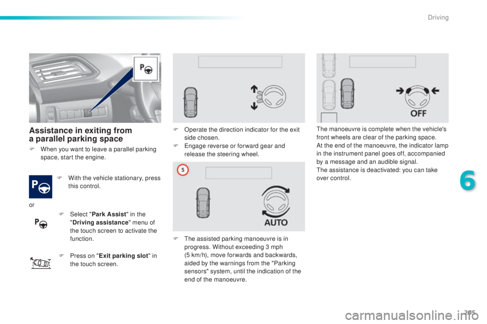
Assistance in exiting from
a parallel parking space
F With the vehicle stationary, press
t
his control.
F
Pr
ess on " Exit parking slot " in
the touch screen. F
Op
erate the direction indicator for the exit
side chosen.
F
e
ng
age reverse or for ward gear and
release the steering wheel.
F
t
he a
ssisted parking manoeuvre is in
progress. Without exceeding 3 mph
(5
k
m/h), move for wards and backwards,
aided by the warnings from the "Parking
sensors" system, until the indication of the
end of the manoeuvre.
the m
anoeuvre is complete when the vehicle's
front wheels are clear of the parking space.
At the end of the manoeuvre, the indicator lamp
in the instrument panel goes off, accompanied
by a message and an audible signal.the a ssistance is deactivated: you can take
over control.
F
Wh
en you want to leave a parallel parking
space, start the engine.
or F
Selec
t "Park Assist " in the
" Driving assistance " menu of
the touch screen to activate the
function.
6
Driving
Page 208 of 398
206
308_en_Chap06_conduite_ed02-2015
F Once you have identified a
parking zone, press this control
at the steering wheel,
Assistance with bay parking
manoeuvres
F Select " P ark Assist" in the
" Driving assistance " menu of
the touch screen to activate the
function. F
Op
erate the direction indicator on the
parking side chosen to activate the
measurement function. You should drive
at a distance of between 0.5 m and 1.5 m
from the row of parked vehicles.
F
Dr
ive slowly following the instructions until
the system finds a free space. F
Mov
e for wards slowly until a message is
displayed, accompanied by an audible
signal, asking you to engage reverse gear.
or
F
Li
mit the speed of the vehicle to
a maximum of 12 mph (20 km/h)
and select " Star t parking in a
bay " on the touch screen. When several successive bays are
found, the vehicle will be directed
towards the last one.
Driving
Page 209 of 398
207
308_en_Chap06_conduite_ed02-2015
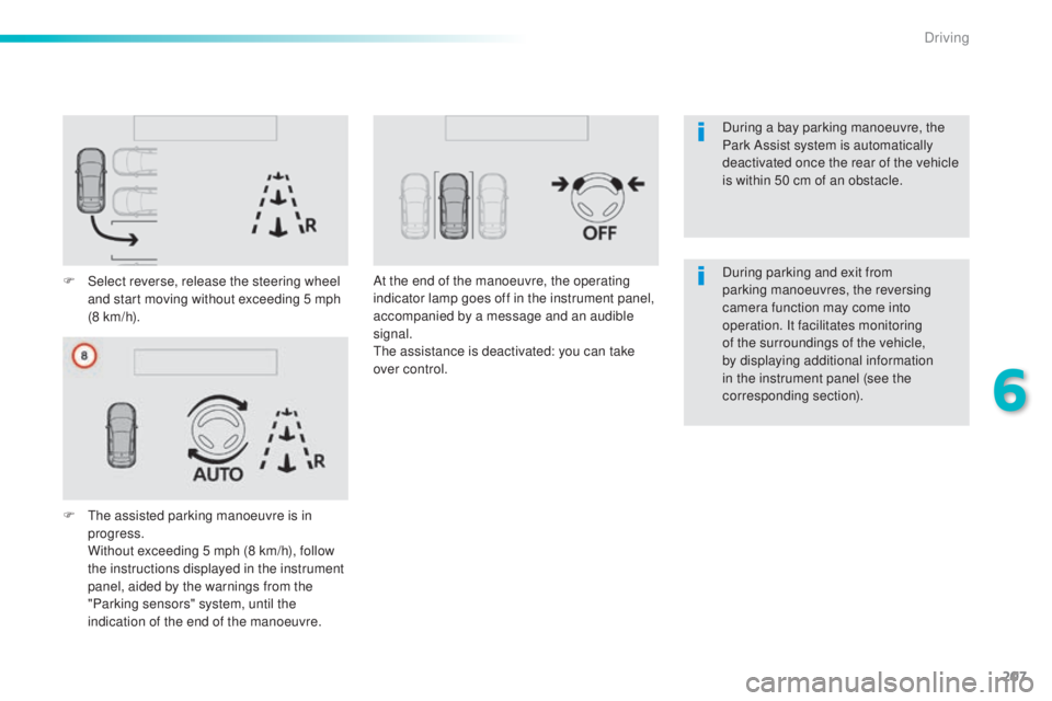
F Select reverse, release the steering wheel
and start moving without exceeding 5 mph
(8 km/h).
F
t
he a
ssisted parking manoeuvre is in
progress.
Wi
thout exceeding 5 mph (8 km/h), follow
the instructions displayed in the instrument
panel, aided by the warnings from the
"Parking sensors" system, until the
indication of the end of the manoeuvre. At the end of the manoeuvre, the operating
indicator lamp goes off in the instrument panel,
accompanied by a message and an audible
signal.
the a
ssistance is deactivated: you can take
over control. During parking and exit from
parking manoeuvres, the reversing
camera function may come into
operation. It facilitates monitoring
of the surroundings of the vehicle,
by displaying additional information
in the instrument panel (see the
corresponding section). During a bay parking manoeuvre, the
Park Assist system is automatically
deactivated once the rear of the vehicle
is within 50 cm of an obstacle.
6
Driving
Page 260 of 398
258
308_en_Chap08_en-cas-de-panne_ed02-2015
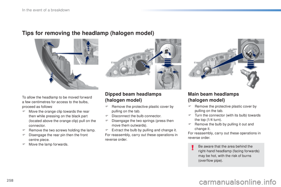
Main beam headlamps
(halogen model)
F Remove the protective plastic cover by
p
ulling on the tab.
F
t
ur
n the connector (with its bulb) towards
the top (1/4 turn).
F
Re
move the bulb by pulling it out and
change it.
For reassembly, carry out these operations in
reverse order.
Dipped beam headlamps
(halogen model)
F Remove the protective plastic cover by
p
ulling on the tab.
F
Di
sconnect the bulb connector.
F
Disenga
ge the two springs (press then
move them outwards).
F
e
xt
ract the bulb by pulling and change it.
For reassembly, carry out these operations in
reverse order.
Be aware that the area behind the
right-hand headlamp (facing forwards)
may be hot, with the risk of burns
(over flow
p
ipe).
to al
low the headlamp to be moved for ward
a few centimetres for access to the bulbs,
proceed as follows:
F Move the orange clip towards the rear
t hen while pressing on the black part
(located above the orange clip) pull on the
connector.
F
Re
move the two screws holding the lamp.
F
Disenga
ge the rear pin then the front
centre piece.
F
Mov
e the lamp for wards.
Tips for removing the headlamp (halogen model)
In the event of a breakdown
Page 261 of 398
259
308_en_Chap08_en-cas-de-panne_ed02-2015
For reassembly, carry out these operations in
reverse order.
Direction indicators
(halogen model)
Faster flashing of a direction indicator
warning lamp (left or right) indicates a
failed bulb on that side.
Daytime running lamps /
sidelamps
("full LED" technology model)
For the replacement of this type of "full LeD"
l ight emitting diode lamps, contact a Peu geOt
d
ealer or a qualified workshop.
Direction indicators
("full LED" technology model)
the direction indicator bulb is located below
t he front lamp.
F
u
nc
lip the finisher by pulling at the top
(cut-out).
F
u
ns
crew the bulb holder (1/4 turn).
F
Ch
ange the failed bulb.
For reassembly, carry out these operations in
reverse order. Faster flashing of a direction indicator
warning lamp (left or right) indicates a
failed bulb on that side.
F
u
ns
crew the bulb holder (1/4 turn).
F
Re
move the bulb holder.
F
Ch
ange the failed bulb.
8
In the event of a breakdown