Page 81 of 636

2 Instruments and controls
Instrument panel...................................2-2
Meters and gauges ................................2-4
Speedometer and odometer .....................2-5
Tachometer ....................................2-7
Engine coolant temperature gauge ...............2-7
Fuel gauge ....................................2-8
Auxiliary gauges (if so equipped) .................2-9
Diesel Exhaust Fluid (DEF) Level
(if so equipped) ............................... 2-10
Off-road monitor (if so equipped) ................2-11
Trip computer (if so equipped) ..................2-11
Compass (if so equipped) ......................... 2-16
Warning lights, indicator lights and audible
reminders ........................................ 2-19
Checking lights ............................... 2-20
Warning lights ................................ 2-20
Indicator lights ................................ 2-26
Audible reminders ............................. 2-29
Vehicle Information Display (if so equipped) .........2-29
How to use the vehicle information display .......2-30
Startup display ................................ 2-30
Settings ...................................... 2-31
Vehicle information display warnings and
indicators ..................................... 2-39Diesel warnings and indicators
(if so equipped)
............................... 2-44
Security systems ................................. 2-44
Vehicle security system ......................... 2-45
NISSAN vehicle immobilizer system .............2-46
Wiper and washer switch ......................... 2-47
Switch operation .............................. 2-48
Rain-sensing auto wiper system
(if so equipped) ............................... 2-49
Rear window and/or outside mirror defroster switch
(if so equipped) .................................. 2-50
Headlight switch ................................. 2-51
Headlight control switch ........................ 2-51
Daytime running light system
(if so equipped) ............................... 2-53
Instrument brightness control ...................2-54
Turn signal switch ................................ 2-54
Turn signal .................................... 2-54
Lane change signal ............................ 2-54
Fog
light switch (if so equipped) ...................2-55
Horn ............................................ 2-55
Cargo lamp switch ................................ 2-56
Climate controlled seat switches (if so equipped) ....2-56
Heated seat switches (if so equipped) ..............2-57
Page 85 of 636
1. Tachometer
2. Warning and indicator lights
3. Vehicle information displayOdometer
Outside temperature display 4. Speedometer
5. Fuel gauge
6. Engine coolant temperature gauge
Type A (if so equipped)
LIC3100
METERS AND GAUGES
2-4Instruments and controls
Page 86 of 636
1. Tachometer
2. Warning and indicator lights
3. Speedometer
4. Fuel gauge5. Trip computer
Odometer
Outside temperature display
6. Engine coolant temperature gauge
SPEEDOMETER AND ODOMETER
This vehicle is equipped with a speedometer and
odometer. The speedometer is located on the
right side of the meter cluster. The odometer is
located in the vehicle information display (Type A)
(if so equipped) or the trip computer (Type B) (if
so equipped) to the left of the speedometer and
can be accessed with the vehicle in the ON
position.
Type B (if so equipped)
LIC3497
Instruments and controls2-5
Page 88 of 636
Changing the display
Pushing the TRIP RESET
�3switch on the left
side of the instrument panel changes the display
as follows:
ODO →Trip
→Trip→ODO
Resetting the trip odometer
Pushing the TRIP RESET switch
�3for 1 second
resets the currently displayed trip odometer to
zero.
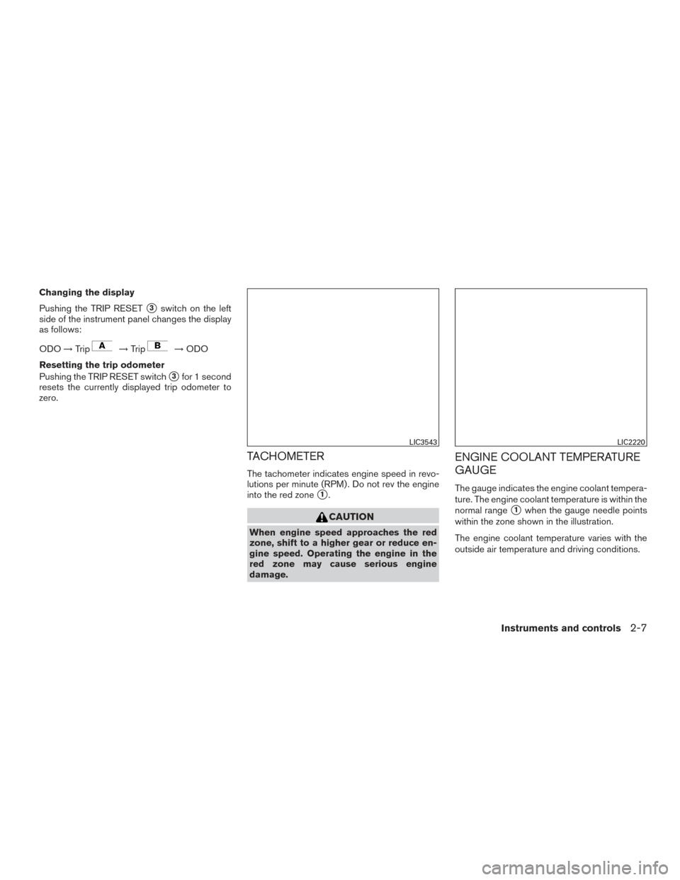
TACHOMETER
The tachometer indicates engine speed in revo-
lutions per minute (RPM) . Do not rev the engine
into the red zone
�1.
CAUTION
When engine speed approaches the red
zone, shift to a higher gear or reduce en-
gine speed. Operating the engine in the
red zone may cause serious engine
damage.
ENGINE COOLANT TEMPERATURE
GAUGE
The gauge indicates the engine coolant tempera-
ture. The engine coolant temperature is within the
normal range
�1when the gauge needle points
within the zone shown in the illustration.
The engine coolant temperature varies with the
outside air temperature and driving conditions.
LIC3543LIC2220
Instruments and controls2-7
Page 89 of 636
 end of the normal
range, reduce vehicle speed to decrease
temperature. If the gauge is over the nor-
mal range, stop the vehicle a")
CAUTION
If the gauge indicates coolant tempera-
ture near the hot (H) end of the normal
range, reduce vehicle speed to decrease
temperature. If the gauge is over the nor-
mal range, stop the vehicle as soon as
safely possible. If the engine is over-
heated, continued operation of the vehicle
may seriously damage the engine. For ad-
ditional information, refer to “If your ve-
hicle overheats” in the “In case of emer-
gency” section of this manual for
immediate action required.
FUEL GAUGE
The gauge indicates theapproximatefuel level
in the tank.
The gauge may move slightly during braking,
turning, acceleration, or going up or down hills.
The gauge needle returns to 0 (Empty) after the
ignition switch is placed in the OFF position.
The low fuel warning light comes on when the
amount of fuel in the tank is getting low. Refill the fuel tank before the gauge regis-
ters 0 (Empty) .
The
indicates that the fuel-filler door is
located on the driver’s side of the vehicle.
CAUTION
● If the vehicle runs out of fuel, theMalfunction Indicator Light (MIL) may
come on. Refuel as soon as possible.
After a few driving trips. the
light
should turn off. If the light remains on
after a few driving trips, have the vehicle
inspected. It is recommended you visit a
NISSAN dealer for this service.
● For additional information, refer to
“Malfunction Indicator Light (MIL)” in
this section.
LIC2222
2-8Instruments and controls
Page 90 of 636

1. Exhaust temperature gauge (if so equipped)
2. Automatic Transmission fluid temperaturegauge
3. Turbo meter (if so equipped)
4. Engine oil pressure gauge
5. Engine")
AUXILIARY GAUGES (if so equipped)
1. Exhaust temperature gauge (if so equipped)
2. Automatic Transmission fluid temperaturegauge
3. Turbo meter (if so equipped)
4. Engine oil pressure gauge
5. Engine oil temperature gauge
6. Voltmeter Exhaust temperature gauge (if so
equipped)
For additional information, refer to the “Titan Die-
sel Owner’s Manual”.
Automatic Transmission fluid temperature
gauge
This gauge indicates the temperature of the au-
tomatic transmission fluid.
CAUTION
●
This gauge is not designed to indicate
low automatic transmission fluid level.
Use the dipstick to check the fluid level.
For additional information, refer to “6-
speed automatic transmission fluid” in
the “Do-it-yourself” section of this
manual.
● If the gauge indicates automatic trans-
mission fluid temperature over the nor-
mal range, stop the vehicle as soon as
safely possible. It is recommended that
you have the vehicle checked by a
NISSAN dealer. Continued operation of
the vehicle may seriously damage the
transmission.
Turbo meter (if so equipped)
For additional information, refer to the “Titan Die-
sel Owner’s Manual”.
Engine oil pressure gauge
The gauge indicates the engine lubrication sys-
tem oil pressure while the engine is running. The
bar should be in the middle of the gauge when
the engine is running.
LIC3390
Instruments and controls2-9
Page 91 of 636

CAUTION
●This gauge is not designed to indicate
low engine oil level. Use the dipstick to
check the oil level. For additional infor-
mation, refer to “Engine oil” in the “Do-
it-yourself” section of this manual.
● If the gauge needle does not move with
the proper amount of engine oil, it is
recommended that you have the vehicle
checked by a NISSAN dealer. Continued
vehicle operation in such a condition
could cause serious damage to the
engine.
Engine oil temperature gauge
This gauge measures the temperature of the en-
gine oil.
Voltmeter
When the ignition switch is placed in the ON
position, the voltmeter indicates the battery volt-
age. When the engine is running, it indicates the
generator voltage. While cranking the engine, the volts drop below
the normal range. If the range is not within the
normal range (11 – 15 volts) while the engine is
running, it may indicate that the charging system
is not functioning properly. Have the system
checked. It is recommended that you visit a
NISSAN dealer for this service.
DIESEL EXHAUST FLUID (DEF)
LEVEL (if so equipped)
This gauge measures the DEF level remaining in
the vehicle. For additional information, refer to
“Fuel and refueling” in the “Titan Diesel Owner’s
Supplement”.
LIC3479
2-10Instruments and controls
Page 94 of 636
Time
The time mode shows the time the vehicle has
been on since the last reset. The displayed time
can be reset by pressing the ENTER button on
the steering wheel for more than approximately
1 second.
Tire info
The tire info mode shows the pressure of each
tire. To see the individual tire pressures, press the
ENTER button when the desired tire is shown.
The tire pressures are displayed as follows:● FL (Front Left)
● FR (Front Right)
● RL (Rear Left)
● RR (Rear Right)
To return to the main menu selections, scroll to
“EXIT” and press ENTER.
Settings
The settings mode allows the user to change the
trip computer display units and set maintenance
reminders. To select the desired menu item,
press the ENTER button when it is shown. The
menu items are displayed as follows:
● Engine Oil
● Oil Filter
● Rotation
● Other
● Units
LIC3507LIC3508LIC3509
Instruments and controls2-13