2016 NISSAN NOTE start
[x] Cancel search: startPage 3219 of 3641

UNBALANCE STEERING WHEEL TURNING FORCE (TORQUE VARIATION)
STC-35
< SYMPTOM DIAGNOSIS >
C
D E
F
H I
J
K L
M A
B
STC
N
O P
UNBALANCE STEERING WHEEL TU RNING FORCE (TORQUE VARIA-
TION)
DescriptionINFOID:0000000012431981
Unbalance steering wheel turning force (torque variation).
Diagnosis ProcedureINFOID:0000000012431982
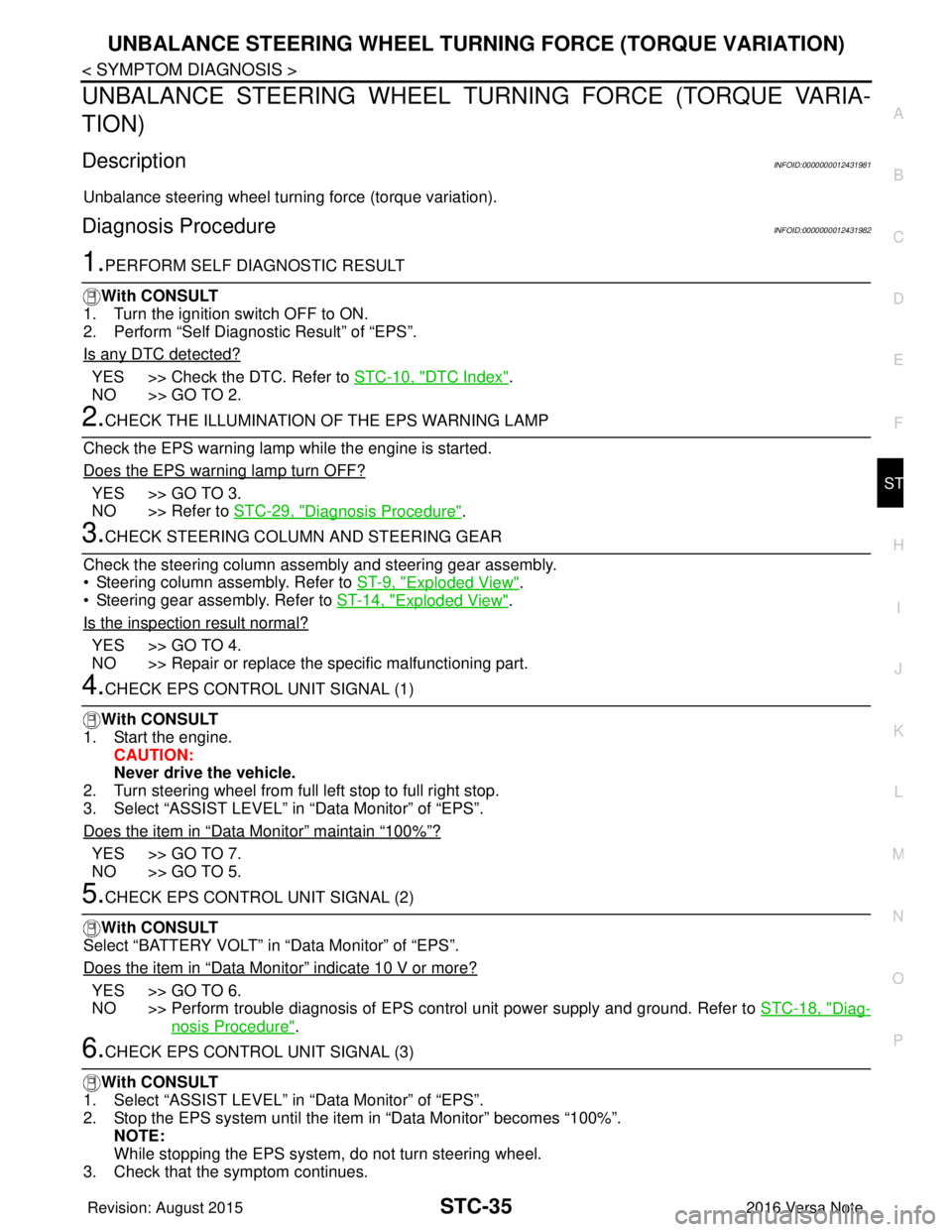
1.PERFORM SELF DIAGNOSTIC RESULT
With CONSULT
1. Turn the ignition switch OFF to ON.
2. Perform “Self Diagnostic Result” of “EPS”.
Is any DTC detected?
YES >> Check the DTC. Refer to STC-10, "DTC Index".
NO >> GO TO 2.
2.CHECK THE ILLUMINATION OF THE EPS WARNING LAMP
Check the EPS warning lamp while the engine is started.
Does the EPS warning lamp turn OFF?
YES >> GO TO 3.
NO >> Refer to STC-29, "
Diagnosis Procedure".
3.CHECK STEERING COLU MN AND STEERING GEAR
Check the steering column assembly and steering gear assembly.
• Steering column assembly. Refer to ST-9, "
Exploded View".
• Steering gear assembly. Refer to ST-14, "
Exploded View".
Is the inspection result normal?
YES >> GO TO 4.
NO >> Repair or replace the specific malfunctioning part.
4.CHECK EPS CONTROL UNIT SIGNAL (1)
With CONSULT
1. Start the engine. CAUTION:
Never drive the vehicle.
2. Turn steering wheel from full left stop to full right stop.
3. Select “ASSIST LEVEL” in “Data Monitor” of “EPS”.
Does the item in
“Data Monitor” maintain “100%”?
YES >> GO TO 7.
NO >> GO TO 5.
5.CHECK EPS CONTROL UNIT SIGNAL (2)
With CONSULT
Select “BATTERY VOLT” in “Data Monitor” of “EPS”.
Does the item in
“Data Monitor” indicate 10 V or more?
YES >> GO TO 6.
NO >> Perform trouble diagnosis of EPS control unit power supply and ground. Refer to STC-18, "
Diag-
nosis Procedure".
6.CHECK EPS CONTROL UNIT SIGNAL (3)
With CONSULT
1. Select “ASSIST LEVEL” in “Data Monitor” of “EPS”.
2. Stop the EPS system until the item in “Data Monitor” becomes “100%”. NOTE:
While stopping the EPS system, do not turn steering wheel.
3. Check that the symptom continues.
Revision: August 2015 2016 Versa Note
cardiagn.com
Page 3220 of 3641

STC-36
< SYMPTOM DIAGNOSIS >
UNBALANCE STEERING WHEEL TURNING FORCE (TORQUE VARIATION)
Does the symptom continue?
YES >> GO TO 7.
NO >> The assist torque decreases because of protection function. This is not malfunction. Inspection
End.
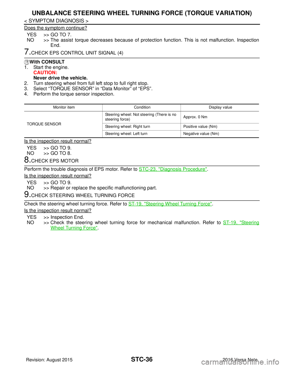
7.CHECK EPS CONTROL UNIT SIGNAL (4)
With CONSULT
1. Start the engine.
CAUTION:
Never drive the vehicle.
2. Turn steering wheel from full left stop to full right stop.
3. Select “TORQUE SENSOR” in “Data Monitor” of “EPS”.
4. Perform the torque sensor inspection.
Is the inspection result normal?
YES >> GO TO 9.
NO >> GO TO 8.
8.CHECK EPS MOTOR
Perform the trouble diagnosis of EPS motor. Refer to STC-23, "
Diagnosis Procedure".
Is the inspection result normal?
YES >> GO TO 9.
NO >> Repair or replace the specific malfunctioning part.
9.CHECK STEERING WHEEL TURNING FORCE
Check the steering wheel turning force. Refer to ST-19, "
Steering Wheel Turning Force".
Is the inspection result normal?
YES >> Inspection End.
NO >> Check the steering wheel turning force for mechanical malfunction. Refer to ST-19, "
Steering
Wheel Turning Force".
Monitor item ConditionDisplay value
TORQUE SENSOR Steering wheel: Not steering (There is no
steering force)
Approx. 0 Nm
Steering wheel: Right turn Positive value (Nm)
Steering wheel: Left turn Negative value (Nm)
Revision: August 2015 2016 Versa Note
cardiagn.com
Page 3226 of 3641

STEERING WHEELST-5
< BASIC INSPECTION >
C
DE
F
H I
J
K L
M A
B
ST
N
O P
BASIC INSPECTION
STEERING WHEEL
InspectionINFOID:0000000012430497
CONDITION OF INSTALLATION
• Check installation conditions of steering gear, front suspension, axle and steering column.
• Check if movement exists when steering wheel is mo ved up and down, to the left and right and to the axial
direction.
• Verify that the steering gear nuts are tightened to specification. Refer to ST-14, "
Exploded View".
STEERING WHEEL PLAY
1. Set the front wheels and tires in the straight-ahead position, start engine, then lightly turn steering wheel
to the left and right until the front wheels start to move. Measure steering wheel movement on the outer
circumference.
2. When the measurement value is outside the standard va lue, check backlash for each joint of steering col-
umn and installation condition of steering gear.
STEERING WHEEL NEUTRAL POSITION
Check steering wheel neutral position using the following procedure:
1. Confirm that front wheel alignment is correct. Refer to FSU-8, "
Adjustment".
2. Set the front wheels and tires in the straight-ahead posit ion, check if steering wheel is in the neutral posi-
tion.
3. If it is not in the neutral position, remo ve steering wheel and reinstall it correctly.
4. If the neutral position cannot be attained by repositi oning the steering wheel two teeth or less on steering
stem, loosen the steering gear outer socket lock nuts, then adjust the inner sockets by the same amount
in the opposite direction.
5. Re-check the front wheel alignment. Refer to FSU-8, "
Adjustment".
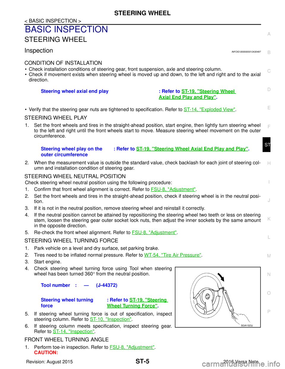
STEERING WHEEL TURNING FORCE
1. Park vehicle on a level and dry surface, set parking brake.
2. Tires need to be inflated normal pressure. Refer to WT-54, "
Tire Air Pressure".
3. Start engine.
4. Check steering wheel turning force using Tool when steering wheel has been turned 360 ° from the neutral position.
5. If steering wheel turning force is out of specification, inspect steering column. Refer to ST-10, "
Inspection".
6. If steering column meets specification, inspect steering gear. Refer to ST-14, "
Inspection".
FRONT WHEEL TURNING ANGLE
1. Perform toe-in inspection. Refer to FSU-8, "Adjustment".
CAUTION: Steering wheel axial end play : Refer to
ST-19, "
Steering Wheel
Axial End Play and Play".
Steering wheel play on the
outer circumference : Refer to
ST-19, "
Steering Wheel Axia l End Play and Play".
Tool number : — (J-44372)
Steering wheel turning
force : Refer to
ST-19, "
Steering
Wheel Turning Force".
SGIA1523J
Revision: August 2015 2016 Versa Note
cardiagn.com
Page 3239 of 3641

ST-18
< UNIT DISASSEMBLY AND ASSEMBLY >
STEERING GEAR AND LINKAGE
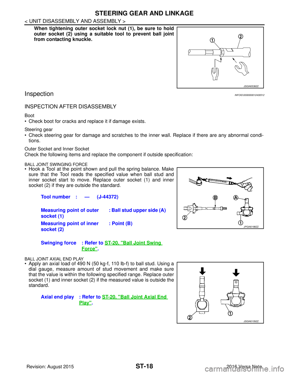
When tightening outer socket lock nut (1), be sure to hold
outer socket (2) using a suitable tool to prevent ball joint
from contacting knuckle.
InspectionINFOID:0000000012430512
INSPECTION AFTER DISASSEMBLY
Boot
• Check boot for cracks and replace it if damage exists.
Steering gear
• Check steering gear for damage and scratches to the inner wall. Replace if there are any abnormal condi- tions.
Outer Socket and Inner Socket
Check the following items and replace the component if outside specification:
BALL JOINT SWINGING FORCE• Hook a Tool at the point shown and pull the spring balance. Make
sure that the Tool reads the specified value when ball stud and
inner socket start to move. Replace outer socket (1) and inner
socket (2) if they are outside the standard.
BALL JOINT AXIAL END PLAY
• Apply an axial load of 490 N (50 kg-f, 110 lb-f) to ball stud. Using adial gauge, measure amount of stud movement and make sure
that the value is within the following specified range. Replace outer
socket (1) and inner socket (2) if the measured value is outside the
standard.
JSGIA0538ZZ
Tool number : — (J-44372)
Measuring point of outer
socket (1) : Ball stud upper side (A)
Measuring point of inner
socket (2) : Point (B)
Swinging force : Refer to ST-20, "
Ball Joint Swing
Force".
Axial end play : Refer to ST-20, "
Ball Joint Axial End
Play".
JPGIA0188ZZ
JSGIA0109ZZ
Revision: August 2015 2016 Versa Note
cardiagn.com
Page 3258 of 3641
![NISSAN NOTE 2016 Service Repair Manual GEAR OILTM-17
< PERIODIC MAINTENANCE > [5MT: RS5F91R]
C
EF
G H
I
J
K L
M A
B
TM
N
O P
PERIODIC MAINTENANCE
GEAR OIL
InspectionINFOID:0000000012430947
GEAR OIL LEAKS
Make sure that gear oil is not l ea NISSAN NOTE 2016 Service Repair Manual GEAR OILTM-17
< PERIODIC MAINTENANCE > [5MT: RS5F91R]
C
EF
G H
I
J
K L
M A
B
TM
N
O P
PERIODIC MAINTENANCE
GEAR OIL
InspectionINFOID:0000000012430947
GEAR OIL LEAKS
Make sure that gear oil is not l ea](/manual-img/5/57363/w960_57363-3257.png)
GEAR OILTM-17
< PERIODIC MAINTENANCE > [5MT: RS5F91R]
C
EF
G H
I
J
K L
M A
B
TM
N
O P
PERIODIC MAINTENANCE
GEAR OIL
InspectionINFOID:0000000012430947
GEAR OIL LEAKS
Make sure that gear oil is not l eaking from transaxle or around it.
GEAR OIL LEVEL
1. Remove filler plug (1) and gasket from transaxle case.
2. Check the gear oil level from filler plug hole as shown.
CAUTION:
Do not start engine whil e checking gear oil level.
3. Install a new gasket on filler plug and then install filler plug to transaxle case.
CAUTION:
Do not reuse gasket.
4. Tighten filler plug to the specified torque. Refer to TM-26,
"Exploded View".
DrainingINFOID:0000000012430948
1. Start engine and let it run to warm up transaxle.
2. Stop engine. Remove drain plug (1) and gasket, using suitable
tool and then drain gear oil.
3. Install a new gasket on drain plug (1) and install drain plug to clutch housing, using suitable tool.
CAUTION:
Do not reuse gasket.
4. Tighten drain plug (1) to the specified torque. Refer to TM-26,
"Exploded View".
RefillingINFOID:0000000012430949
1. Remove filler plug (1) and gasket from transaxle case.
2. Fill with new gear oil until gear oil level reaches the specified limit at filler plug hole as shown.
CAUTION:
Do not start engine whil e checking gear oil level.
3. Install a new gasket on filler plug and then install filler plug to transaxle case.
CAUTION:
Do not reuse gasket.
4. Tighten filler plug to the specified torque. Refer to TM-26, "
Exploded View".
SCIA7119E
PCIB1504E
Oil capacity
and viscosity: Refer to
MA-11, "Fluids and Lubri-
cants".
SCIA7119E
Revision: August 2015 2016 Versa Note
cardiagn.com
Page 3266 of 3641
![NISSAN NOTE 2016 Service Repair Manual TRANSAXLE ASSEMBLYTM-25
< UNIT REMOVAL AND INSTALLATION > [5MT: RS5F91R]
C
EF
G H
I
J
K L
M A
B
TM
N
O P
• Do not reuse self-tapping bolt.
• Tighten transaxle assembly bolts to the specified torqu NISSAN NOTE 2016 Service Repair Manual TRANSAXLE ASSEMBLYTM-25
< UNIT REMOVAL AND INSTALLATION > [5MT: RS5F91R]
C
EF
G H
I
J
K L
M A
B
TM
N
O P
• Do not reuse self-tapping bolt.
• Tighten transaxle assembly bolts to the specified torqu](/manual-img/5/57363/w960_57363-3265.png)
TRANSAXLE ASSEMBLYTM-25
< UNIT REMOVAL AND INSTALLATION > [5MT: RS5F91R]
C
EF
G H
I
J
K L
M A
B
TM
N
O P
• Do not reuse self-tapping bolt.
• Tighten transaxle assembly bolts to the specified torque. The illus- tration is the view from the engine.
InspectionINFOID:0000000012430963
INSPECTION AFTER INSTALLATION
• Check the operation of the control linkage. Refer to TM-21, "Inspection".
• Before starting engine, check oil/fluid levels incl uding engine coolant and engine oil. If less than required
quantity, fill to the specified level. Refer to MA-11, "
Fluids and Lubricants".
• Use procedure below to check for fuel leaks.
• Turn ignition switch ON (with engine stopped). With fuel pressure applied to fuel piping, check for fuel leaks at connection points.
• Start engine. With engine speed increased, check again for fuel leaks at connection points.
• Run engine to check for unusual noise and vibration. NOTE:
If hydraulic pressure inside timing chain tensioner drops after removal and installation, slack in the guide
may generate a pounding noise during and just after engine start. However, this is normal. Noise will stop
after hydraulic pressure rises.
• Warm up engine thoroughly to make sure there is no lea ks of fuel, exhaust gas, or any oils/fluids including
engine oil and engine coolant.
• Bleed air from passages in lines and hoses, such as in cooling system.
• After cooling down engine, again check oil/fluid levels including engine oil and engine coolant. Refill to spec-
ified level, if necessary.
• Summary of the inspection items:
*Power steering fluid, brake fluid, etc.
Bolt symbol
ABC D
Insertion direction Transaxle to
engine Engine to transaxle
Quantity 2321
Bolt length
() mm (in) 55 (2.17)
49 (1.93) 69 (2.72)
Tightening torque
N·m (kg-m, ft-lb) 48.0 (4.9, 35)
JPDIC0813ZZ
Item
Before starting engine Engine runningAfter engine stopped
Engine coolant LevelLeaks Level
Engine oil LevelLeaks Level
Transmission/
transaxle fluid CVT Models
LeaksLevel/Leaks Leaks
M/T Models Level/Leaks LeaksLevel/Leaks
Other oils and fluids* LevelLeaks Level
Fuel LeaksLeaks Leaks
Exhaust gas —Leaks —
Revision: August 2015 2016 Versa Note
cardiagn.com
Page 3309 of 3641
![NISSAN NOTE 2016 Service Repair Manual TM-68
< SYSTEM DESCRIPTION >[CVT: RE0F11A]
COMPONENT PARTS
TIMING CHART
CVT CONTROL SYSTEM : Sh
ift Position IndicatorINFOID:0000000012431007
TCM transmits shift position signal to combination meter v NISSAN NOTE 2016 Service Repair Manual TM-68
< SYSTEM DESCRIPTION >[CVT: RE0F11A]
COMPONENT PARTS
TIMING CHART
CVT CONTROL SYSTEM : Sh
ift Position IndicatorINFOID:0000000012431007
TCM transmits shift position signal to combination meter v](/manual-img/5/57363/w960_57363-3308.png)
TM-68
< SYSTEM DESCRIPTION >[CVT: RE0F11A]
COMPONENT PARTS
TIMING CHART
CVT CONTROL SYSTEM : Sh
ift Position IndicatorINFOID:0000000012431007
TCM transmits shift position signal to combination meter via CAN communication. The actual shift position is
displayed on combination meter according to the signal.
CVT CONTROL SYSTEM : Malfunc tion Indicator Lamp (MIL)INFOID:0000000012431008
The malfunction indicator lamp (MIL) is located on the combination
meter.
The MIL will illuminate when the ignition switch is turned ON without
the engine running. This is a bulb check.
When the engine is started, the MIL should turn off. If the MIL
remains illuminated, the on board diagnostic system has detected an
engine system malfunction.
For details, refer to EC-57, "
DIAGNOSIS DESCRIPTION : Malfunc-
tion Indicator Lamp (MIL)".
SHIFT LOCK SYSTEM
SHIFT LOCK SYSTEM : Co mponent Parts LocationINFOID:0000000012431009
JSDIA3607GB
JSBIA1315ZZ
ALDIA0267ZZ
Revision: August 2015 2016 Versa Note
cardiagn.com
Page 3315 of 3641
![NISSAN NOTE 2016 Service Repair Manual TM-74
< SYSTEM DESCRIPTION >[CVT: RE0F11A]
STRUCTURE AND OPERATION
FLUID COOLER & FL
UID WARMER SYSTEM
FLUID COOLER & FLUID WARMER SYSTEM : System DescriptionINFOID:0000000012431015
CVT FLUID COOLER NISSAN NOTE 2016 Service Repair Manual TM-74
< SYSTEM DESCRIPTION >[CVT: RE0F11A]
STRUCTURE AND OPERATION
FLUID COOLER & FL
UID WARMER SYSTEM
FLUID COOLER & FLUID WARMER SYSTEM : System DescriptionINFOID:0000000012431015
CVT FLUID COOLER](/manual-img/5/57363/w960_57363-3314.png)
TM-74
< SYSTEM DESCRIPTION >[CVT: RE0F11A]
STRUCTURE AND OPERATION
FLUID COOLER & FL
UID WARMER SYSTEM
FLUID COOLER & FLUID WARMER SYSTEM : System DescriptionINFOID:0000000012431015
CVT FLUID COOLER SCHEMATIC
COMPONENT DESCRIPTION
CVT Oil Warmer
• The CVT oil warmer (1) is installed on the front part of transaxle
assembly.
• When engine is started while engine and CVT are cold, engine coolant temperature rises more quickly than CVT fluid tempera-
ture. CVT oil warmer is provided with two circuits for CVT and
engine coolant respectively so that warmed engine coolant warms
CVT quickly. This helps shorten CVT warming up time, improving
fuel economy.
• A cooling effect is obtained when CVT fluid temperature is high.
CVT Fluid Cooler (Water-cooling)
• The CVT fluid cooler (water-cooling) is installed in the radiator side tank (right side).
• CVT fluid is cooled by engine coolant.
SHIFT LOCK SYSTEM
Manual valve Distributes the clutch and brake operation pressures (pilot pressure) corresponding to
each shift position.
High clutch/reverse brake switching valve Switches the circuit for the high clutch and the reverse brake.
Torque converter clutch control valve It is operated with the torque converter clutch solenoid valve and it adjusts the tighten-
ing pressure and non-tightening pressure of the torque converter clutch piston of the
torque converter.
Primary pressure control valve It is operated with the primary pressure solenoid valve and adjusts the feed pressure to
the primary pulley.
Primary pressure solenoid valve TM-65, "
CVT CONTROL SYSTEM : Primary Pressure Solenoid Valve"
Low brake solenoid valve TM-65, "CVT CONTROL SYSTEM : Low Brake Solenoid Valve"
High clutch & reverse brake solenoid valveTM-66, "CVT CONTROL SYSTEM : High Clutch & Reverse Brake Solenoid Valve"
Torque converter clutch solenoid valve TM-66, "CVT CONTROL SYSTEM : Torque Converter Clutch Solenoid Valve"
Line pressure solenoid valve TM-66, "CVT CONTROL SYSTEM : Line Pressure Solenoid Valve"
Part name Function
JSDIA4074GB
JSDIA2586ZZ
Revision: August 2015 2016 Versa Note
cardiagn.com