2016 NISSAN NOTE oil change
[x] Cancel search: oil changePage 2342 of 3641
CHASSIS AND BODY MAINTENANCEMA-27
< PERIODIC MAINTENANCE >
C
DE
F
G H
I
J
K L
M B
MA
N
O A
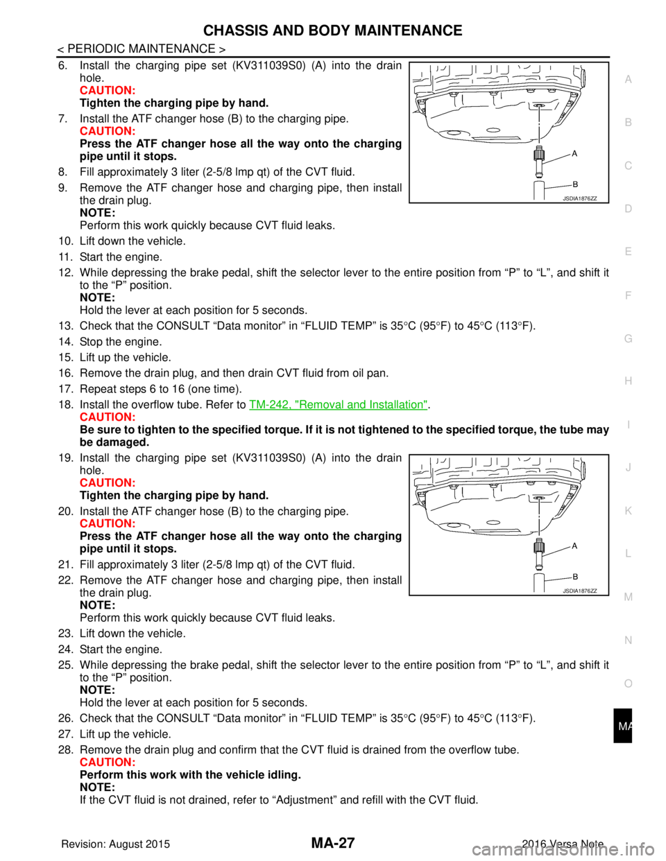
6. Install the charging pipe set (KV311039S0) (A) into the drain
hole.
CAUTION:
Tighten the charging pipe by hand.
7. Install the ATF changer hose (B) to the charging pipe. CAUTION:
Press the ATF changer hose all the way onto the charging
pipe until it stops.
8. Fill approximately 3 liter (2-5 /8 lmp qt) of the CVT fluid.
9. Remove the ATF changer hose and charging pipe, then install the drain plug.
NOTE:
Perform this work quickly because CVT fluid leaks.
10. Lift down the vehicle.
11. Start the engine.
12. While depressing the brake pedal, shift the selector leve r to the entire position from “P” to “L”, and shift it
to the “P” position.
NOTE:
Hold the lever at each position for 5 seconds.
13. Check that the CONSULT “Data monitor” in “FLUID TEMP” is 35°C (95°F) to 45 °C (113 °F).
14. Stop the engine.
15. Lift up the vehicle.
16. Remove the drain plug, and then drain CVT fluid from oil pan.
17. Repeat steps 6 to 16 (one time).
18. Install the overflow tube. Refer to TM-242, "
Removal and Installation".
CAUTION:
Be sure to tighten to the specified torque. If it is not tightened to the specified torque, the tube may
be damaged.
19. Install the charging pipe set (KV311039S0) (A) into the drain hole.
CAUTION:
Tighten the charging pipe by hand.
20. Install the ATF changer hose (B) to the charging pipe. CAUTION:
Press the ATF changer hose all the way onto the charging
pipe until it stops.
21. Fill approximately 3 liter (2-5 /8 lmp qt) of the CVT fluid.
22. Remove the ATF changer hose and charging pipe, then install the drain plug.
NOTE:
Perform this work quickly because CVT fluid leaks.
23. Lift down the vehicle.
24. Start the engine.
25. While depressing the brake pedal, shift the selector leve r to the entire position from “P” to “L”, and shift it
to the “P” position.
NOTE:
Hold the lever at each position for 5 seconds.
26. Check that the CONSULT “Data monitor” in “FLUID TEMP” is 35°C (95°F) to 45 °C (113 °F).
27. Lift up the vehicle.
28. Remove the drain plug and confirm that the CV T fluid is drained from the overflow tube.
CAUTION:
Perform this work with the vehicle idling.
NOTE:
If the CVT fluid is not drained, refer to “Adjustment” and refill with the CVT fluid.
JSDIA1876ZZ
JSDIA1876ZZ
Revision: August 2015 2016 Versa Note
cardiagn.com
Page 2343 of 3641
MA-28
< PERIODIC MAINTENANCE >
CHASSIS AND BODY MAINTENANCE
29. When the flow of CVT fluid slows to a drip, tighten the drain plug to the specified torque. TM-242,
"Removal and Installation".
CAUTION:
Never reuse drain plug gasket.
30. Lift down the vehicle.
31. Select “Work Support” in “TRANSMISSION” using CONSULT.
32. Select “CONFORM CVTF DETERIORTN”.
33. Select “Erase”.
34. Stop the engine.
CVT FLUID : AdjustmentINFOID:0000000012432269
CAUTION:
• Use only Genuine NISSAN CVT Fluid NS-3. Using transmission fluid other than Genuine NISSAN
CVT Fluid NS-3 will damage the CVT, which is not covered by the (NISSAN new vehicle limited) war-
ranty.
• During adjustment of the CVT fluid level, check CO NSULT so that the oil temperature may be main-
tained from 35 to 45 °C (95 to 113 °F).
• Use caution when looking into the drain hole as th ere is a risk of dripping fluid entering the eye.
1. Check that the selector lever is in the “P ” position, then completely engage the parking brake.
2. Start the engine.
3. Adjust the CVT fluid temperature to be approximately 40 °C (104° F).
NOTE:
The CVT fluid is largely affected by temperature. Therefore be sure to use CONSULT and check the
“FLUID TEMP” under “TRANSMISSION” in “Data Monitor” while adjusting.
4. While depressing the brake pedal, shift the selector lever to the entire position from “P” to “L”, and shift it to the “P” position.
NOTE:
Hold the lever at each position for 5 seconds.
5. Lift up the vehicle.
6. Check that there is no CVT fluid leakage.
7. Remove the drain plug. Refer to TM-242, "
Removal and Installation".
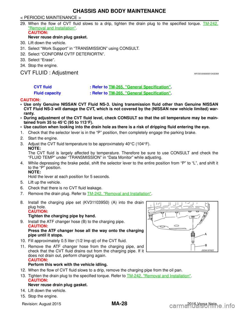
8. Install the charging pipe set (KV311039S0) (A) into the drain plug hole.
CAUTION:
Tighten the charging pipe by hand.
9. Install the ATF changer hose (B) to the charging pipe. CAUTION:
Press the ATF changer hose all the way onto the charging
pipe until it stops.
10. Fill approximately 0.5 liter (1/2 lmp qt) of the CVT fluid.
11. Remove the ATF changer hose from the charging pipe, and check that the CVT fluid drains out from the charging pipe. If it
does not drain out, perform charging again.
CAUTION:
Perform this work with the vehicle idling.
12. When the flow of CVT fluid slows to a drip, remove the charging pipe from the oil pan.
13. Tighten the drain plug to the specified torque. Refer to TM-242, "
Removal and Installation".
CAUTION:
Never reuse drain plug gasket.
14. Lift down the vehicle.
15. Stop the engine. CVT fluid
: Refer to TM-265, "
General Specification".
Fluid capacity : Refer to TM-265, "
General Specification".
JSDIA1876ZZ
Revision: August 2015 2016 Versa Note
cardiagn.com
Page 2369 of 3641
![NISSAN NOTE 2016 Service Repair Manual MWI
SYSTEMMWI-11
< SYSTEM DESCRIPTION > [TYPE A]
C
D
E
F
G H
I
J
K L
M B A
O P
• The combination meter includes an on board diagnosis function.
• The combination meter can be diagnosed with CONSUL](/manual-img/5/57363/w960_57363-2368.png "NISSAN NOTE 2016 Service Repair Manual MWI
SYSTEMMWI-11
< SYSTEM DESCRIPTION > [TYPE A]
C
D
E
F
G H
I
J
K L
M B A
O P
• The combination meter includes an on board diagnosis function.
• The combination meter can be diagnosed with CONSUL")
MWI
SYSTEMMWI-11
< SYSTEM DESCRIPTION > [TYPE A]
C
D
E
F
G H
I
J
K L
M B A
O P
• The combination meter includes an on board diagnosis function.
• The combination meter can be diagnosed with CONSULT.
METER CONTROL FUNCTION LIST
METER SYSTEM : Fail-safeINFOID:0000000012432544
The combination meter activates the fail-safe contro l if CAN communication with each unit is malfunctioning.
System DescriptionReference
Measuring instruments Speedometer
Indicates vehicle speed. MWI-12,
"SPEEDOME-
TER : System De-
scription"
Tachometer
Indicates engine speed. MWI-12, "
TA -
CHOMETER :
System Descrip-
tion"
Shift position indicator
Indicates shift position.MWI-13, "
SHIFT
POSITION INDI-
CATOR : System
Description"
Warning lamp/indicator
lamp
Engine oil pressure warning lamp The warning lamp turns ON or turns OFF,
according to engine hydraulic pressure. MWI-13, "
OIL
PRESSURE
WARNING LAMP
: System Descrip-
tion"
Meter illumination con-
trol
Meter illumination control function
Controls the back light of combination meter. MWI-13, "
METER
ILLUMINATION
CONTROL : Sys-
tem Description"
Information displayOdo/trip meter Indicates mileage.
MWI-14, "
INFOR-
MATION DIS-
PLAY : System
Description"
Engine coolant temperature gauge Indicates engine coolant temperature.
Fuel gaugeIndicates fuel level.
Loose fuel cap warning Indicates loose fuel cap.
Low fuel warning Indicates fuel level.
Trip computer Instant fuel consumption Displays current fuel consumption.
Average fuel consumption Displays average fuel consumption.
Distance to empty Displays distance to empty.
Travel distance
Displays mileage.
Function Specifications
Speedometer Reset to zero by suspending communication.
Tachometer
Illumination control When suspending communication, changes to nighttime mode.
Shift position indicator When suspending communication, not indicate.
Information display Trip com-
puterCurrent fuel consump-
tion
• When reception time of an abnormal signal is 2 seconds or
less, the last received datum is used for calculation to indi-
cate the result.
• When reception time of an abnormal signal is more than two
seconds, the last result calculated during normal condition is
indicated.
Average fuel consump-
tion
Distance to empty
Engine coolant temperature gauge Reset to zero by suspending communication.
Odo/trip meter An indicated value is maintained at communications blackout.
Buzzer The buzzer turns OFF by suspending communication.
Revision: August 2015 2016 Versa Note
cardiagn.com
Page 2420 of 3641
![NISSAN NOTE 2016 Service Repair Manual MWI-62
< SYSTEM DESCRIPTION >[TYPE B]
SYSTEM
• The combination meter includes an on board diagnosis function.
• The combination meter can be diagnosed with CONSULT.
METER CONTROL FUNCTION LIST
MET](/manual-img/5/57363/w960_57363-2419.png "NISSAN NOTE 2016 Service Repair Manual MWI-62
< SYSTEM DESCRIPTION >[TYPE B]
SYSTEM
• The combination meter includes an on board diagnosis function.
• The combination meter can be diagnosed with CONSULT.
METER CONTROL FUNCTION LIST
MET")
MWI-62
< SYSTEM DESCRIPTION >[TYPE B]
SYSTEM
• The combination meter includes an on board diagnosis function.
• The combination meter can be diagnosed with CONSULT.
METER CONTROL FUNCTION LIST
METER SYSTEM : Fail-safeINFOID:0000000012432602
The combination meter activates the fail-safe contro
l if CAN communication with each unit is malfunctioning.
System DescriptionReference
Measuring instruments Speedometer
Indicates vehicle speed. MWI-63,
"SPEEDOME-
TER : System De-
scription"
Tachometer
Indicates engine speed. MWI-64, "
TA -
CHOMETER :
System Descrip-
tion"
Shift position indicator
Indicates shift position.MWI-64, "
SHIFT
POSITION INDI-
CATOR : System
Description"
Warning lamp/indicator
lampEngine oil pressure warning lamp
The warning lamp turns ON or turns OFF,
according to engine hydraulic pressure. MWI-65, "
OIL
PRESSURE
WARNING LAMP
: System Descrip-
tion"
High water temperature warning lamp
Turns ON when engine coolant reaches high
temperature. MWI-64, "
HIGH
WATER TEM-
PERATURE
WARNING LAMP
: System Descrip-
tion"
Meter illumination con-
trol
Meter illumination control function
Controls the back light of combination meter. MWI-66, "
METER
ILLUMINATION
CONTROL : Sys-
tem Description"
Information displayOdo/trip meter Indicates mileage.
MWI-66, "
INFOR-
MATION DIS-
PLAY : System
Description"
Fuel gaugeIndicates fuel level.
Loose fuel cap warning Indicates loose fuel cap.
Ambient temperature Indicates outside air temperature.
Trip computer Instant fuel consumption Displays current fuel consumption.
Average fuel consumption Displays average fuel consumption.
Distance to empty Displays distance to empty.
Travel distance
Displays mileage.
Function Specifications
Speedometer Reset to zero by suspending communication.
Tachometer
Illumination control When suspending communication, changes to nighttime mode.
Shift position indicator When suspending communication, not indicate.
Revision: August 2015 2016 Versa Note
cardiagn.com
Page 2435 of 3641
![NISSAN NOTE 2016 Service Repair Manual MWI
COMBINATION METERMWI-77
< ECU DIAGNOSIS INFORMATION > [TYPE B]
C
D
E
F
G H
I
J
K L
M B A
O P
*1:For Canada
Fail-safeINFOID:0000000012432614
The combination meter activates the fail-safe contro l i](/manual-img/5/57363/w960_57363-2434.png "NISSAN NOTE 2016 Service Repair Manual MWI
COMBINATION METERMWI-77
< ECU DIAGNOSIS INFORMATION > [TYPE B]
C
D
E
F
G H
I
J
K L
M B A
O P
*1:For Canada
Fail-safeINFOID:0000000012432614
The combination meter activates the fail-safe contro l i")
MWI
COMBINATION METERMWI-77
< ECU DIAGNOSIS INFORMATION > [TYPE B]
C
D
E
F
G H
I
J
K L
M B A
O P
*1:For Canada
Fail-safeINFOID:0000000012432614
The combination meter activates the fail-safe contro l if CAN communication with each unit is malfunctioning.
DTC IndexINFOID:0000000012432615
Function Specifications
Speedometer Reset to zero by suspending communication.
Tachometer
Illumination control When suspending communication, changes to nighttime mode.
Shift position indicator When suspending communication, not indicate.
Information display Trip com-
puterCurrent fuel consump-
tion
• When reception time of an abnormal signal is 2 seconds or
less, the last received datum is used for calculation to indi-
cate the result.
• When reception time of an abnormal signal is more than two seconds, the last result calculated during normal condition is
indicated.
Average fuel consump-
tion
Distance to empty
Odo/trip meter An indicated value is maintained at communications blackout.
Buzzer The buzzer turns OFF by suspending communication.
Warning lamp/indicator lamp ABS warning lamp
The lamp turns ON by suspending communication.
Slip indicator lamp
Malfunction indicator lamp (MIL)
VDC OFF indicator lamp
EPS warning lamp
Brake warning lamp
High beam indicator lamp
The lamp turns OFF by suspending communication.
Turn signal indicator lamp
Door warning lamp
Light indicator lamp
Engine oil pressure warning lamp
High water temperature warning
lamp
Key warning lamp
O/D OFF indicator lamp
Shift P warning lamp
Engine start operation indicator lamp
Display contents of CONSULT
Diagnostic item is detected when... Refer to
CAN COMM CIRCUIT
[U1000] When combination meter is not transmitting or receiving CAN communication signal for
2 seconds or more.
MWI-93
CONTROL UNIT (CAN)
[U1010]When detecting error during the initial diagnosis of the CAN controller of combination
meter.
MWI-94
VEHICLE SPEED
[B2205]The abnormal vehicle speed signal is input from the ABS actuator and electric unit (con-
trol unit) for 2 seconds or more.
MWI-95
ENGINE SPEED
[B2267]If ECM continuously transmits abnormal engine speed signals for 2 seconds or more.
MWI-96
WATER TEMP
[B2268]If ECM continuously transmits abnormal engine coolant temperature signals for 60 sec-
onds or more.
MWI-97
Revision: August 2015
2016 Versa Note
cardiagn.com
Page 2510 of 3641
![NISSAN NOTE 2016 Service Repair Manual PCS
SYSTEMPCS-7
< SYSTEM DESCRIPTION > [IPDM E/R]
C
D
E
F
G H
I
J
K L
B A
O P
N
IGNITION RELAY MALFUNCTION DETECTION FUNCTION
• IPDM E/R monitors the voltage at the contact circuit and excitation co](/manual-img/5/57363/w960_57363-2509.png "NISSAN NOTE 2016 Service Repair Manual PCS
SYSTEMPCS-7
< SYSTEM DESCRIPTION > [IPDM E/R]
C
D
E
F
G H
I
J
K L
B A
O P
N
IGNITION RELAY MALFUNCTION DETECTION FUNCTION
• IPDM E/R monitors the voltage at the contact circuit and excitation co")
PCS
SYSTEMPCS-7
< SYSTEM DESCRIPTION > [IPDM E/R]
C
D
E
F
G H
I
J
K L
B A
O P
N
IGNITION RELAY MALFUNCTION DETECTION FUNCTION
• IPDM E/R monitors the voltage at the contact circuit and excitation coil circuit of the ignition relay inside it.
• IPDM E/R judges the ignition relay error if the voltage differs between the contact circuit and the excitation
coil circuit.
• If the ignition relay cannot turn OFF due to contact seizure, it activates the tail lamp relay for 10 minutes to
alert the user to the ignition relay malfunction when the ignition switch is turned OFF.
NOTE:
The tail lamp turns OFF when the ignition switch is turned ON.
FRONT WIPER CONTROL
IPDM E/R detects front wiper stop posit ion by a front wiper auto stop signal.
When a front wiper auto stop signal is in the conditions listed below, IPDM E/R stops power supply to wiper
after repeating a front wiper 10 second activation and 20 second stop five times.
NOTE:
This operation status can be confirmed on the IPDM E/ R “Data Monitor” that displays “BLOCK” for the item
“WIP PROT” while the wiper is stopped.
STARTER MOTOR PROTECTION FUNCTION
IPDM E/R turns OFF the starter control relay to protect the starter motor when the starter control relay remains
active for 90 seconds.
POWER CONSUMPTIO N CONTROL SYSTEM
Front wiper motor • The status just before activation of fail-safe control is maintained until the ignition switch is
turned OFF while the front wiper is operating at LO or HI speed.
• The wiper is operated at LO speed until the ignition switch is turned OFF if the fail-safe control is activated while the front wiper is set in the INT mode and the front wiper motor is operating.
• Returns automatically wiper to stop position when ignition switch is turned ON if fail-safe control
is activated while front wiper motor is operated and wiper stop in the other position than stop
position.
Front fog lamp (if equipped) Front fog lamp relay OFF
Horn Horn OFF
Ignition relay The status just before activation of fail-safe is maintained.
Starter motor Starter control relay OFF
Control part
Fail-safe operation
DTCIgnition switch Ignition relayTail lamp relay
—O NON—
—O FFO FF—
B2098: IGN RELAY ON OFFONON (10 minutes)
B2099: IGN RELAY OFF ONOFF —
Ignition switch Front wiper switch Auto stop signal
ON OFF
Front wiper stop position signal cannot be
input 10 seconds.
ON The signal does not change for 10 seconds.
Revision: August 2015 2016 Versa Note
cardiagn.com
Page 3305 of 3641
![NISSAN NOTE 2016 Service Repair Manual TM-64
< SYSTEM DESCRIPTION >[CVT: RE0F11A]
COMPONENT PARTS
• The secondary speed sensor generates the ON-OFF pulse (short waveform) in proportion to the rotating
body speed which is “The higher th](/manual-img/5/57363/w960_57363-3304.png "NISSAN NOTE 2016 Service Repair Manual TM-64
< SYSTEM DESCRIPTION >[CVT: RE0F11A]
COMPONENT PARTS
• The secondary speed sensor generates the ON-OFF pulse (short waveform) in proportion to the rotating
body speed which is “The higher th")
TM-64
< SYSTEM DESCRIPTION >[CVT: RE0F11A]
COMPONENT PARTS
• The secondary speed sensor generates the ON-OFF pulse (short waveform) in proportion to the rotating
body speed which is “The higher the rotating body speed is, the faster the change cycle is”. The TCM judges
the rotating speed from the changing cycle of this pulse signal.
CVT CONTROL SYSTEM : Output Speed SensorINFOID:0000000012430996
• The output speed sensor is installed to the back side of transaxle case.
• The output speed sensor detects final gear speed. TCM evaluates the vehicle speed from the final gear rev-
olution.
• The output speed sensor generates the ON-OFF pulse (short waveform) in proportion to the rotating body
speed which is “The higher the rotating body speed is, the faster the change cycle is”. The TCM judges the
rotating speed from the changing cycle of this pulse signal.
CVT CONTROL SYSTEM : CVT Fluid Temperature SensorINFOID:0000000012430997
• The CVT fluid temperature sensor is installed to control valve.
• The CVT fluid temperature sensor detects CVT fluid temperature in oil pan.
JSDIA1824GB
JSDIA1824GB
Revision: August 2015 2016 Versa Note
cardiagn.com
Page 3306 of 3641
![NISSAN NOTE 2016 Service Repair Manual COMPONENT PARTSTM-65
< SYSTEM DESCRIPTION > [CVT: RE0F11A]
C
EF
G H
I
J
K L
M A
B
TM
N
O P
• The fluid temperature sensor uses a thermistor, and changes the signal voltage by converting changes in](/manual-img/5/57363/w960_57363-3305.png "NISSAN NOTE 2016 Service Repair Manual COMPONENT PARTSTM-65
< SYSTEM DESCRIPTION > [CVT: RE0F11A]
C
EF
G H
I
J
K L
M A
B
TM
N
O P
• The fluid temperature sensor uses a thermistor, and changes the signal voltage by converting changes in")
COMPONENT PARTSTM-65
< SYSTEM DESCRIPTION > [CVT: RE0F11A]
C
EF
G H
I
J
K L
M A
B
TM
N
O P
• The fluid temperature sensor uses a thermistor, and changes the signal voltage by converting changes in the
CVT fluid temperature to a resistance value. TCM evaluates the CVT fluid temperature from the signal volt-
age value.
CVT CONTROL SYSTEM : Secondary Pressure SensorINFOID:0000000012430998
• The secondary pressure sensor is installed to control valve.
• The secondary pressure sensor detects the pressure applied to the secondary pulley.
• When pressure is applied to the ceramic device in the secondary pressure sensor, the ceramic device is deformed, resulting in voltage change. TCM evaluates the secondary pressure from its voltage change. Volt-
age is increased along with pressure increase.
CVT CONTROL SYSTEM : Primar y Pressure Solenoid ValveINFOID:0000000012430999
• The primary pressure solenoid valve is installed to control valve.
• The primary pressure solenoid valve controls the primary pressure control valve. For information about the
primary pressure control valve, refer to TM-73, "
TRANSAXLE : Component Description".
• The primary pressure solenoid valve uses the linear solenoid valve [N/H (normal high) type].
NOTE:
• The principle of the linear solenoid valve utilizes the fa ct that the force pressing on the valve spool installed
inside the coil increases nearly in proportion to the current . This allows it to produce a fluid pressure that is
proportional to this pressing force.
• The N/H (normal high) produces hydraulic control when the coil is not energized.
CVT CONTROL SYSTEM : Low Brake Solenoid ValveINFOID:0000000012431000
• The low brake solenoid valve is installed to control valve.
• The low brake solenoid valve adjusts the tightening pressure of the low brake.
JSDIA1825GB
JSDIA1831GB
Revision: August 2015 2016 Versa Note
cardiagn.com