Page 1875 of 3641
FUEL LEVEL SENSOR UNIT, FUEL FILTER AND FUEL PUMP ASSEMBLYFL-9
< REMOVAL AND INSTALLATION >
C
DE
F
G H
I
J
K L
M A
FL
NP
O
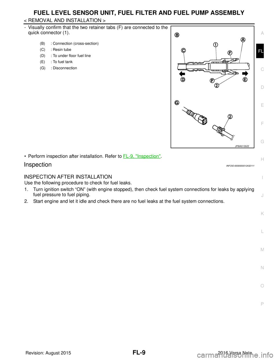
- Visually confirm that the two retainer tabs (F) are connected to the
quick connector (1).
• Perform inspection after installation. Refer to FL-9, "
Inspection".
InspectionINFOID:0000000012432111
INSPECTION AFTER INSTALLATION
Use the following procedure to check for fuel leaks.
1. Turn ignition switch “ON” (with engine stopped), then check fuel system connections for leaks by applying
fuel pressure to fuel piping.
2. Start engine and let it idle and check there are no fuel leaks at the fuel system connections.
(B) : Connection (cross-section)
(C) : Resin tube
(D) : To under floor fuel line
(E) : To fuel tank
(G) : Disconnection
JPBIA0130ZZ
Revision: August 2015 2016 Versa Note
cardiagn.com
Page 1876 of 3641
FL-10
< REMOVAL AND INSTALLATION >
FUEL TANK
FUEL TANK
Exploded ViewINFOID:0000000012432112
Removal and InstallationINFOID:0000000012432113
WARNING:
Read “General Precautions” when working on the fuel system. Refer to FL-2, "
General Precaution".
NOTE:
When removing components such as hoses, tubes/lines, etc. , cap or plug openings to prevent fluid from spill-
ing.
REMOVAL
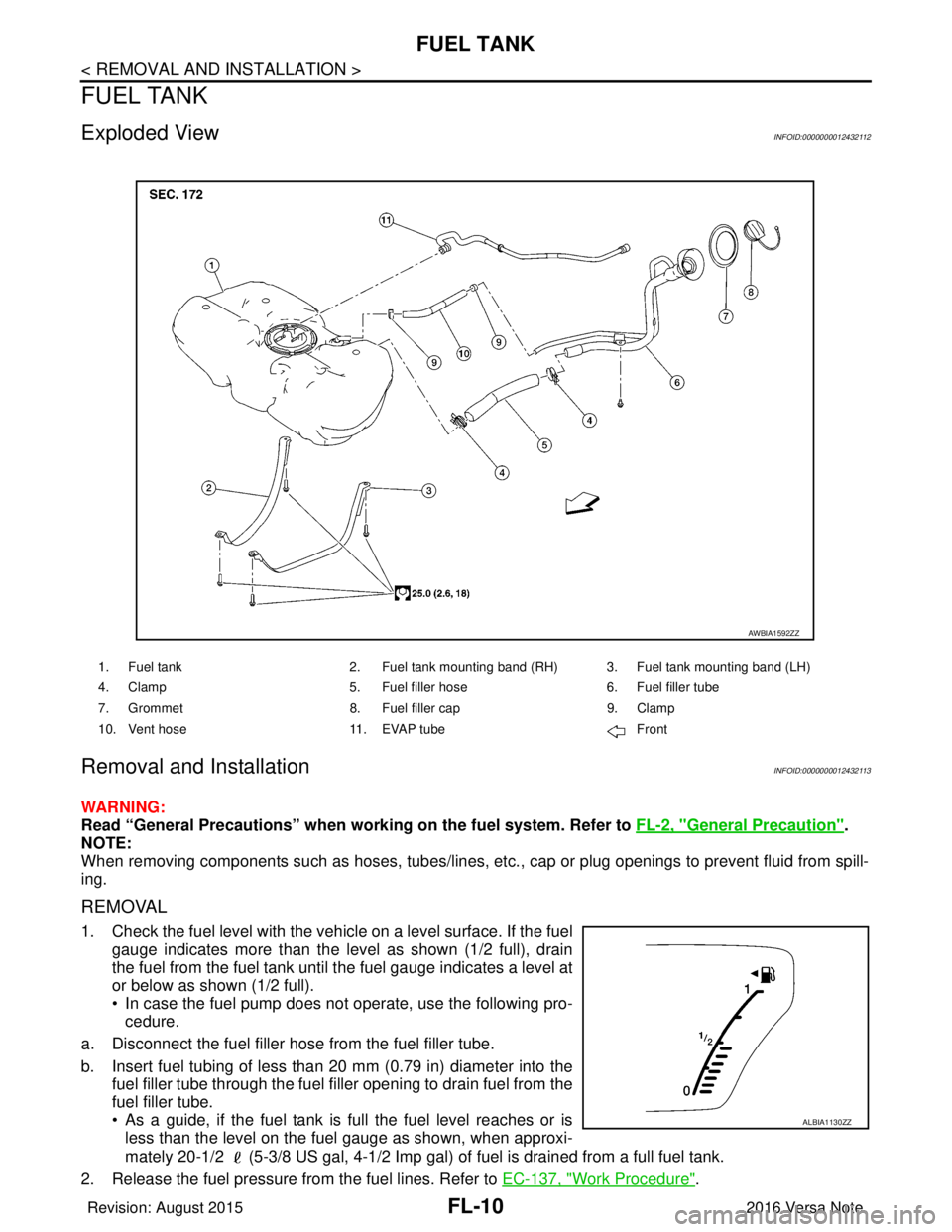
1. Check the fuel level with the vehicle on a level surface. If the fuel gauge indicates more than the level as shown (1/2 full), drain
the fuel from the fuel tank until the fuel gauge indicates a level at
or below as shown (1/2 full).
• In case the fuel pump does not operate, use the following pro-cedure.
a. Disconnect the fuel filler hose from the fuel filler tube.
b. Insert fuel tubing of less than 20 mm (0.79 in) diameter into the fuel filler tube through the fuel f iller opening to drain fuel from the
fuel filler tube.
• As a guide, if the fuel tank is full the fuel level reaches or is less than the level on the fuel gauge as shown, when approxi-
mately 20-1/2 (5-3/8 US gal, 4-1/2 Imp gal) of fuel is drained from a full fuel tank.
2. Release the fuel pressure from the fuel lines. Refer to EC-137, "
Work Procedure".
1. Fuel tank2. Fuel tank mounting band (RH) 3. Fuel tank mounting band (LH)
4. Clamp 5. Fuel filler hose 6. Fuel filler tube
7. Grommet 8. Fuel filler cap 9. Clamp
10. Vent hose 11. EVAP tube Front
AWBIA1592ZZ
ALBIA1130ZZ
Revision: August 2015 2016 Versa Note
cardiagn.com
Page 1877 of 3641
FUEL TANKFL-11
< REMOVAL AND INSTALLATION >
C
DE
F
G H
I
J
K L
M A
FL
NP
O
3. Open fuel filler lid.
4. Open fuel filler cap and release
the pressure inside fuel tank.
5. Remove the rear seat cushion. Refer to SE-26, "
SEAT CUSHION : Removal and Installation".
6. Remove the inspection hole cover. NOTE:
Inspection hole cover is held by an adhesive.
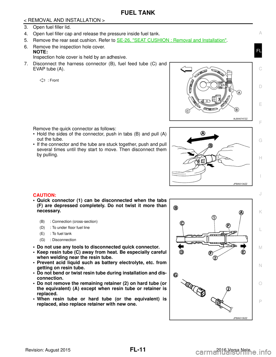
7. Disconnect the harness connector (B), fuel feed tube (C) and
EVAP tube (A).
Remove the quick connector as follows:
• Hold the sides of the connector, push in tabs (B) and pull (A) out the tube.
• If the connector and the tube are stuck together, push and pull several times until they start to move. Then disconnect them
by pulling.
CAUTION:
• Quick connector (1) can be disconnected when the tabs (F) are depressed completely. Do not twist it more than
necessary.
• Do not use any tools to disconnected quick connector.
• Keep resin tube (C) away from heat. Be especially careful when welding near the resin tube.
• Prevent acid liquid such as battery electrolyte, etc. from getting on resin tube.
• Do not bend or twist resin tube during installation and dis- connection.
• Do not remove the remaining retainer (2) on hard tube (or the equivalent) (A) except when resin tube or retainer is
replaced.
• When resin tube or hard tube (or the equivalent) is replaced, also replace retainer with new one.
: Front
ALBIA0747ZZ
JPBIA0134ZZ
(B) : Connection (cross-section)
(D) : To under floor fuel line
(E) : To fuel tank
(G) : Disconnection
JPBIA0130ZZ
Revision: August 2015 2016 Versa Note
cardiagn.com
Page 1878 of 3641
FL-12
< REMOVAL AND INSTALLATION >
FUEL TANK
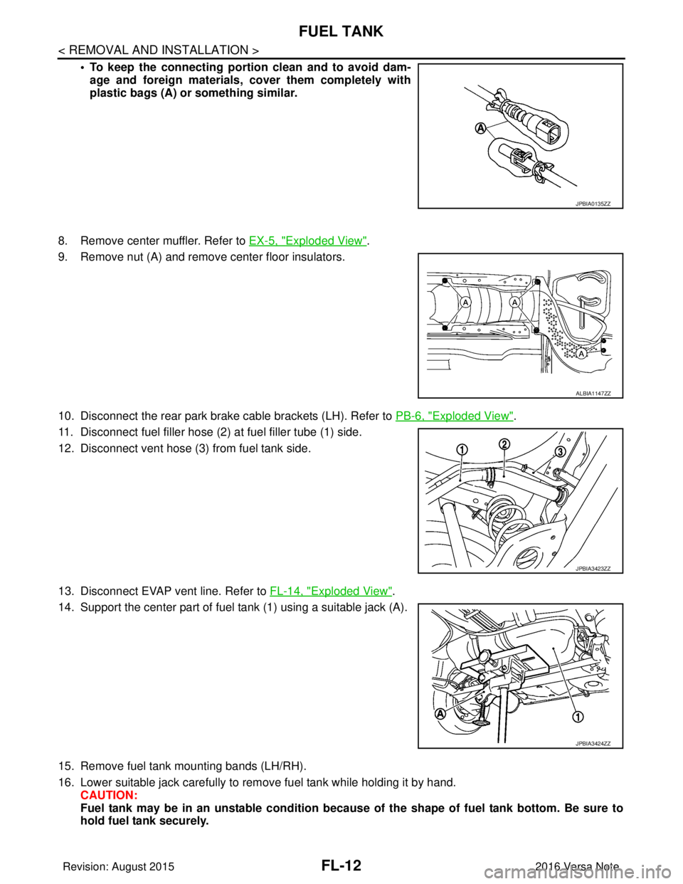
• To keep the connecting portion clean and to avoid dam-
age and foreign materials, cover them completely with
plastic bags (A) or something similar.
8. Remove center muffler. Refer to EX-5, "
Exploded View".
9. Remove nut (A) and remove center floor insulators.
10. Disconnect the rear park brake cable brackets (LH). Refer to PB-6, "
Exploded View".
11. Disconnect fuel filler hose (2) at fuel filler tube (1) side.
12. Disconnect vent hose (3) from fuel tank side.
13. Disconnect EVAP vent line. Refer to FL-14, "
Exploded View".
14. Support the center part of fuel tank (1) using a suitable jack (A).
15. Remove fuel tank mounting bands (LH/RH).
16. Lower suitable jack carefully to remove fuel tank while holding it by hand. CAUTION:
Fuel tank may be in an unstable condition because of the shape of fuel tank bottom. Be sure to
hold fuel tank securely.
JPBIA0135ZZ
ALBIA1147ZZ
JPBIA3423ZZ
JPBIA3424ZZ
Revision: August 2015 2016 Versa Note
cardiagn.com
Page 1879 of 3641
FUEL TANKFL-13
< REMOVAL AND INSTALLATION >
C
DE
F
G H
I
J
K L
M A
FL
NP
O
17. If replacing the fuel tank, remove the fuel level sensor unit, fuel filter and fuel pump assembly to transfer to
the new fuel tank.
CAUTION:
Do not reuse O-ring.
INSTALLATION
Installation is in the reverse order of removal.
Fuel Filler Hose
• Insert fuel filler hose to the length below.
• Be sure hose clamp is not placed on swelled area of fuel filler tube.
• Install fuel filler hose to fuel t ank, paying attention to install mark.
EVAP Hose
1. Check connections for damage or foreign material.
2. Align the matching side connection part with the center of shaft, and insert connector straight until a "click"
sound is heard.
InspectionINFOID:0000000012432114
INSPECTION AFTER INSTALLATION
Use the following procedure to check for fuel leaks.
1. Turn ignition switch “ON” (with engine stopped), then check fuel system connections for leaks by applying
fuel pressure to fuel piping.
2. Start engine and let it idle and check there are no fuel leaks at the fuel system connections.
Fuel filler hose : 35 mm (1.38 in)
Vent hose : 25 mm (0.98 in)
Revision: August 2015
2016 Versa Note
cardiagn.com
Page 1887 of 3641
FUEL LEVEL SENSOR UNITFL-21
< DISASSEMBLY AND ASSEMBLY >
C
DE
F
G H
I
J
K L
M A
FL
NP
O
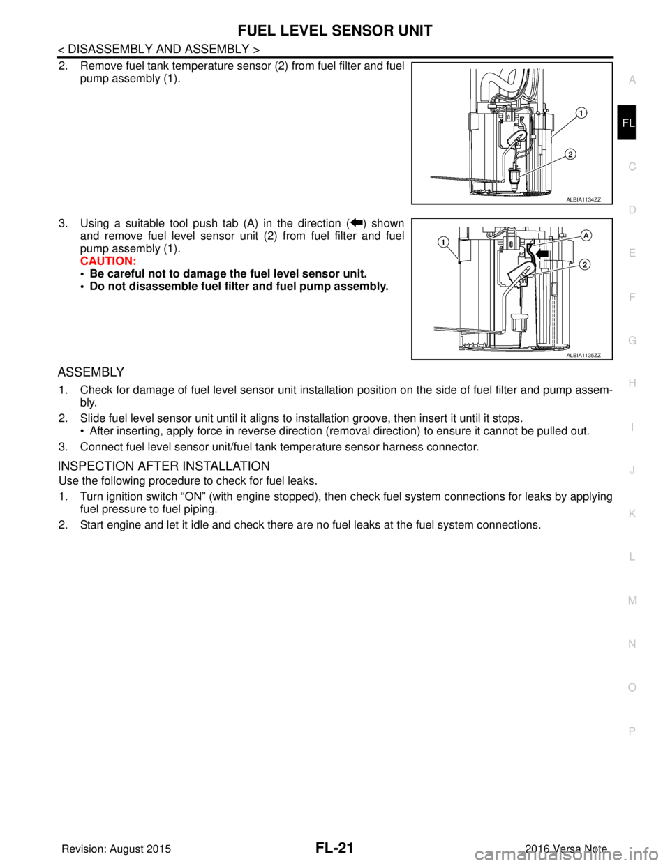
2. Remove fuel tank temperature s
ensor (2) from fuel filter and fuel
pump assembly (1).
3. Using a suitable tool push tab (A) in the direction ( ) shown and remove fuel level sensor unit (2) from fuel filter and fuel
pump assembly (1).
CAUTION:
• Be careful not to damage the fuel level sensor unit.
• Do not disassemble fuel filter and fuel pump assembly.
ASSEMBLY
1. Check for damage of fuel level sensor unit installation position on the side of fuel filter and pump assem- bly.
2. Slide fuel level sensor unit until it aligns to installation groove, then insert it until it stops. • After inserting, apply force in reverse direction (removal direction) to ensure it cannot be pulled out.
3. Connect fuel level sensor unit/fuel t ank temperature sensor harness connector.
INSPECTION AFTER INSTALLATION
Use the following procedure to check for fuel leaks.
1. Turn ignition switch “ON” (with engine stopped), then check fuel system connections for leaks by applying
fuel pressure to fuel piping.
2. Start engine and let it idle and check there are no fuel leaks at the fuel system connections.
ALBIA1134ZZ
ALBIA1135ZZ
Revision: August 2015 2016 Versa Note
cardiagn.com
Page 2333 of 3641
MA-18
< PERIODIC MAINTENANCE >
ENGINE MAINTENANCE
ENGINE COOLANT : Flushing Cooling System
INFOID:0000000012432255
1. Install radiator drain plug and reservoir tank, if removed.
CAUTION:
Be sure to clean drain plug and install with new O-ring.
2. If water drain plugs on cylinder block were removed, close and tighten them. Refer to EM-93, "
Exploded
View".
3. Remove air duct from between air cleaner case and electric throttle control actuator. Refer to EM-26,
"Removal and Installation".
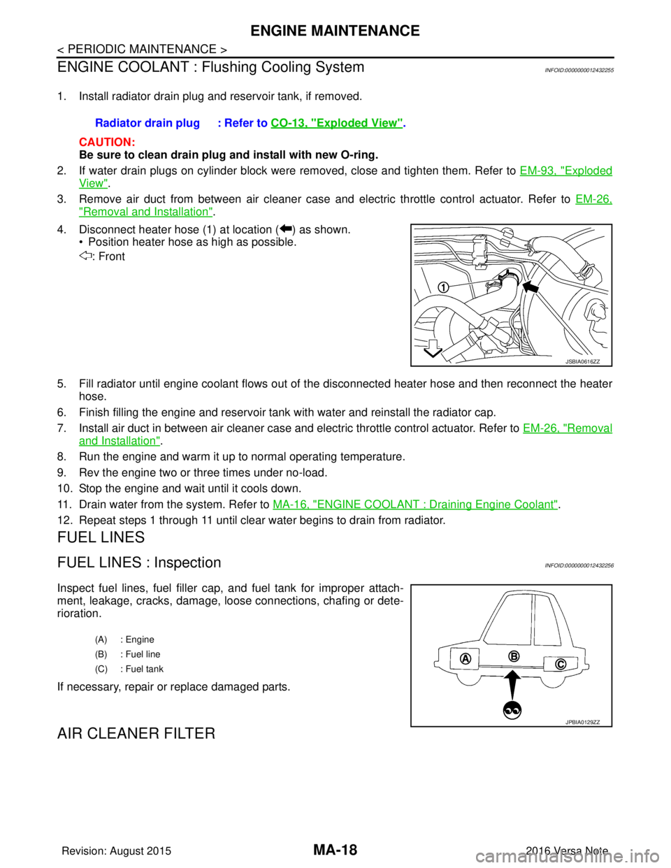
4. Disconnect heater hose (1) at location ( ) as shown. • Position heater hose as high as possible.
: Front
5. Fill radiator until engine coolant flows out of the disconnected heater hose and then reconnect the heater
hose.
6. Finish filling the engine and reservoir tank with water and reinstall the radiator cap.
7. Install air duct in between air cleaner case and electric throttle control actuator. Refer to EM-26, "
Removal
and Installation".
8. Run the engine and warm it up to normal operating temperature.
9. Rev the engine two or three times under no-load.
10. Stop the engine and wait until it cools down.
11. Drain water from the system. Refer to MA-16, "
ENGINE COOLANT : Draining Engine Coolant".
12. Repeat steps 1 through 11 until clear water begins to drain from radiator.
FUEL LINES
FUEL LINES : InspectionINFOID:0000000012432256
Inspect fuel lines, fuel filler cap, and fuel tank for improper attach-
ment, leakage, cracks, damage, l oose connections, chafing or dete-
rioration.
If necessary, repair or replace damaged parts.
AIR CLEANER FILTER
Radiator drain plug : Refer to CO-13, "Exploded View".
JSBIA0616ZZ
(A) : Engine
(B) : Fuel line
(C) : Fuel tank
JPBIA0129ZZ
Revision: August 2015 2016 Versa Note
cardiagn.com
Page 2403 of 3641
![NISSAN NOTE 2016 Service Repair Manual MWI
FUEL LEVEL SENSOR SIGNAL CIRCUITMWI-45
< DTC/CIRCUIT DIAGNOSIS > [TYPE A]
C
D
E
F
G H
I
J
K L
M B A
O P
FUEL LEVEL SENSOR SIGNAL CIRCUIT
DescriptionINFOID:0000000012432576
The fuel level sensor un](/manual-img/5/57363/w960_57363-2402.png "NISSAN NOTE 2016 Service Repair Manual MWI
FUEL LEVEL SENSOR SIGNAL CIRCUITMWI-45
< DTC/CIRCUIT DIAGNOSIS > [TYPE A]
C
D
E
F
G H
I
J
K L
M B A
O P
FUEL LEVEL SENSOR SIGNAL CIRCUIT
DescriptionINFOID:0000000012432576
The fuel level sensor un")
MWI
FUEL LEVEL SENSOR SIGNAL CIRCUITMWI-45
< DTC/CIRCUIT DIAGNOSIS > [TYPE A]
C
D
E
F
G H
I
J
K L
M B A
O P
FUEL LEVEL SENSOR SIGNAL CIRCUIT
DescriptionINFOID:0000000012432576
The fuel level sensor unit and fuel pump detects the approx imate fuel level in the fuel tank and transmits the
fuel level signal to the combination meter.
Component Function CheckINFOID:0000000012432577
1.COMBINATION METER INPUT SIGNAL
1. Select METER/M&A on CONSULT.
2. Using FUEL METER of DATA MONITOR, compare the DATA MONITOR value with the fuel gauge posi- tion.
Does monitor value match fuel gauge reading?
YES >> Inspection End.
NO >> Replace combination meter. Refer to MWI-54, "
Removal and Installation".
Diagnosis ProcedureINFOID:0000000012432578
Regarding Wiring Diagram information, refer to MWI-26, "Wiring Diagram".
1.CHECK HARNESS CONNECTOR
1. Turn ignition switch OFF.
2. Check combination meter and fuel level sensor unit terminals (meter-side and harness-side) for poor con- nection.
Is the inspection result normal?
YES >> GO TO 2.
NO >> Repair or replace terminals or connectors.
2.CHECK FUEL LEVEL SENSOR UNIT CIRCUIT
1. Disconnect combination meter harness connector M82 and fuel level sensor unit and fuel pump harness
connector B44.
2. Check continuity between combination meter harness connector M82 terminal 6 and fuel level sensor unit
and fuel pump harness connector B44 terminal 2.
3. Check continuity between fuel level sensor unit and fuel pump harness connector B44 terminal 2 and ground.
Is the inspection result normal?
YES >> GO TO 3.
NO >> Repair harness or connector.
Fuel gauge indication position Reference value of data monitor [L]
1A pp ro x. 3 9.8
3/4 Approx. 31.2
1/2 Approx. 20.8
1/4 Approx. 10.8
0A ppro x. 2 .9
Connector TerminalConnector Terminal Continuity
M82 6B44 2Yes
Connector Terminal
GroundContinuity
B44 2 No
Revision: August 2015 2016 Versa Note
cardiagn.com