2016 NISSAN NOTE charging
[x] Cancel search: chargingPage 618 of 3641
CHG
B TERMINAL CIRCUITCHG-23
< DTC/CIRCUIT DIAGNOSIS >
C
DE
F
G H
I
J
K L
B A
O P
N
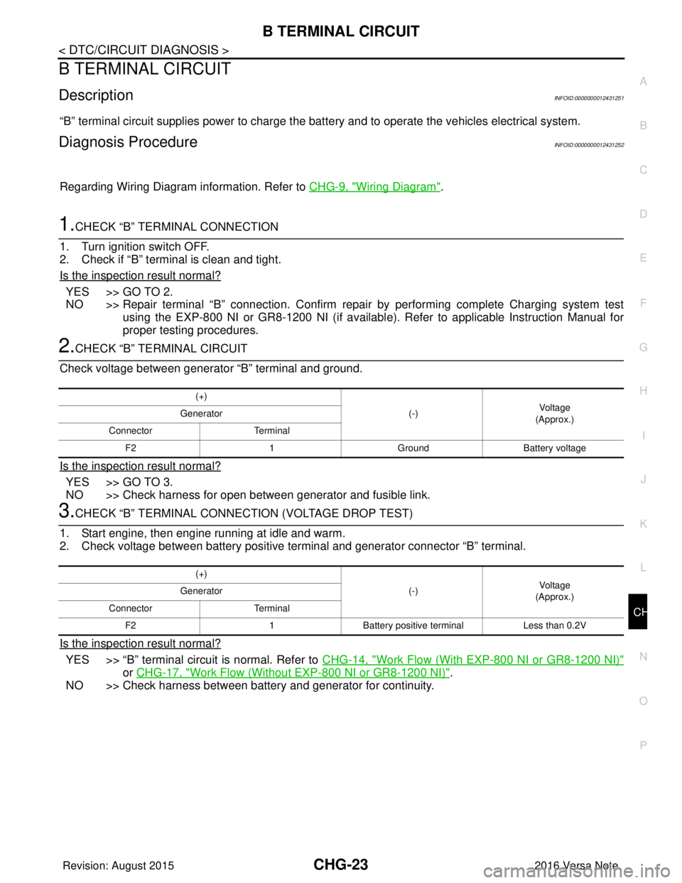
B TERMINAL CIRCUIT
DescriptionINFOID:0000000012431251
“B” terminal circuit supplies power to charge the batte
ry and to operate the vehicles electrical system.
Diagnosis ProcedureINFOID:0000000012431252
Regarding Wiring Diagram information. Refer to CHG-9, "Wiring Diagram".
1.CHECK “B” TERMINAL CONNECTION
1. Turn ignition switch OFF.
2. Check if “B” terminal is clean and tight.
Is the inspection result normal?
YES >> GO TO 2.
NO >> Repair terminal “B” connection. Confirm repair by performing complete Charging system test using the EXP-800 NI or GR8-1200 NI (if availabl e). Refer to applicable Instruction Manual for
proper testing procedures.
2.CHECK “B” TERMINAL CIRCUIT
Check voltage between generator “B” terminal and ground.
Is the inspection result normal?
YES >> GO TO 3.
NO >> Check harness for open between generator and fusible link.
3.CHECK “B” TERMINAL CONNECT ION (VOLTAGE DROP TEST)
1. Start engine, then engine running at idle and warm.
2. Check voltage between battery positive te rminal and generator connector “B” terminal.
Is the inspection result normal?
YES >> “B” terminal circuit is normal. Refer to CHG-14, "Work Flow (With EXP-800 NI or GR8-1200 NI)"
or CHG-17, "Work Flow (Without EXP-800 NI or GR8-1200 NI)".
NO >> Check harness between battery and generator for continuity.
(+)
(-)Voltage
(Approx.)
Generator
Connector Terminal
F2 1GroundBattery voltage
(+)
(-)Voltage
(Approx.)
Generator
Connector Terminal
F2 1Battery positive terminal Less than 0.2V
Revision: August 2015 2016 Versa Note
cardiagn.com
Page 619 of 3641
CHG-24
< DTC/CIRCUIT DIAGNOSIS >
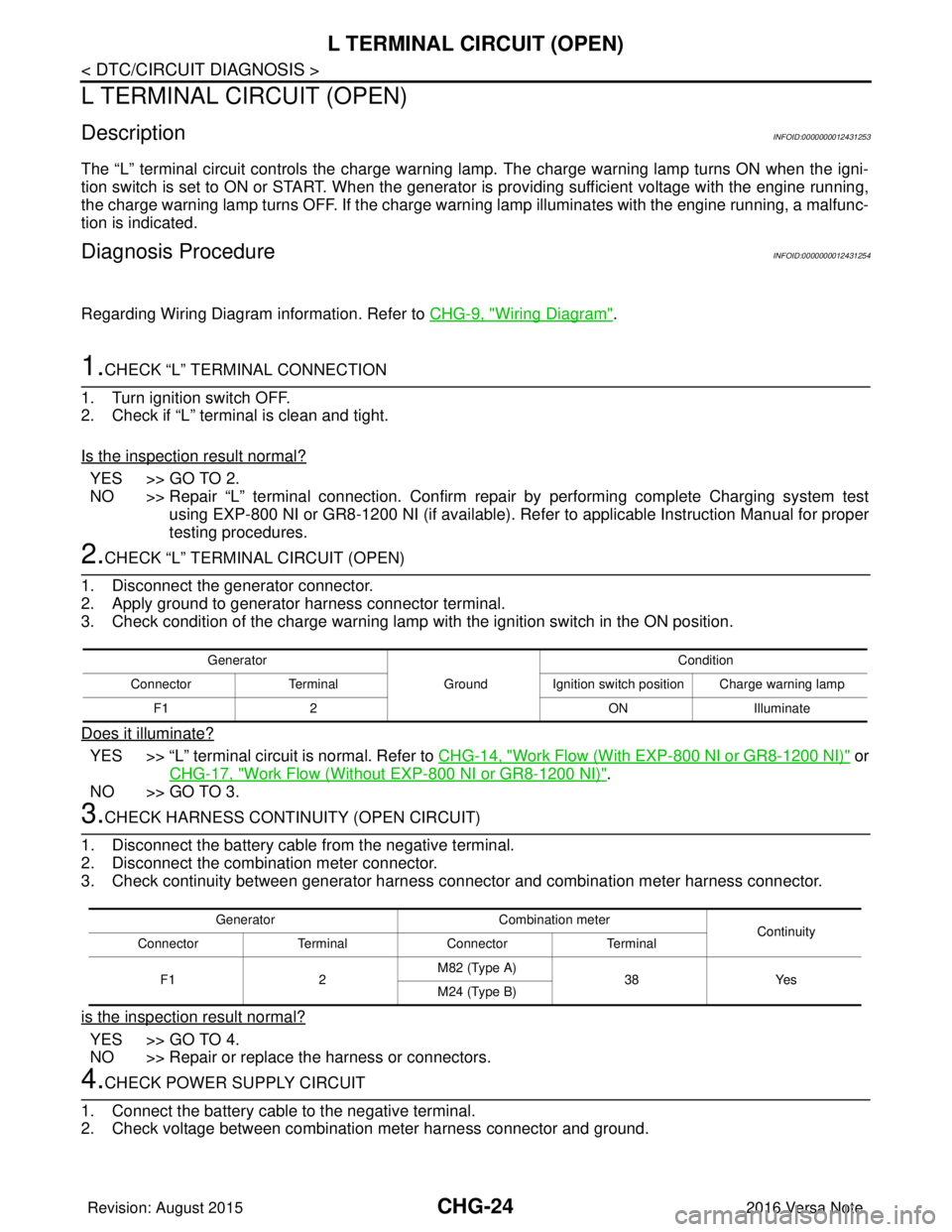
L TERMINAL CIRCUIT (OPEN)
L TERMINAL CIRCUIT (OPEN)
DescriptionINFOID:0000000012431253
The “L” terminal circuit controls the charge warning lamp. The charge warning lamp turns ON when the igni-
tion switch is set to ON or START. When the generator is providing sufficient voltage with the engine running,
the charge warning lamp turns OFF. If the charge warn ing lamp illuminates with the engine running, a malfunc-
tion is indicated.
Diagnosis ProcedureINFOID:0000000012431254
Regarding Wiring Diagram information. Refer to CHG-9, "Wiring Diagram".
1.CHECK “L” TERMINAL CONNECTION
1. Turn ignition switch OFF.
2. Check if “L” terminal is clean and tight.
Is the inspection result normal?
YES >> GO TO 2.
NO >> Repair “L” terminal connection. Confirm repa ir by performing complete Charging system test
using EXP-800 NI or GR8-1200 NI (if available). Refer to applicable Instruction Manual for proper
testing procedures.
2.CHECK “L” TERMIN AL CIRCUIT (OPEN)
1. Disconnect the generator connector.
2. Apply ground to generator harness connector terminal.
3. Check condition of the charge warning lamp with the ignition switch in the ON position.
Does it illuminate?
YES >> “L” terminal circuit is normal. Refer to CHG-14, "Work Flow (With EXP-800 NI or GR8-1200 NI)" or
CHG-17, "
Work Flow (Without EXP-800 NI or GR8-1200 NI)".
NO >> GO TO 3.
3.CHECK HARNESS CONTI NUITY (OPEN CIRCUIT)
1. Disconnect the battery cable from the negative terminal.
2. Disconnect the combination meter connector.
3. Check continuity between generator harness c onnector and combination meter harness connector.
is the inspection result normal?
YES >> GO TO 4.
NO >> Repair or replace the harness or connectors.
4.CHECK POWER SUPPLY CIRCUIT
1. Connect the battery cable to the negative terminal.
2. Check voltage between combination meter harness connector and ground.
Generator
GroundCondition
Connector Terminal Ignition switch position Charge warning lamp
F1 2 ONIlluminate
Generator Combination meter
Continuity
Connector TerminalConnector Terminal
F1 2M82 (Type A)
38Yes
M24 (Type B)
Revision: August 2015 2016 Versa Note
cardiagn.com
Page 622 of 3641
CHG
S TERMINAL CIRCUITCHG-27
< DTC/CIRCUIT DIAGNOSIS >
C
DE
F
G H
I
J
K L
B A
O P
N
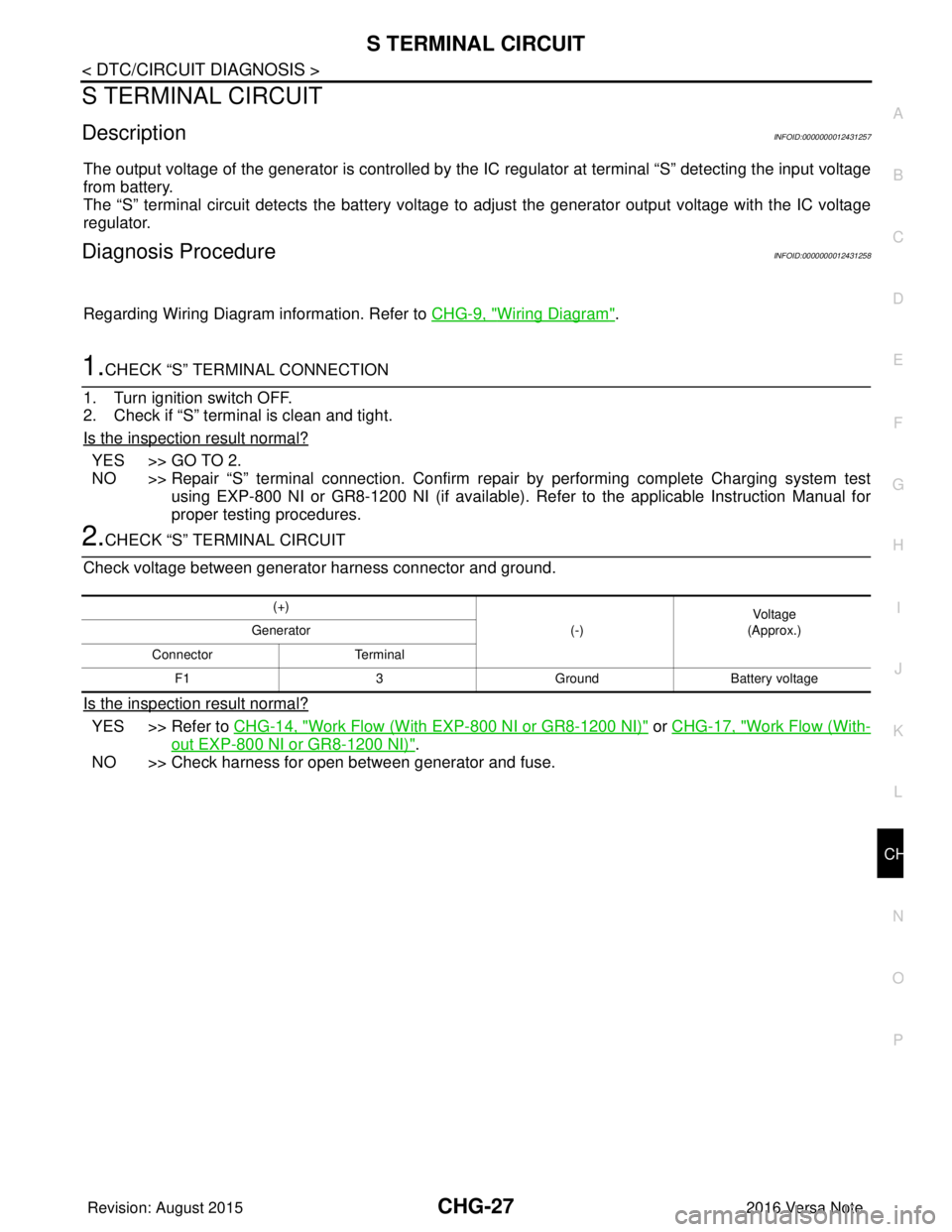
S TERMINAL CIRCUIT
DescriptionINFOID:0000000012431257
The output voltage of the generator is controlled by the IC
regulator at terminal “S” detecting the input voltage
from battery.
The “S” terminal circuit detects the battery voltage to adjust the generator output voltage with the IC voltage
regulator.
Diagnosis ProcedureINFOID:0000000012431258
Regarding Wiring Diagram information. Refer to CHG-9, "Wiring Diagram".
1.CHECK “S” TERMINAL CONNECTION
1. Turn ignition switch OFF.
2. Check if “S” terminal is clean and tight.
Is the inspection result normal?
YES >> GO TO 2.
NO >> Repair “S” terminal connection. Confirm repair by performing complete Charging system test using EXP-800 NI or GR8-1200 NI (if available). Refer to the applicable Instruction Manual for
proper testing procedures.
2.CHECK “S” TERMINAL CIRCUIT
Check voltage between generator harness connector and ground.
Is the inspection result normal?
YES >> Refer to CHG-14, "Work Flow (With EXP-800 NI or GR8-1200 NI)" or CHG-17, "Work Flow (With-
out EXP-800 NI or GR8-1200 NI)".
NO >> Check harness for open between generator and fuse.
(+)
(-)Voltage
(Approx.)
Generator
Connector Terminal F1 3GroundBattery voltage
Revision: August 2015 2016 Versa Note
cardiagn.com
Page 623 of 3641
CHG-28
< SYMPTOM DIAGNOSIS >
CHARGING SYSTEM
SYMPTOM DIAGNOSIS
CHARGING SYSTEM
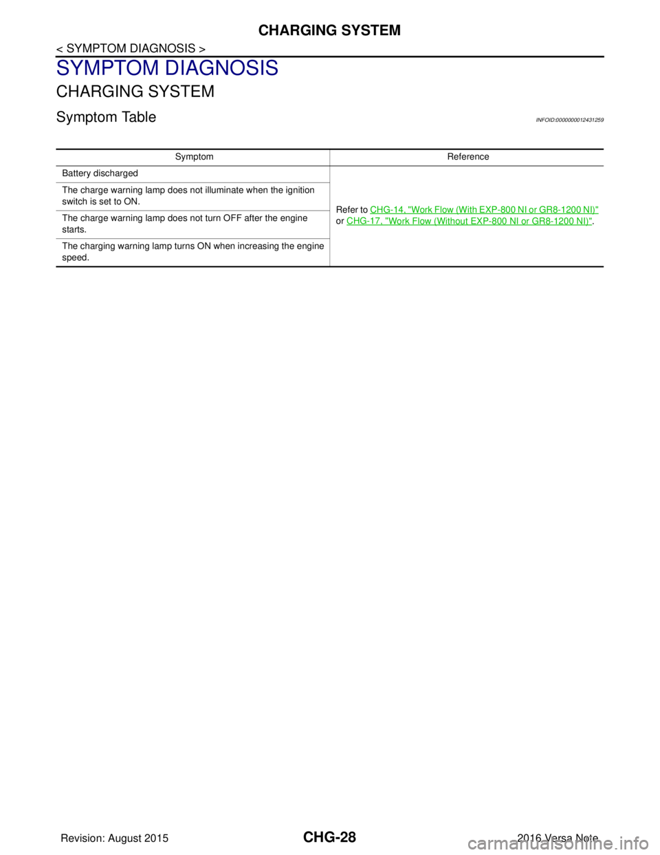
Symptom TableINFOID:0000000012431259
SymptomReference
Battery discharged
Refer to CHG-14, "
Work Flow (With EXP-800 NI or GR8-1200 NI)"
or CHG-17, "
Work Flow (Without EXP-800 NI or GR8-1200 NI)".
The charge warning lamp does not illuminate when the ignition
switch is set to ON.
The charge warning lamp does not turn OFF after the engine
starts.
The charging warning lamp turns ON when increasing the engine
speed.
Revision: August 2015
2016 Versa Note
cardiagn.com
Page 1150 of 3641
![NISSAN NOTE 2016 Service Repair Manual COMPONENT PARTSEC-23
< SYSTEM DESCRIPTION > [HR16DE]
C
D
E
F
G H
I
J
K L
M A
EC
NP
O
Exhaust Valve Timing Control Solenoid ValveINFOID:0000000012431286
Exhaust valve timing control solenoi
d valve is](/manual-img/5/57363/w960_57363-1149.png "NISSAN NOTE 2016 Service Repair Manual COMPONENT PARTSEC-23
< SYSTEM DESCRIPTION > [HR16DE]
C
D
E
F
G H
I
J
K L
M A
EC
NP
O
Exhaust Valve Timing Control Solenoid ValveINFOID:0000000012431286
Exhaust valve timing control solenoi
d valve is")
COMPONENT PARTSEC-23
< SYSTEM DESCRIPTION > [HR16DE]
C
D
E
F
G H
I
J
K L
M A
EC
NP
O
Exhaust Valve Timing Control Solenoid ValveINFOID:0000000012431286
Exhaust valve timing control solenoi
d valve is activated by ON/OFF
pulse duty (ratio) signals from the ECM.
The exhaust valve timing control solenoid valve changes the oil
amount and direction of flow through exhaust valve timing control
unit or stops oil flow.
The longer pulse width retards valve angle.
The shorter pulse width advances valve angle.
When ON and OFF pulse widths become equal, the solenoid valve
stops oil pressure flow to fix the exhaust valve angle at the control
position.
Fuel InjectorINFOID:0000000012431287
The fuel injector is a small, precise solenoid valve. When the ECM
supplies a ground to the fuel injector circuit, the coil in the fuel injec-
tor is energized. The energized coil pulls the ball valve back and
allows fuel to flow through the fuel injector into the intake manifold.
The amount of fuel injected depends upon the injection pulse dura-
tion. Pulse duration is the length of time the fuel injector remains
open. The ECM controls the injection pulse duration based on
engine fuel needs.
Fuel PumpINFOID:0000000012431288
*: ECM determines the start signal status by the signals of engine speed and battery voltage.
The ECM activates the fuel pump for a few seconds after the ignition switch is turned ON to improve engine
start ability. If the ECM receives a engine speed signal from the crankshaft position sensor (POS) and cam-
shaft position sensor (PHASE), it knows that the engi ne is rotating, and causes the pump to operate. If the
engine speed signal is not received when the ignition s witch is ON, the engine stalls. The ECM stops pump
operation and prevents battery discharging, thereby improving safety. The EC M does not directly drive the fuel
pump. It controls the ON/OFF fuel pump rela y, which in turn controls the fuel pump.
JSBIA0652ZZ
JSBIA0742ZZ
SensorInput signal to ECMECM functionActuator
Crankshaft position sensor (POS)
Camshaft position sensor (PHASE) Engine speed*
Fuel pump controlFuel pump relay
↓
Fuel pump
Battery Battery voltage*
Condition Fuel pump operation
Ignition switch is turned to ON. Operates for 1 second.
Engine running and cranking Operates.
When engine is stopped Stops in 1.5 seconds.
Except as shown above Sto ps .
Revision: August 20152016 Versa Note
cardiagn.com
Page 1152 of 3641
![NISSAN NOTE 2016 Service Repair Manual COMPONENT PARTSEC-25
< SYSTEM DESCRIPTION > [HR16DE]
C
D
E
F
G H
I
J
K L
M A
EC
NP
O
<Reference data>
*: These data are reference values and are measured between ECM terminals.
Intake Valve Timing Con](/manual-img/5/57363/w960_57363-1151.png "NISSAN NOTE 2016 Service Repair Manual COMPONENT PARTSEC-25
< SYSTEM DESCRIPTION > [HR16DE]
C
D
E
F
G H
I
J
K L
M A
EC
NP
O
<Reference data>
*: These data are reference values and are measured between ECM terminals.
Intake Valve Timing Con")
COMPONENT PARTSEC-25
< SYSTEM DESCRIPTION > [HR16DE]
C
D
E
F
G H
I
J
K L
M A
EC
NP
O
*: These data are reference values and are measured between ECM terminals.
Intake Valve Timing Control Solenoid ValveINFOID:0000000012431293
Intake valve timing control solenoid valve is activated by ON/OFF
pulse duty (ratio) signals from the ECM.
The intake valve timing control solenoid valve changes the oil
amount and direction of flow through intake valve timing control unit
or stops oil flow.
The longer pulse width advances valve angle.
The shorter pulse width retards valve angle.
When ON and OFF pulse widths become equal, the solenoid valve
stops oil pressure flow to fix the intake valve angle at the control
position.
Knock SensorINFOID:0000000012431294
The knock sensor is attached to t
he cylinder block. It senses engine
knocking using a piezoelectric el ement. A knocking vibration from
the cylinder block is sensed as vibrational pressure. This pressure is
converted into a voltage signal and sent to the ECM.
Battery Current Sensor (With Battery Temperature Sensor)INFOID:0000000012431295
OUTLINE
The power generation voltage variable control enables fuel con-
sumption to be decreased by reducing the engine load which is
caused by the power generation of the generator.
Based on sensor signals, ECM judges whether or not the power
generation voltage variable contro l is performed. When performing
the power generation voltage variable control, ECM calculates the
target power generation voltage based on the sensor signal. And
ECM sends the calculated value as the power generation command
value to IPDM E/R. For the details of the power generation voltage
variable control, refer to CHG-8, "
System Description".
CAUTION:
Never connect the electrical co mponent or the ground wire
directly to the battery terminal. The connection cau ses the malfunction of the power generation volt-
age variable control, and then the battery discharge may occur.
BATTERY CURRENT SENSOR
The battery current sensor is installed to the battery negative cable. The sensor measures the charging/dis-
charging current of the battery.
Intake air temperature [ °C ( °F)] Voltage* (V) Resistance (k Ω)
25 (77) 3.31.800 - 2.200
80 (176) 1.20.283 - 0.359
SEF012P
PBIB1842E
JSBIA0284ZZ
JPBIA3262ZZ
Revision: August 2015 2016 Versa Note
cardiagn.com
Page 1834 of 3641
FRONT DRIVE SHAFT BOOTFAX-17
< REMOVAL AND INSTALLATION >
CEF
G H
I
J
K L
M A
B
FA X
N
O P
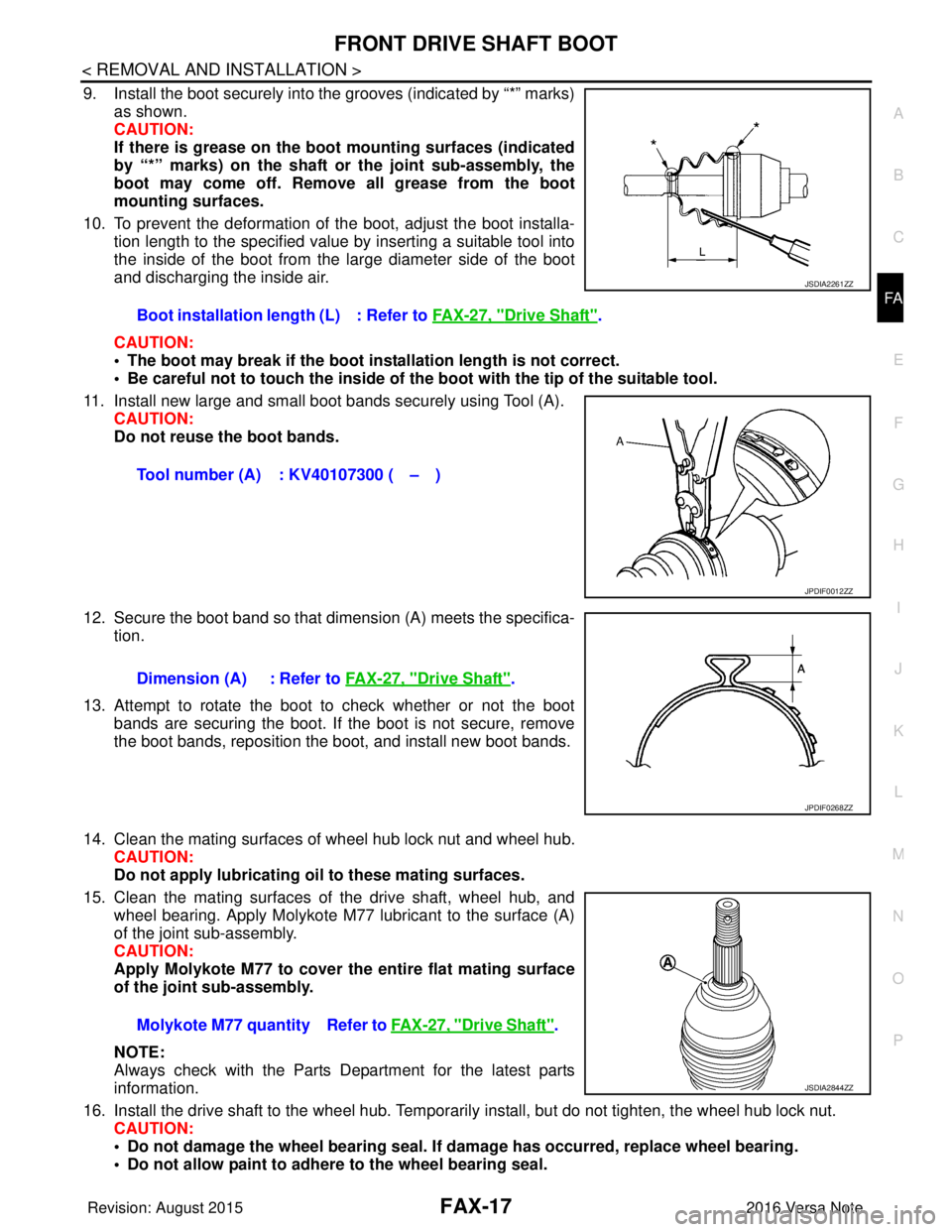
9. Install the boot securely into the grooves (indicated by “*” marks) as shown.
CAUTION:
If there is grease on the bo ot mounting surfaces (indicated
by “*” marks) on the shaft or the joint sub-assembly, the
boot may come off. Remo ve all grease from the boot
mounting surfaces.
10. To prevent the deformation of the boot, adjust the boot installa- tion length to the specified value by inserting a suitable tool into
the inside of the boot from the large diameter side of the boot
and discharging the inside air.
CAUTION:
• The boot may break if the boot in stallation length is not correct.
• Be careful not to touch the inside of the boot with the tip of the suitable tool.
11. Install new large and small boot bands securely using Tool (A). CAUTION:
Do not reuse the boot bands.
12. Secure the boot band so that dimension (A) meets the specifica- tion.
13. Attempt to rotate the boot to check whether or not the boot bands are securing the boot. If the boot is not secure, remove
the boot bands, reposition the boot, and install new boot bands.
14. Clean the mating surfaces of wheel hub lock nut and wheel hub. CAUTION:
Do not apply lubricating oil to these mating surfaces.
15. Clean the mating surfaces of the drive shaft, wheel hub, and wheel bearing. Apply Molykote M77 lubricant to the surface (A)
of the joint sub-assembly.
CAUTION:
Apply Molykote M77 to cover the entire flat mating surface
of the joint sub-assembly.
NOTE:
Always check with the Parts Department for the latest parts
information.
16. Install the drive shaft to the wheel hub. Temporaril y install, but do not tighten, the wheel hub lock nut.
CAUTION:
• Do not damage the wheel bearing seal. If damage has occurred, replace wheel bearing.
• Do not allow paint to adhere to the wheel bearing seal.
Boot installation length (L) : Refer to
FAX-27, "
Drive Shaft".
Tool number (A) : KV40107300 ( – )
JSDIA2261ZZ
JPDIF0012ZZ
Dimension (A) : Refer to FAX-27, "Drive Shaft".
JPDIF0268ZZ
Molykote M77 quantity Refer to FAX-27, "Drive Shaft".
JSDIA2844ZZ
Revision: August 2015 2016 Versa Note
cardiagn.com
Page 1841 of 3641
FAX-24
< UNIT DISASSEMBLY AND ASSEMBLY >
FRONT DRIVE SHAFT
Always check with the Parts Department for the latest parts information.
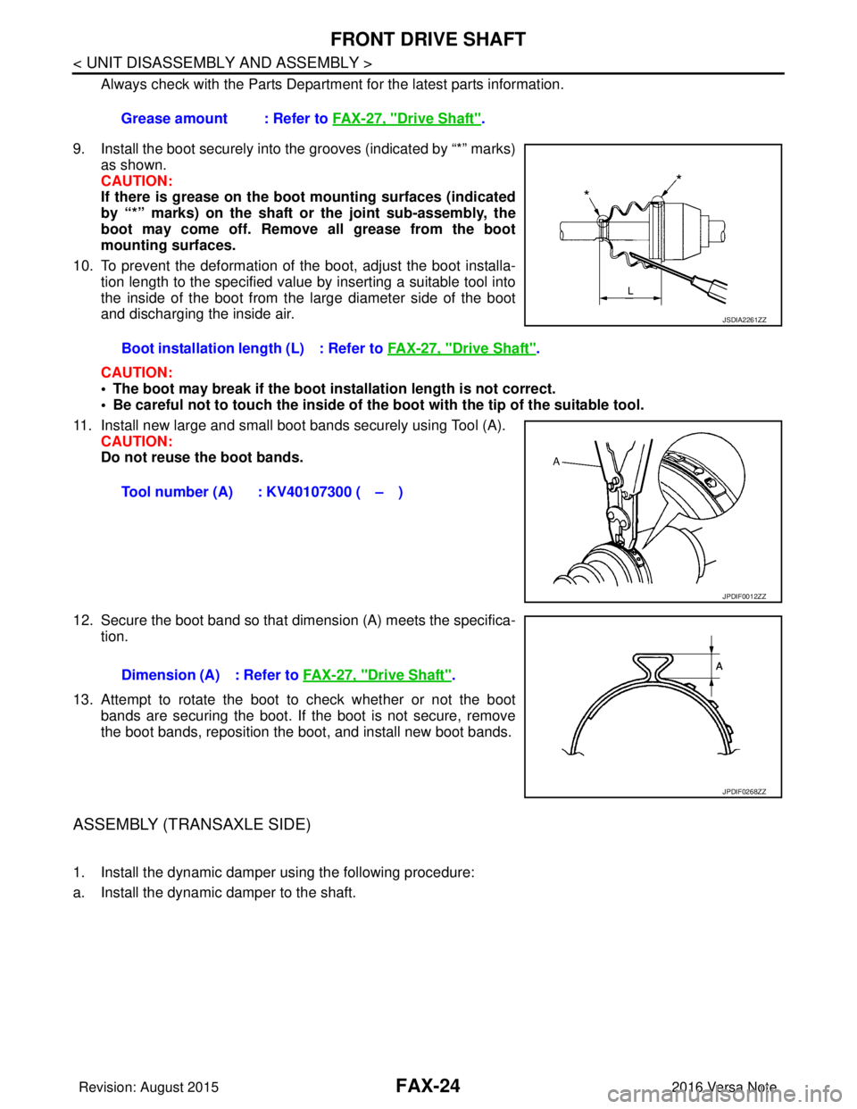
9. Install the boot securely into the grooves (indicated by “*” marks) as shown.
CAUTION:
If there is grease on the boot mounting surfaces (indicated
by “*” marks) on the shaft or the joint sub-assembly, the
boot may come off. Remove all grease from the boot
mounting surfaces.
10. To prevent the deformation of the boot, adjust the boot installa- tion length to the specified value by inserting a suitable tool into
the inside of the boot from the large diameter side of the boot
and discharging the inside air.
CAUTION:
• The boot may break if the boot installation length is not correct.
• Be careful not to touch the inside of the boot with the tip of the suitable tool.
11. Install new large and small boot bands securely using Tool (A). CAUTION:
Do not reuse the boot bands.
12. Secure the boot band so that dimension (A) meets the specifica- tion.
13. Attempt to rotate the boot to check whether or not the boot bands are securing the boot. If the boot is not secure, remove
the boot bands, reposition the boot, and install new boot bands.
ASSEMBLY (TRANSAXLE SIDE)
1. Install the dynamic damper using the following procedure:
a. Install the dynamic damper to the shaft. Grease amount : Refer to
FAX-27, "
Drive Shaft".
Boot installation length (L) : Refer to FAX-27, "
Drive Shaft".
Tool number (A) : KV40107300 ( – )
JSDIA2261ZZ
JPDIF0012ZZ
Dimension (A) : Refer to FAX-27, "Drive Shaft".
JPDIF0268ZZ
Revision: August 2015 2016 Versa Note
cardiagn.com