Page 1762 of 3641

EXL-110
< REMOVAL AND INSTALLATION >
REAR COMBINATION LAMP
2. Rotate stop/tail lamp bulb socket counterclockwise and remove.
3. Remove stop/tail lamp bulb from bulb socket.
Installation
Installation is in the reverse order of removal.
CAUTION:
After installing the bulb, install bulb socket securely for watertightness.
REAR TURN SIGNAL LAMP BULB
Removal
1. Remove rear combination lamp. Refer to EXL-109, "Removal and Installation".
2. Rotate rear turn signal lamp bulb socket counterclockwise and remove.
3. Remove rear turn signal lamp bulb from bulb socket.
Installation
Installation is in the reverse order of removal.
CAUTION:
After installing the bulb, install bu lb socket securely for watertightness.
BACK-UP LAMP BULB
Removal
1. Remove rear combination lamp. Refer to EXL-109, "Removal and Installation".
2. Rotate back-up lamp bulb socket counterclockwise and remove.
3. Remove back-up lamp bulb from bulb socket.
Installation
Installation is in the reverse order of removal.
CAUTION:
After installing the bulb, install bu lb socket securely for watertightness.
Revision: August 2015 2016 Versa Note
cardiagn.com
Page 1765 of 3641

FRONT COMBINATION LAMPEXL-113
< UNIT DISASSEMBLY AND ASSEMBLY >
C
DE
F
G H
I
J
K
M A
B
EXL
N
O P
UNIT DISASSEMBLY AND ASSEMBLY
FRONT COMBINATION LAMP
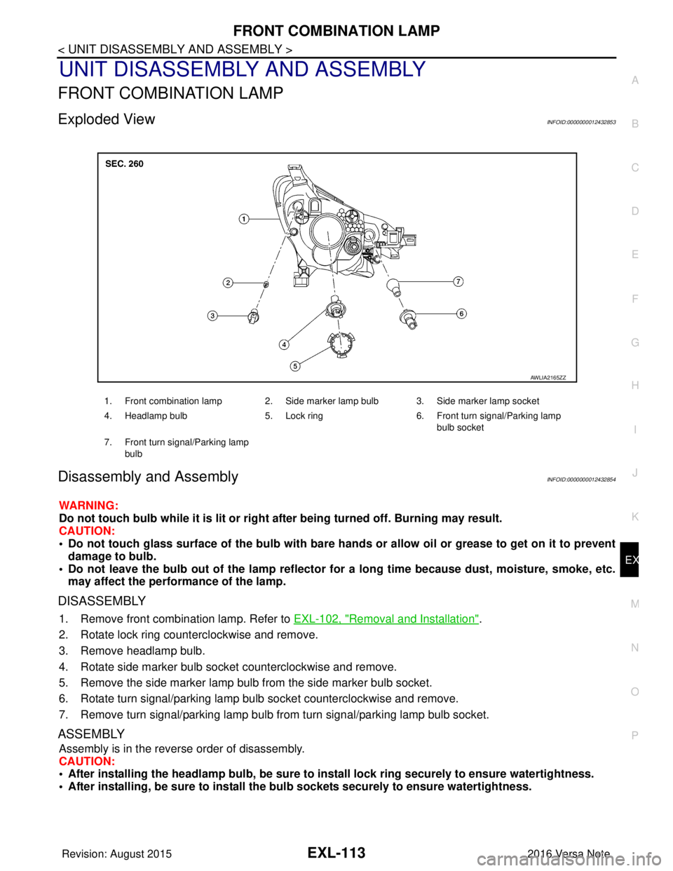
Exploded ViewINFOID:0000000012432853
Disassembly and AssemblyINFOID:0000000012432854
WARNING:
Do not touch bulb while it is lit or right after being turned off. Burning may result.
CAUTION:
• Do not touch glass surface of the bulb with bare hands or allow oil or grease to get on it to prevent damage to bulb.
• Do not leave the bulb out of the lamp reflector for a long time because dust , moisture, smoke, etc.
may affect the performance of the lamp.
DISASSEMBLY
1. Remove front combination lamp. Refer to EXL-102, "Removal and Installation".
2. Rotate lock ring counterclockwise and remove.
3. Remove headlamp bulb.
4. Rotate side marker bulb socket counterclockwise and remove.
5. Remove the side marker lamp bulb from the side marker bulb socket.
6. Rotate turn signal/parking lamp bulb socket counterclockwise and remove.
7. Remove turn signal/parking lamp bulb from turn signal/parking lamp bulb socket.
ASSEMBLY
Assembly is in the reverse order of disassembly.
CAUTION:
• After installing the headlamp bulb, be sure to install lock ring securely to ensure watertightness.
• After installing, be sure to install the bulb sockets securely to ensure watertightness.
1. Front combination lamp 2. Side marker lamp bulb 3. Side marker lamp socket
4. Headlamp bulb 5. Lock ring 6. Front turn signal/Parking lamp
bulb socket
7. Front turn signal/Parking lamp bulb
AWLIA2165ZZ
Revision: August 2015 2016 Versa Note
cardiagn.com
Page 1766 of 3641

EXL-114
< UNIT DISASSEMBLY AND ASSEMBLY >
REAR COMBINATION LAMP
REAR COMBINATION LAMP
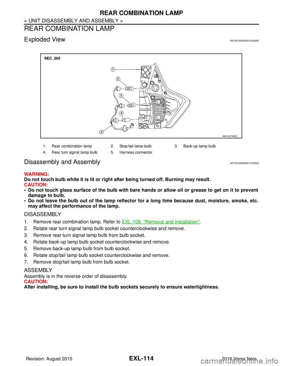
Exploded ViewINFOID:0000000012432855
Disassembly and Assembly INFOID:0000000012432856
WARNING:
Do not touch bulb while it is lit or right after being turned off. Burning may result.
CAUTION:
• Do not touch glass surface of the bulb with bare hands or allow oil or grease to get on it to preventdamage to bulb.
• Do not leave the bulb out of the lamp reflector fo r a long time because dust, moisture, smoke, etc.
may affect the performance of the lamp.
DISASSEMBLY
1. Remove rear combination lamp. Refer to EXL-109, "Removal and Installation".
2. Rotate rear turn signal lamp bulb socket counterclockwise and remove.
3. Remove rear turn signal lamp bulb from bulb socket.
4. Rotate back-up lamp bulb socket counterclockwise and remove.
5. Remove back-up lamp bulb from bulb socket.
6. Rotate stop/tail lamp bulb socket counterclockwise and remove.
7. Remove stop/tail lamp bulb from bulb socket.
ASSEMBLY
Assembly is in the reverse order of disassembly.
CAUTION:
After installing, be sure to install the bu lb sockets securely to ensure watertightness.
1. Rear combination lamp 2. Stop/tail lamp bulb 3. Back-up lamp bulb
4. Rear turn signal lamp bulb 5. Harness connector
AWLIA2166ZZ
Revision: August 2015 2016 Versa Note
cardiagn.com
Page 1767 of 3641
SERVICE DATA AND SPECIFICATIONS (SDS)EXL-115
< SERVICE DATA AND SPECIFICATIONS (SDS)
C
DE
F
G H
I
J
K
M A
B
EXL
N
O P
SERVICE DATA AND SPECIFICATIONS (SDS)
SERVICE DATA AND SPECIFICATIONS (SDS)
Bulb specificationINFOID:0000000012432857
*: Always check with the Parts Department for the latest parts info.
Item Wattage (W)*
Front combination Headlamp (HI/LO)
65/55
Front Turn signal/Parking lamp 28/8
Side marker lamp 5
Fog lamp (if equipped) 55
Door mirror turn signal lamp (if equipped) LED
Rear combination Stop/Tail lamp
21/5
Rear turn signal lamp 21
Back-up lamp 21
License plate lamp 5
High-mounted stop lamp LED
Revision: August 20152016 Versa Note
cardiagn.com
Page 2137 of 3641

INTERIOR ROOM LAMP CONTROL CIRCUITINL-43
< DTC/CIRCUIT DIAGNOSIS >
C
DE
F
G H
I
J
K
M A
B
INL
N
O P
INTERIOR ROOM LAMP CONTROL CIRCUIT
DescriptionINFOID:0000000012432742
Controls each interior room lamp (ground side) by PWM signal.
NOTE:
PWM signal control period is approximately 250 Hz (in the gradual brightening/dimming).
Component Function CheckINFOID:0000000012432743
CAUTION:
Before performing the diagnosis, check that the following are normal.
• Interior room lamp power supply
• Map lamp bulb
• Room lamp bulb
1.CHECK INTERIOR ROOM LAMP CONTROL FUNCTION
CONSULT
1. Switch the map lamp switch or interior room lamp switch to DOOR.
2. Turn ignition switch ON.
3. Select INT LAMP of BCM (INT LAMP) ACTIVE TEST item.
4. While operating the test items, check that each interior room lamp turns ON/OFF.
Does the interior room lamp turn s ON/OFF (gradual brightening/dimming)?
YES >> Interior room lamp control circuit is normal.
NO >> Refer to INL-43, "
Diagnosis Procedure".
Diagnosis ProcedureINFOID:0000000012432744
Regarding Wiring Diagram information, refer to INL-21, "Wiring Diagram".
1.CHECK INTERIOR ROOM LAMP CONTROL OUTPUT
CONSULT
1. Turn ignition switch OFF.
2. Remove all the bulbs of map lamp and interior room lamp.
3. Turn ignition switch ON.
4. Select INT LAMP of BCM (INT LAMP) ACTIVE TEST item.
5. While operating the test item, check c ontinuity between BCM harness connector and ground.
With Intelligent Key system
Without Intelligent Key system
Is the inspection result normal?
YES >> GO TO 2.
Fixed ON>>GO TO 3.On : Interior room lamp gradual brightening
Off : Interior room lamp gradual dimming
BCM
GroundTest item
Continuity
Connector Terminal
M99 63 INT LAMPOn
Yes
Off No
BCM GroundTest item
Continuity
Connector Terminal
M19 45 INT LAMPOn
Yes
Off No
Revision: August 2015 2016 Versa Note
cardiagn.com
Page 3308 of 3641
![NISSAN NOTE 2016 Service Repair Manual COMPONENT PARTSTM-67
< SYSTEM DESCRIPTION > [CVT: RE0F11A]
C
EF
G H
I
J
K L
M A
B
TM
N
O P
The O/D OFF indicator notifies the driver that the shift control of
transmaxle is in O/D OFF.
BULB CHECK
Appr NISSAN NOTE 2016 Service Repair Manual COMPONENT PARTSTM-67
< SYSTEM DESCRIPTION > [CVT: RE0F11A]
C
EF
G H
I
J
K L
M A
B
TM
N
O P
The O/D OFF indicator notifies the driver that the shift control of
transmaxle is in O/D OFF.
BULB CHECK
Appr](/manual-img/5/57363/w960_57363-3307.png)
COMPONENT PARTSTM-67
< SYSTEM DESCRIPTION > [CVT: RE0F11A]
C
EF
G H
I
J
K L
M A
B
TM
N
O P
The O/D OFF indicator notifies the driver that the shift control of
transmaxle is in O/D OFF.
BULB CHECK
Approximately 2 seconds after ignition switch ON.
OPERATION AT COMBNATION METER CNA COMMUNICATION CUT-OFF OR UNUSUAL SIGNAL
For actions on CAN communications blackout in the combnation meter, refer to MWI-23, "Fail-safe".
SYSTEM DIAGRAM
SIGNAL PATH
• When a overdrive control switch signal is input to the combination meter, the combination meter transmits
the overdrive control switch signal to the TCM via CAN communication.
• When all of the following conditions are satisfied, t he TCM transmits a O/D OFF indicator signal to the com-
bination meter via CAN communication. The combination meter turns ON the O/D OFF indicator lamp on the
combination meter, according to the signal.
- TCM receives overdrive control switch signal via CAN communication from combination meter.
- Selector lever: D position
LIGHTING CONDITION
When all of the following conditions are satisfied.
• Ignition switch: ON
• Selector lever: D position
• Overdrive control switch is pressed when the O/D OFF indicator lamp is OFF.
SHUTOFF CONDITION
When any of the conditions listed below is satisfied.
• Ignition switch: Other than ON
• Overdrive control switch is pressed when the O/D OFF indicator lamp is ON.
• Selector lever is shifted to other than D position when the O/D OFF indicator lamp is ON.
JPNIA1891ZZ
JSDIA3606GB
Revision: August 2015 2016 Versa Note
cardiagn.com
Page 3309 of 3641
![NISSAN NOTE 2016 Service Repair Manual TM-68
< SYSTEM DESCRIPTION >[CVT: RE0F11A]
COMPONENT PARTS
TIMING CHART
CVT CONTROL SYSTEM : Sh
ift Position IndicatorINFOID:0000000012431007
TCM transmits shift position signal to combination meter v NISSAN NOTE 2016 Service Repair Manual TM-68
< SYSTEM DESCRIPTION >[CVT: RE0F11A]
COMPONENT PARTS
TIMING CHART
CVT CONTROL SYSTEM : Sh
ift Position IndicatorINFOID:0000000012431007
TCM transmits shift position signal to combination meter v](/manual-img/5/57363/w960_57363-3308.png)
TM-68
< SYSTEM DESCRIPTION >[CVT: RE0F11A]
COMPONENT PARTS
TIMING CHART
CVT CONTROL SYSTEM : Sh
ift Position IndicatorINFOID:0000000012431007
TCM transmits shift position signal to combination meter via CAN communication. The actual shift position is
displayed on combination meter according to the signal.
CVT CONTROL SYSTEM : Malfunc tion Indicator Lamp (MIL)INFOID:0000000012431008
The malfunction indicator lamp (MIL) is located on the combination
meter.
The MIL will illuminate when the ignition switch is turned ON without
the engine running. This is a bulb check.
When the engine is started, the MIL should turn off. If the MIL
remains illuminated, the on board diagnostic system has detected an
engine system malfunction.
For details, refer to EC-57, "
DIAGNOSIS DESCRIPTION : Malfunc-
tion Indicator Lamp (MIL)".
SHIFT LOCK SYSTEM
SHIFT LOCK SYSTEM : Co mponent Parts LocationINFOID:0000000012431009
JSDIA3607GB
JSBIA1315ZZ
ALDIA0267ZZ
Revision: August 2015 2016 Versa Note
cardiagn.com