Page 173 of 465

WARNING
●Always be sure the liftgate has been
closed securely to prevent it from open-
ing while driving.
●Do not drive with the liftgate open. This
could allow dangerous exhaust gases
to be drawn into the vehicle. For addi-
tional information, refer to “Exhaust
gas (carbon monoxide)” in the “Starting
and driving” section of this manual.
●To help avoid risk of injury or death
through unintended operation of the
vehicle and or its systems, including
entrapment in windows or inadvertent
door lock activation, do not leave chil-
dren, people who require the assistance
of others or pets unattended in your
vehicle. Additionally, the temperature
inside a closed vehicle on a warm day
can quickly become high enough to
cause a significant risk of injury or
death to people and pets.
●Always be sure that hands and feet are
clear of the door frame to avoid injury
while closing the liftgate.
CAUTION
Do not use accessory carriers that attach
to the rear hatch. Doing so will cause dam-
age to the vehicle.
OPERATING THE MANUAL
LIFTGATE (if so equipped)
The power door lock system allows you to lock or
unlock all doors including the liftgate simultane-
ously.
To open the liftgate, press the liftgate opener
switch
�Aand pull up on the handle.
To close, lower and push the liftgate down se-
curely.
LPD2318
LIFTGATE
3-22Pre-driving checks and adjustments
Page 174 of 465

WARNING
●Make sure that all passengers have
their hands, etc., inside the vehicle be-
fore closing the liftgate.
●Do not leave children unattended ins")
OPERATING THE POWER LIFTGATE
(if so equipped)
WARNING
●Make sure that all passengers have
their hands, etc., inside the vehicle be-
fore closing the liftgate.
●Do not leave children unattended inside
the vehicle. They could unknowingly ac-
tivate switches or controls. Unattended
children could become involved in seri-
ous accidents.NOTE:
To open, close or reverse the power liftgate,
the shift lever must be in P (Park) . Also, the
power liftgate will not operate if battery
voltage is low.
Power Open:
The power liftgate automatically moves from the
fully closed position to the fully open position in
approximately5–8seconds. The power open
feature can be activated by the switch on the
Intelligent Key, the instrument panel switch and
the liftgate request switch. A chime sounds to
indicate the power open sequence has been
started.
●The liftgate can be opened by the instrument
panel switch, liftgate request switch and the
Intelligent Key even if the vehicle is locked.
The liftgate will individually unlock and open.
Once the liftgate is closed, the vehicle will
remain in the unlock status.
●The Intelligent Key button must be held for
1 second before the liftgate opens.
●The liftgate must be unlocked to open it with
the liftgate opener switch
�A.
A warning chime will sound if the shift lever is
moved out of P (Park) during a power open
operation.
Instrument panel switch
LPD2212
Liftgate opener switch
LPD2295
Pre-driving checks and adjustments3-23
Page 178 of 465

The liftgate release mechanism allows the liftgate
to be opened in the event of a discharged battery.
To release the liftgate from the inside of the
vehicle, perfor")
Liftgate release (manual and power)
The liftgate release mechanism allows the liftgate
to be opened in the event of a discharged battery.
To release the liftgate from the inside of the
vehicle, perform the following operations:
1. Position the rear bench seat forward. For
additional information, refer to “Rear bench
seat adjustment” in the “Safety—Seats, seat
belts and supplemental restraint system”
section of this manual.
2. Insert a suitable tool into the top access
opening at about a 45 degree angle and
rotate to the left until the lock releases.3. Push the liftgate up to open.
NOTE:
If you had to open the liftgate using this
procedure, have your vehicle checked as
soon as possible. It is recommended that
you visit a NISSAN dealer for this service.
LIFTGATE POSITION SETTING
The liftgate can be set to open to a specific height
by performing the following:
1. Open the liftgate using the request switch or
the Intelligent Key.
2. Pull the liftgate down to the desired position
and hold the liftgate (the liftgate will have
some resistance when being manually ad-
justed) .
3. While holding the liftgate in position, push
and hold the liftgate switch
located
on the liftgate for approximately 5 seconds
or until two beeps are heard.
The liftgate will open to the selected position
setting. To change the position of the liftgate,
repeat Steps 1-3 for setting the position of the
liftgate.
OPENER OPERATION
The fuel-filler door release is located below the
instrument panel. To open the fuel-filler door, pull
the release. To lock, close the fuel-filler door
securely.
LPD2319LPD2022
FUEL-FILLER DOOR
Pre-driving checks and adjustments3-27
Page 180 of 465
NOTE:
Changing ignition switch status during the
refueling process may cause a delay in fuel
gauge response.
To remove the fuel-filler cap:
1. Turn the fuel-filler cap counterclockwise to
remove.
2. Put the fuel-filler cap on the cap holder
�1
while refueling.
To install the fuel-filler cap:
1. Insert the fuel-filler cap straight into the fuel-
filler tube.
2. Turn the fuel-filler cap clockwise until a
single click is heard.
LOOSE FUEL CAP warning
The LOOSE FUEL CAP warning message ap-
pears in the vehicle information display when the
fuel-filler cap is not tightened correctly after the
vehicle has been refueled. It may take a few
driving trips for the message to be displayed. To
turn off the warning message, perform the follow-
ing:
1. Remove and install the fuel-filler cap as soon
as possible. For additional information, refer
to “Fuel-filler cap” in this section.
2. Tighten the fuel-filler cap until it clicks.
LPD2288LPD2298
Pre-driving checks and adjustments3-29
Page 181 of 465

3. Press thebutton on the steering
wheel for about one second to turn off the
LOOSE FUEL CAP warning message after
tightening the fuel-filler cap.WARNING
●Do not adjust the steering wheel while
driving. You could lose control of your
vehicle and cause an accident.
●Do not adjust the steering wheel any
closer to you than is necessary for
proper steering operation and comfort.
The driver’s air bag inflates with great
force. If you are unrestrained, leaning
forward, sitting sideways or out of posi-
tion in any way, you are at greater risk of
injury or death in a crash. You may also
receive serious or fatal injuries from the
air bag if you are up against it when it
inflates. Always sit back against the
seatback and as far away as practical
from the steering wheel. Always use the
seat belts.
MANUAL OPERATION (if so
equipped)
Tilt and telescopic operation
Pull the lock lever�1down:
●Adjust the steering wheel up or down in
direction
�2to the desired position.
●Adjust the steering wheel forward or back-
ward in direction
�3to the desired position.
Push the lock lever
�1up firmly to lock the
steering wheel in place.
LPD2339
STEERING WHEEL
3-30Pre-driving checks and adjustments
Page 182 of 465

Tilt and telescopic operation
To adjust the steering wheel move the switch�1
in the following directions:
●Adjust the steering wheel up or down in
direction
�2to")
AUTOMATIC OPERATION (if so
equipped)
Tilt and telescopic operation
To adjust the steering wheel move the switch�1
in the following directions:
●Adjust the steering wheel up or down in
direction
�2to the desired tilt position.
●Adjust the steering wheel forward or back-
ward in direction
�3to the desired tele-
scopic position.
CAUTION
For vehicles with automatic drive posi-
tioner: Failure to reset the tilt and tele-
scoping functions of the steering wheel,
after the vehicle’s battery has been dis-
charged, may prevent the steering wheel
position from being adjusted.
For vehicles with automatic drive positioner: Both
the tilt and telescopic steering operation must be
reset after the vehicle’s battery has been dis-
charged in order to prevent the tilt and telescopic
operation from locking in one position. When the
battery has been recharged or replaced, perform
the following:
●For tilt operation: Adjust the switch
�1so
the steering wheel moves to the highest
position
�2that can be reached.
●For telescopic operation: Adjust the switch
�1so the steering wheel moves to the most
forward and backward position
�3that can
be reached.
Performing these operations resets the range of
the steering wheel’s tilt and telescopic function.
Entry/Exit function
The automatic drive positioner system will make
the steering wheel move up automatically when
the driver’s door is opened and the ignition
switch is in the LOCK position. This lets the driver
get into and out of the seat more easily. The
steering wheel moves back into position when
the driver’s door is closed and the ignition switch
is pushed.
For additional information, refer to “Automatic
drive positioner” in this section.
LPD2410
Pre-driving checks and adjustments3-31
Page 183 of 465
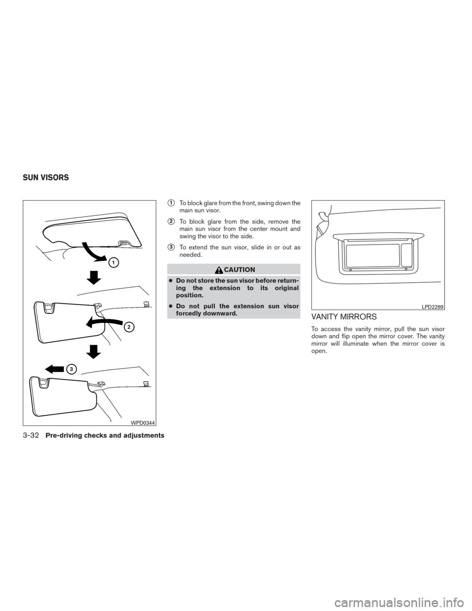
�1To block glare from the front, swing down the
main sun visor.
�2To block glare from the side, remove the
main sun visor from the center mount and
swing the visor to the side.
�3To extend the sun visor, slide in or out as
needed.
CAUTION
●Do not store the sun visor before return-
ing the extension to its original
position.
●Do not pull the extension sun visor
forcedly downward.
VANITY MIRRORS
To access the vanity mirror, pull the sun visor
down and flip open the mirror cover. The vanity
mirror will illuminate when the mirror cover is
open.
WPD0344
LPD2289
SUN VISORS
3-32Pre-driving checks and adjustments
Page 187 of 465

Use the following process to setup key-link:
1. Unlock the vehicle with the desired Intelli-
gent Key while the ignition is OFF.
2. Place the ignition in the ON posi")
MEMORY STORAGE FUNCTION
(Key-Link)
Use the following process to setup key-link:
1. Unlock the vehicle with the desired Intelli-
gent Key while the ignition is OFF.
2. Place the ignition in the ON position.
3. Within the “Settings” menu of the vehicle
information display, select “Key-Linked Set-
tings” and press the OK button on the steer-
ing switch.4. While in the menu, press the OK button on
the steering switch to turn the system
ON/OFF.
Once step 4 is completed, every time the ignition
is switched from ON to OFF, the memory posi-
tions of the driver’s seat, automatic steering
wheel (if so equipped) and the outside mirrors
are linked to the Intelligent Key.
Follow the same procedure if you want to
link the 2nd, 3rd or 4th Intelligent Key.
NOTE:
If new memory positions are set prior to
turning the ignition from ON to OFF, the
previously linked memory positions for the
respective key will be overwritten by new
positions.
Recalling Intelligent Key Memory
Positions
If the “Key-Linked Settings” are enabled in the
vehicle information display for that particular key,
every time you enter the vehicle the driver’s seat,
automatic steering wheel (if so equipped) , and
outside mirrors will automatically move to the
driver’s last position of the respective Intelligent
Key.NOTE:
The key-linked memory positions can be
different from the positions stored in the
memory switch (1 or 2) .
LPD2432
3-36Pre-driving checks and adjustments