2016 NISSAN MURANO HYBRID battery
[x] Cancel search: batteryPage 34 of 49
4. Jump Starting
T
o start the hybrid system with a booster battery, the instructions and precautions below must be followed. If done incorrectly, jump starting can lead to a 12-volt battery explosion, resulting in severe
personal
injury or death. It could also damage your vehicle.
Jump starting provides power to the 12-volt system to allow the electrical systems to operate. The electrical
systems must be operating to allow the high-voltage battery to be charged. Jump starting does not charge
the high-voltage battery.
Discharged 12-volt battery may cause the following issues: • The instrument cluster cannot be displayed while the ignition switch is turned ON. (The hybridsystem cannot start.)
• Headlamps, horn, etc. are weak. • To avoid electrical shock, the high-voltage battery CANNOT be jump started.
•
Explosive hydrogen gas is always present in the vicinity of the 12-volt battery. Keep all
sparks and flames away from the 12-volt battery. Make sure the vent tube is mounted.
• Do not allow battery fluid to come into contact with eyes, skin, clothing or painted surfaces. Battery fluid is a corrosive sulfuric acid solution that can cause severe burns.
If the fluid comes into contact with anything, immediately flush the contacted area
with water.
• The booster battery must be rated at 12 volts. Use of an improperly rated battery can damage the vehicle.
• Whenever working on or near a 12-volt battery, always wear suitable eye protectors (for example, goggles or industrial safety spectacles) and remove rings, metal bands, or any
other jewelry. Do not lean over the 12-volt battery when jump starting.
• Do not attempt to jump start a frozen battery. It could explode and cause serious injury.
• Murano HYBRID is equipped with an automatic cooling fan. It could come on at any time. Keep hands and other objects away from it.
• Always follow the jump starting instructions below. Failure to do so could result in damage to the charging system and cause personal injury.
DG–34
Page 35 of 49
4-1 Jump Starting Procedures
NO
TE:
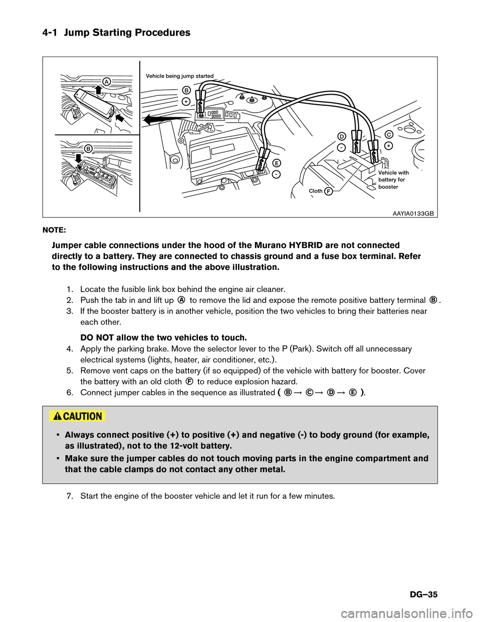
Jumper cable connections under the hood of the Murano HYBRID are not connected
directly to a battery. They are connected to chassis ground and a fuse box terminal. Refer
to the following instructions and the above illustration.
1. Locate the fusible link box behind the engine air cleaner.
2. Push the tab in and lift up ○A
to remove the lid and expose the remote positive battery terminal
○B
.
3. If the booster battery is in another vehicle, position the two vehicles to bring their batteries near each other.
DO NOT allow the two vehicles to touch.
4. Apply the parking brake. Move the selector lever to the P (Park) . Switch off all unnecessary electrical systems (lights, heater, air conditioner, etc.) .
5. Remove vent caps on the battery (if so equipped) of the vehicle with battery for booster. Cover the battery with an old cloth ○F
to reduce explosion hazard.
6. Connect jumper cables in the sequence as illustrated (
○B
�
○C
�
○D
�
○E
). • Always connect positive (+) to positive (+) and negative (-) to body ground (for example,
as
illustrated) , not to the 12-volt battery.
• Make sure the jumper cables do not touch moving parts in the engine compartment and that the cable clamps do not contact any other metal.
7. Start the engine of the booster vehicle and let it run for a few minutes. A
B
+
E
F
-
D
-
C
+
B
Cloth
Vehicle being jump started
Vehicle with
battery for
boosterAAYIA0133GB
DG–35
Page 36 of 49
8. Hold down the brake pedal and press the START button. The vehicle instruments and gauges will
light up, and the green READY light will come ON.
If the green READY light does not come on, press the START button to turn the
Hybrid
System OFF. Carefully disconnect the negative cable then the positive cable. It is
recommended you visit a NISSAN dealer for repair.
9. After the green READY light in the meter display comes ON, carefully disconnect the
negative
cable and then the positive cable.
10. Replace the vent caps (if so equipped) . Be sure to dispose of the cloth used to cover the vent holes as it may be contaminated with corrosive acid.
11. Reinstall the fusible link box cover.
NOTE:
If it is not possible to turn the hybrid system ON by following this procedure, it is
recommended you contact a NISSAN dealer immediately.
4-2 Shift Selector Lever Lock Release
If the 12-volt battery is low or discharged, the selector lever cannot be moved from the Park (P) position. If a
booster battery is not available, the selector lever lock can be manually released. To manually release the
selector lever lock, perform the following procedure: 1. Push the ignition switch to the LOCK or OFF position.
2. Apply the parking brake.
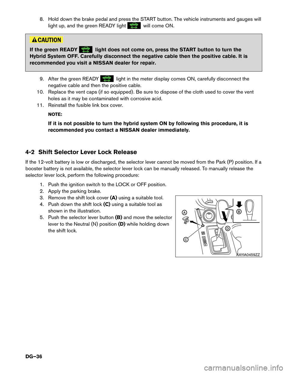
3. Remove the shift lock cover (A)using a suitable tool.
4. Push down the shift lock (C)using a suitable tool as
shown in the illustration.
5. Push the selector lever button (B)and move the selector
lever to the Neutral (N) position (D)while holding down
the shift lock. C B
D
A
AAYIA0459ZZ
DG–36
Page 37 of 49
5. Storing the Vehicle
The service plug must be removed to shut down the high-voltage system for storage.
Do
not store a vehicle inside a structure. Keep the vehicle away from other vehicles if the
high-voltage battery is severely damaged. There is possibility of delayed fire from a severely
damaged high-voltage battery.
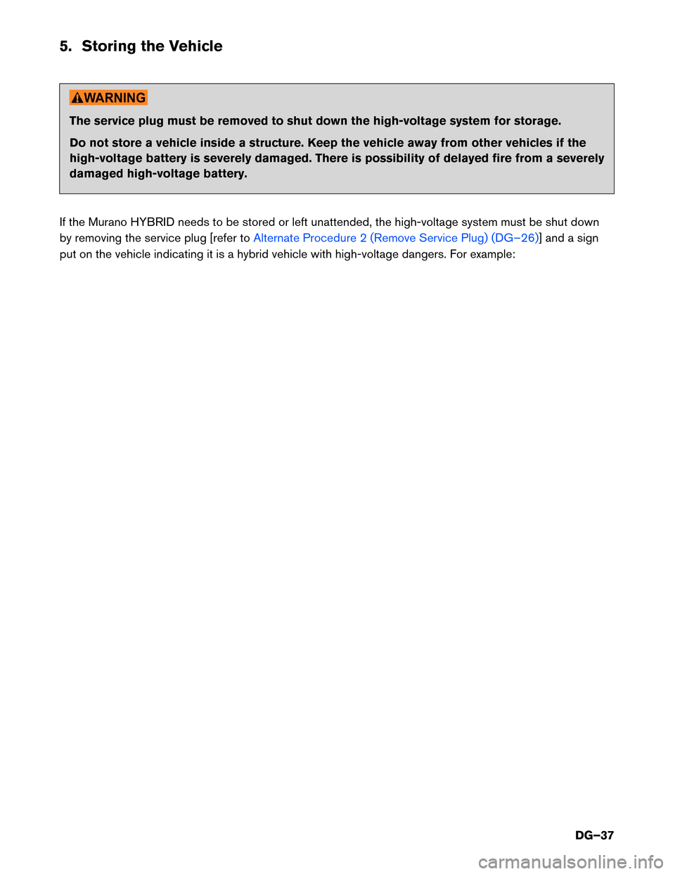
If the Murano HYBRID needs to be stored or left unattended, the high-voltage system must be shut down
by removing the service plug [refer to Alternate Procedure 2 (Remove Service Plug) (DG–26)] and a sign
put
on the vehicle indicating it is a hybrid vehicle with high-voltage dangers. For example:
DG–37
Page 39 of 49
6. Dismantling Information
Removal
or repair of the high-voltage battery requires special tools and specific training. Nissan strongly
recommends that only certified NISSAN dealer technicians perform these operations.
6-1 Precautions for Handling High-voltage Battery DANGER
• Because Murano HYBRID contains a high-voltage battery, there is the risk of
electric
shock, electric leakage, or similar accidents if the high-voltage components or
vehicle is handled incorrectly. Be sure to follow the correct work procedures when
performing inspection and dismantling.
• If it is necessary to touch any of the high-voltage harnesses or components you
must
always wear appropriate Personal Protective Equipment (PPE) and properly
shut-down the high-voltage system by removing the service plug.
•
Be sure to always wear appropriate PPE before beginning work on the high-voltage
system.
•Be sure to remove the service plug in order to shut-down the high-voltage system
before performing inspection or dismantling of high-voltage system harnesses and parts.
• If the vehicle is heavily damaged, for example the high-voltage battery is
deformed, broken, or cracked; appropriate PPE must always be used at all times to
avoid electrical shock. • The colors of the high-voltage harnesses and connectors are all orange. Orange
�high-voltage� labels
are applied to the high-voltage battery and other high-voltage
devices. Do not touch the high-voltage battery or other high-voltage devices without
always wearing appropriate PPE.
•
Clearly identify the persons responsible for high-voltage work and ensure that other
persons do not touch the vehicle. When not working, cover high-voltage parts with an
insulating cover sheet and sign or similar item to prevent other persons from contacting them.
• Be sure to put the removed service plug in your pocket and carry it with you so
another person does not accidentally reinstall it while work is in progress.
•
The high-voltage battery retains high-voltage at all times. Appropriate Personal Protective
Equipment (PPE) must always be worn when touching or working on high-voltage components
to avoid risk of electrical shock and severe personal injury or death.
• Immediately insulate disconnected high-voltage connectors and terminals with
insulated tape.
• The vehicle contains parts that contain powerful magnets. If a person who is wearing
a
pacemaker or other medical device is close to these parts, the medical device may be
affected by the magnets. Such persons must not perform work on the vehicle.
•
Because this vehicle uses components that contain high-voltage and powerful
magnetism, do not carry any metal products which may cause short circuits, or any magnetic
media (cash cards, credit cards, etc.) which may be damaged when working on the vehicle.
• Keep removed high-voltage battery packs away from rain to avoid electric shock.
•
Do not heat removed battery packs higher than 158° F (70° C) .
DG–39
Page 40 of 49
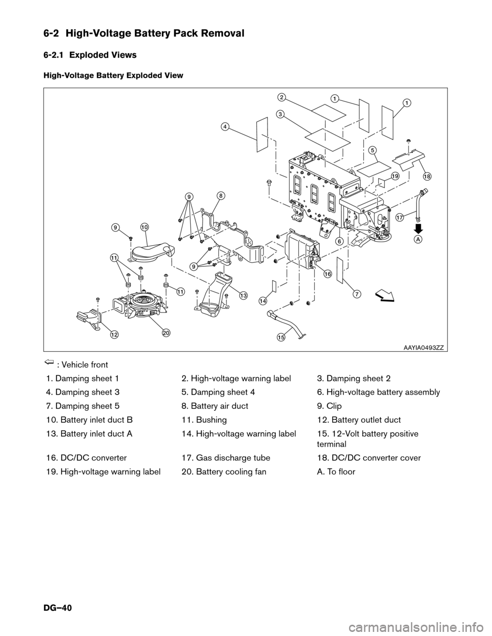
6-2 High-Voltage Battery Pack Removal
6-2.1
Exploded Views
High-Voltage Battery Exploded View : Vehicle front
1.
Damping sheet 1 2. High-voltage warning label 3. Damping sheet 2
4. Damping sheet 3 5. Damping sheet 4 6. High-voltage battery assembly
7. Damping sheet 5 8. Battery air duct9. Clip
10. Battery inlet duct B 11. Bushing12. Battery outlet duct
13. Battery inlet duct A 14. High-voltage warning label 15. 12-Volt battery positive
terminal
16. DC/DC converter 17. Gas discharge tube18. DC/DC converter cover
19. High-voltage warning label 20. Battery cooling fan A. To floor A1
5 12
3
4
8
9
20 11
13 16
76 1819
14
1511
12 10 9
9 17
AAYIA0493ZZ
DG–40
Page 42 of 49
6-2.2 Removal Procedure
1. Discharge high-voltage battery. Refer to 3-3 Discharge Procedures (DG–19).
2.
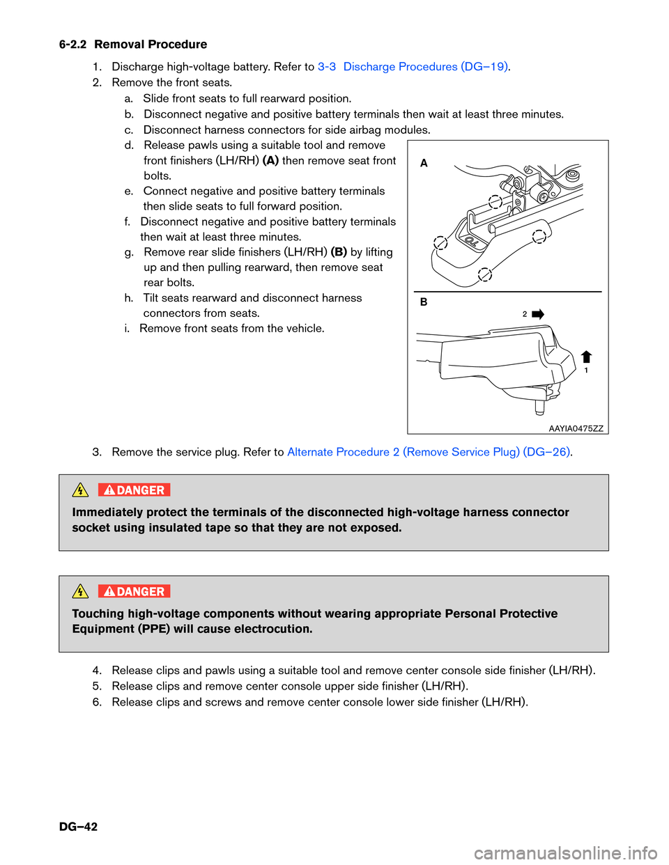
Remove the front seats. a. Slide front seats to full rearward position.
b. Disconnect negative and positive battery terminals then wait at least three minutes.
c. Disconnect harness connectors for side airbag modules.
d. Release pawls using a suitable tool and remove front finishers (LH/RH) (A)then remove seat front
bolts.
e. Connect negative and positive battery terminals then slide seats to full forward position.
f. Disconnect negative and positive battery terminals then wait at least three minutes.
g. Remove rear slide finishers (LH/RH) (B)by lifting
up and then pulling rearward, then remove seat
rear bolts.
h. Tilt seats rearward and disconnect harness connectors from seats.
i. Remove front seats from the vehicle.
3. Remove the service plug. Refer to Alternate Procedure 2 (Remove Service Plug) (DG–26).DANGER
Immediately protect the terminals of the disconnected high-voltage harness connector
socket
using insulated tape so that they are not exposed. DANGER
Touching high-voltage components without wearing appropriate Personal Protective
Equipment
(PPE) will cause electrocution.
4. Release clips and pawls using a suitable tool and remove center console side finisher (LH/RH) .
5. Release clips and remove center console upper side finisher (LH/RH) .
6. Release clips and screws and remove center console lower side finisher (LH/RH) . A
B 1
2 AAYIA0475ZZ
DG–42
Page 45 of 49
20. Disconnect the remaining harness connectors and remove center console.
21.
Remove the high-voltage battery.
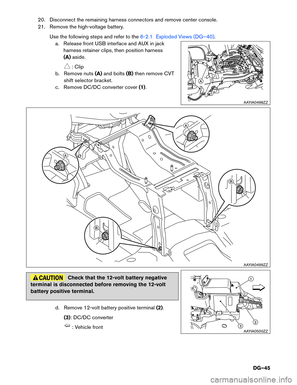
Use the following steps and refer to the 6-2.1 Exploded Views (DG–40).
a.
Release front USB interface and AUX in jack
harness retainer clips, then position harness
(A) aside. : Clip
b.
Remove nuts (A)and bolts (B)then remove CVT
shift selector bracket.
c. Remove DC/DC converter cover (1).Check that the 12-volt battery negative
terminal
is disconnected before removing the 12-volt
battery positive terminal.
d. Remove 12-volt battery positive terminal (2).
(3): DC/DC converter : Vehicle front A
AAYIA0498ZZ
A
B A
B
AAYIA0499ZZ
1
2
3
AAYIA0500ZZ
DG–45