Page 4 of 401

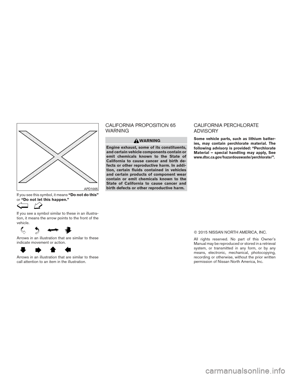
If you see this symbol, it means“Do not do this”
or “Do not let this happen.”
If you see a symbol similar to these in an illustra-
tion, it means the arrow points to the front of the
vehicle.
Arrows in an illustration that are similar to these
indicate movement or action.
Arrows in an illustration that are similar to these
call attention to an item in the illustration.
CALIFORNIA PROPOSITION 65
WARNING
WARNING
Engine exhaust, some of its constituents,
and certain vehicle components contain or
emit chemicals known to the State of
California to cause cancer and birth de-
fects or other reproductive harm. In addi-
tion, certain fluids contained in vehicles
and certain products of component wear
contain or emit chemicals known to the
State of California to cause cancer and
birth defects or other reproductive harm.
CALIFORNIA PERCHLORATE
ADVISORY
Some vehicle parts, such as lithium batter-
ies, may contain perchlorate material. The
following advisory is provided: “Perchlorate
Material – special handling may apply, See
www.dtsc.ca.gov/hazardouswaste/perchlorate/”.
© 2015 NISSAN NORTH AMERICA, INC.
All rights reserved. No part of this Owner’s
Manual may be reproduced or stored in a retrieval
system, or transmitted in any form, or by any
means, electronic, mechanical, photocopying,
recording or otherwise, without the prior written
permission of Nissan North America, Inc.
APD1005
Page 8 of 401
0 Illustrated table of contents
Air bags, seat belts and child restraints..............0-2
Exterior front ......................................0-3
Exterior rear .......................................0-4
Passenger compartment ...........................0-5 Instrument Panel
..................................0-6
Engine compartment check locations . . ..............0-8
Warning and indicator lights ........................0-9
Page 10 of 401
1. Engine hood (P. 3-20)
2. Wiper and washer switch (P. 2-36)
3. Windshield (P. 8-20)
4. Power windows (P. 2-51)
5. Door locks, NISSAN Intelligent Key®,keys (P. 3-3, 3-6, 3-2)
6. Mirrors, side view camera
(if so equipped) (P. 3-28, 4-9)
7. Tire pressure (P. 8-31)
8. Flat tire (P. 6-3)
9. Tire chains (P. 8-31)
10. Headlight and turn signal switch,
replacing bulbs (P. 2-38, 8-27)
11. Fog light switch (P. 2-38)
12. Sonar sensors (if so equipped)
(P. 5-84)
13. Front view camera (if so equipped)
(P. 4-9)
Refer to the page number indicated in pa-
rentheses for operating details.
LII2287
EXTERIOR FRONT
Illustrated table of contents0-3
Page 15 of 401
VQ35DE engine
1. Engine coolant reservoir (P. 8-8)
2. Drive belt location (P. 8-18)
3. Engine oil filler cap (P. 8-10)
4. Brake fluid reservoir (P. 8-14)
5. Air cleaner (P. 8-20)
6. Fuse block (P. 8-22)
7. Fuse block/Fusible links (P. 8-22)
8. Fusible links (P. 8-22)
9. Battery (P. 8-16)
10. Engine oil dipstick (P.8-10)
11. Radiator cap (P. 8-8)
12. Power steering fluid reservoir (P. 8-14)
13. Windshield-washer fluid reservoir(P. 8-15)
Refer to the page number indicated in pa-
rentheses for operating details.
LDI2749
ENGINE COMPARTMENT CHECK
LOCATIONS
0-8Illustrated table of contents
Page 16 of 401
Warninglight Name Page
Anti-lock Braking
System (ABS) warn-
ing light 2-7
or
Brake warning light 2-8
Charge warning
light
2-8
Engine oil pressure
warning light2-8
Forward emergency
braking system
warning light (if so
equipped)2-9
Low tire pressure
warning light
2-9
Warning
light Name Page
Master warning light 2-10
Power steering
warning light 2-11
Seat belt warning
light and chime2-11
Supplemental air
bag warning light2-11
Indicator
light Name Page
Front fog light indi-
cator light 2-12
Front passenger air
bag status light2-12
High beam indicator
light (blue)2-12
Indicator
light Name Page
Malfunction Indica-
tor Light (MIL) 2-12
Security indicator
light2-13
Side light and head-
light indicator light
(green)2-13
Slip indicator light 2-13
Turn signal/hazard
indicator lights
2-13
Vehicle Dynamic
Control (VDC) OFF
indicator light2-14
WARNING AND INDICATOR LIGHTS
Illustrated table of contents0-9
Page 20 of 401

FRONT POWER SEAT ADJUSTMENT
Operating tips
●The power seat motor has an auto-reset
overload protection circuit. If the motor
stops during operation, wait 30 seconds
then reactivate the switch.
● Do not operate the power seat switch for a
long period of time when the engine is off.
This will discharge the battery.
For additional information, refer to “Automatic
drive positioner” in the “Pre-driving checks and
adjustments” section of this manual.
Forward and backward
Moving the switch forward or backward will slide
the seat forward or backward to the desired
position.
Reclining
Move the recline switch backward until the de-
sired angle is obtained. To bring the seatback
forward again, move the switch forward and
move your body forward. The seatback will move
forward. The reclining feature allows adjustment of the
seatback for occupants of different sizes for
added comfort and to help obtain proper seat
belt fit. For additional information, refer to “Pre-
cautions on seat belt usage” in this section. Also,
the seatback can be reclined to allow occupants
to rest when the vehicle is stopped and the shift
lever is in P (Park) .
LRS2692
Safety—Seats, seat belts and supplemental restraint system1-3
Page 77 of 401

2 Instruments and controls
Instrument Panel..................................2-2
Meters and gauges ................................2-3
Speedometer and odometer .....................2-4
Tachometer ....................................2-5
Engine coolant temperature gauge ...............2-5
Fuel gauge ....................................2-6
Warning lights, indicator lights and audible
reminders .........................................2-7
Checking LED .................................2-7
Warning lights .................................2-7
Indicator lights ................................ 2-12
Audible reminders ............................. 2-14
Vehicle information display ......................... 2-15
How to use the vehicle information display .......2-15
Startup display ................................ 2-16
Drive computer ................................ 2-16
Settings ...................................... 2-17
Vehicle information display warnings and
indicators ..................................... 2-23
Control Panel and vehicle information display
Interaction ....................................... 2-27
Audio ........................................ 2-27
Receiving a call ............................... 2-28
Text Messaging ............................... 2-29Navigation System
............................. 2-31
Navigation Swipe to Meter ......................2-33
Security systems ................................. 2-34
Vehicle security system ......................... 2-34
NISSAN vehicle immobilizer system .............2-35
Wiper and washer switch ......................... 2-36
Switch operation .............................. 2-36
Rain-sensing auto wiper system
(if so equipped) ............................... 2-37
Rear window and outside mirror (if so equipped)
defroster switch .................................. 2-38
Headlight and turn signal switch ....................2-38
Headlight control switch ........................ 2-38
Daytime running light system ....................2-40
Instrument brightness control ...................2-41
Turn signal switch ............................. 2-41
Fog light switch ............................... 2-42
Horn ............................................ 2-42
Heated
seats (if so equipped) ...................... 2-43
Climate control seat switch (if so equipped) .........2-44
Heated steering wheel (if so equipped) .............2-45
Vehicle Dynamic Control (VDC) off switch ...........2-45
Power outlet ..................................... 2-46
Page 80 of 401
19. Cruise control main/Intelligent CruiseControl (ICC) (if so equipped) set
switches (P. 5-40, 5-42)
20. Hood release (P. 3-20)
21. Fuse box (P. 8-22)
22. Heated steering wheel switch
(if so equipped) (P. 2-45)
Vehicle Dynamic Control (VDC) OFF
switch (P. 2-45)
Trunk release switch (P. 3-21)
Rear power sunshade switch
(if so equipped) (P. 2-57)
23. Instrument brightness control
(P. 2-38)/Twin trip odometer reset
switch (P. 2-3)
* Refer to the separate Navigation System Own-
er’s Manual.
Refer to the page number indicated in pa-
rentheses for operating details.
1. Tachometer
2. Warning lights and indicator lights
3. Vehicle information display/Odometer/Twin trip odometer
4. Speedometer 5. Fuel gauge
6. Engine coolant temperature gauge
LIC3191
METERS AND GAUGES
Instruments and controls2-3