Page 17 of 46
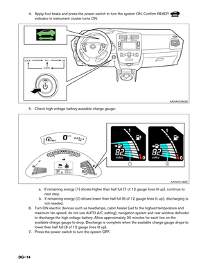
.
• The vehicle contains parts that contain powerful magnets. If a person wh")
• If the charge connector is connected to the vehicle, remove it. Refer to
3-4.1 Removing the Charge Connector (DG–18).
• The vehicle contains parts that contain powerful magnets. If a person who is
wearing a pacemaker or other medical device is close to these parts, the medical
device may be affected by the magnets. Such persons must not perform work on the
vehicle.
• Be sure to verify that the READY indicator is off and the high voltage system is
stopped.
•
After the high voltage system is shut down, please wait at least ten (10) minutes for
complete discharge of the high voltage capacitor. While waiting, do not operate any
vehicle functions.
• After shutting down the high voltage system and removing the 12-volt battery negative (-) terminal, wait at least three (3) minutes to discharge the air bag capacitor. Even
though the 12-volt battery negative (-) is disconnected, the Supplemental
Restraint System (SRS) air bag maintains voltage at least three (3) minutes. During
this time, there is a possibility of sudden SRS air bag inflation due to harness
short circuit or damage and it may cause serious injuries.
• Always shut down the high voltage system before disconnecting the 12-volt battery. Not doing so may result in serious injury or death from electrical shock.
• The 12V system will remain active even after the 12-volt battery negative (-) terminal is removed while the high voltage system is active. The high voltage system is active
during any of the following conditions:
• charging indicator is turned ON
• READY indicator is turned ON
Refer to 1-1.2 Interior Component Location (DG–7)
for location of these indicators.
This
is because DC/DC converter will not shut down and power will be supplied
to the 12V system and high voltage system continuously.
DG–17
Page 18 of 46
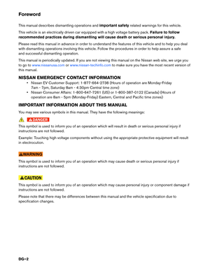
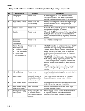
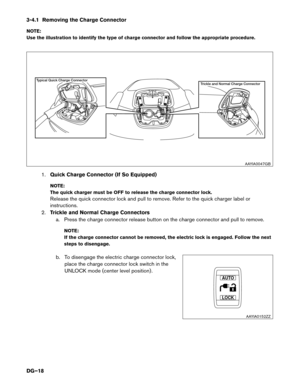
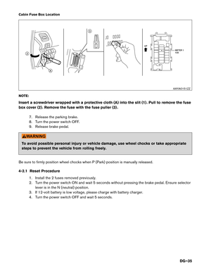
3-4.1 Removing the Charge Connector
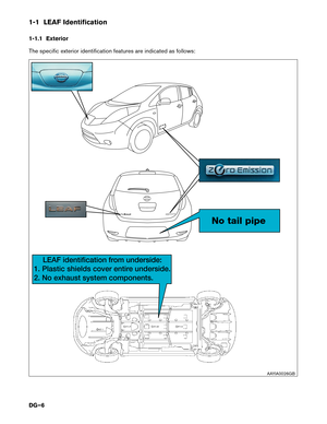
NO
TE:
Use the illustration to identify the type of charge connector and follow the appropriate procedure.
1.Quick Charge Connector (If So Equipped)
NOTE:
The quick charger must be OFF to release the charge connector lock.
Release the quick connector lock and pull to remove. Refer to the quick charger label or
instructions.
2. Trickle and Normal Charge Connectors
a. Press the charge connector release button on the charge connector and pull to remove.
NOTE:
If the charge connector cannot be removed, the electric lock is engaged. Follow the next
steps to disengage.
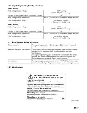
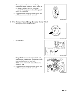
b. To disengage the electric charge connector lock, place the charge connector lock switch in the
UNLOCK mode (center level position) . Trickle and Normal Charge Connector
T
ypical Quick Charge Connector
AAYIA0047GB
LOCKAUTO AAYIA0152ZZ
DG–18
Page 19 of 46
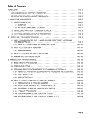
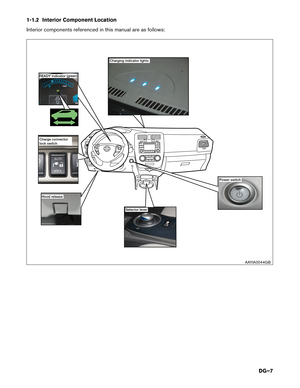
c. The charge connector can be unlocked by
pushing the charge connector unlock button on
the Nissan Intelligent Key® for more than
1 second. The charge connector will temporarily
unlock for 30 seconds.
d. Press the charge connector release button and pull the charge connector to remove it.
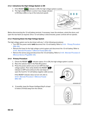
3. If the Trickle or Normal Charge Connector Cannot Unlock
a. Place power switch in OFF position.
b. Open the hood.
c. Using a flat head screwdriver (or suitable tool) , insert into the screw located through the access
hole near the front of the hood lock.
d. Rotate screw clockwise to release the charge connector lock.
e. Press the charge connector release button and pull the charge connector to remove it. HOLD
NISSAN
AAYIA0153ZZ
AAYIA0091ZZ
AAYIA0145ZZ
AAYIA0353ZZ
DG–19
Page 20 of 46

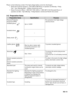
3-4.2 Indications the High Voltage System is ON
1. If the READY indicator is ON, the high voltage system is active.
2.
The high voltage system is active if any charge indicator
is ON (blue LEDs on top of the instrument panel) .
Before disconnecting the 12-volt battery terminal, if necessary, lower the windows, unlock the doors, and
open the rear hatch as required. Once 12-volt battery is disconnected, power controls will not operate.
3-4.3 Powering Down the High Voltage System
The high voltage system can be shut down with any 1 of the following procedures: • Turn OFF the power switch anddisconnect the 12-volt battery. Refer to
3-4.4 Primary Procedure
(DG–20) .
•
Remove the fuses for the high voltage control system and disconnect the 12-volt battery. Refer to
3-4.5 Alternate Procedure 1 (Remove Fuses) (DG–22).
•
Remove the service plug and disconnect the 12-volt battery. Refer to 3-4.6 Alternate Procedure 2
(Remove
Service Plug) (DG–24) .
3-4.4
Primary Procedure
1. Check the READY indicator status. If it is ON, the high voltage system is active.
2.
Place the selector lever in the Park (P) position.
3. Press the power switch once to turn OFF the high voltage system. Then verify whether the READY indicator is OFF and continue to the next steps to
open
the hood for 12-volt battery negative cable access.
If the READY indicator does not turn off, refer to
3-4.5 Alternate Procedure 1 (Remove Fuses)
(DG–22)
4. If possible, keep the Nissan Intelligent Key® at least 5
meters (16 feet) away from the vehicle. AAYIA0155ZZ
AAYIA0091ZZ
HOLD
AAYIA0144ZZ
DG–20
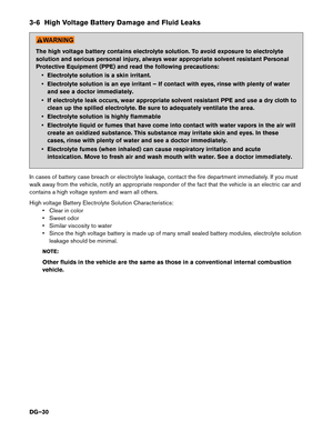
Page 21 of 46
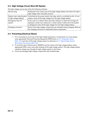
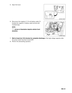
5. Open the hood.
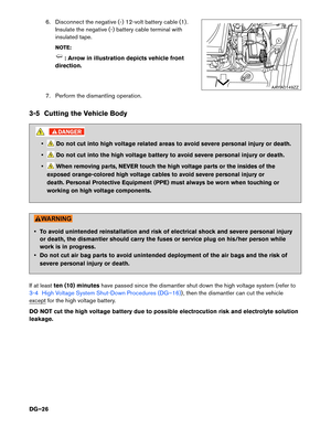
6.
Disconnect the negative (-) 12-volt battery cable (1) .
Insulate the negative (-) battery cable terminal with
insulated tape.
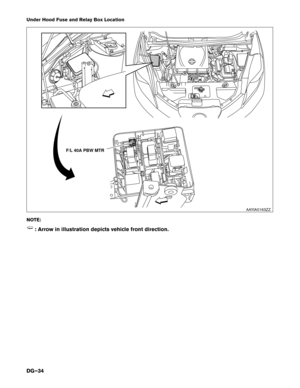
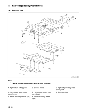
NOTE: : Arrow in illustration depicts vehicle front
direction.
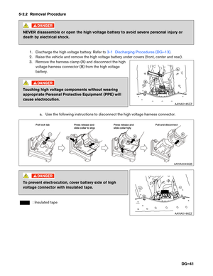
7. Wait
at least ten (10) minutes for complete discharge of the high voltage capacitor after
the power switch has been turned OFF.
8. Perform the dismantling operation. AAYIA0145ZZ
1
AAYIA0149ZZ
DG–21
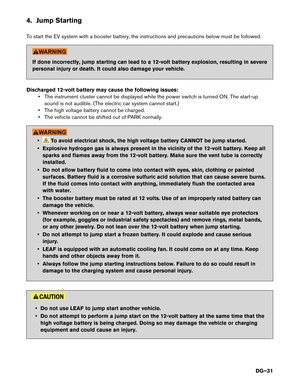
Page 22 of 46
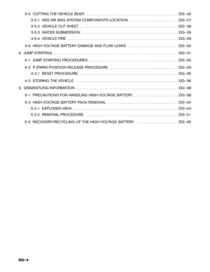
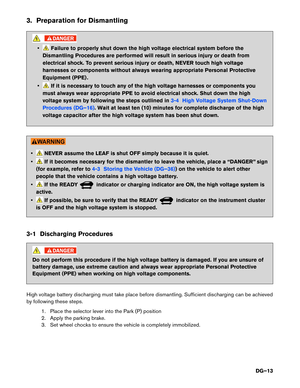
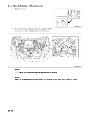
3-4.5 Alternate Procedure 1 (Remove Fuses)
1. Open the hood.
2. Press and expand the pawls (A) on the sides of the fuse box and remove the fuse box (1) from its housing.
NOTE: : Arrow in illustration depicts vehicle front direction.
NO
TE:
There is no separate fuse box cover. The bottom of the fuse box is also its cover. AAYIA0145ZZ
1A
AAYIA0150ZZ
DG–22
Page 23 of 46
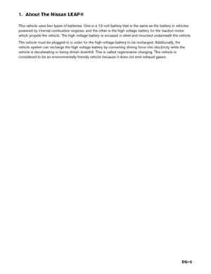
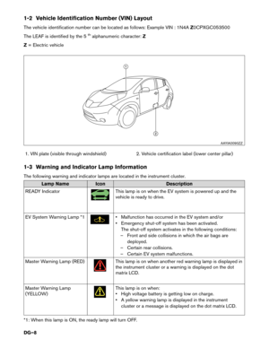
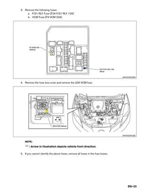
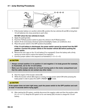
3. Remove the following fuses:
a. F/S1 RLY Fuse (F24 F/S1 RLY 15A)
b. VCM Fuse (F3 VCM 20A)
4. Remove the fuse box cover and remove the 20A VCM fuse. NOTE: : Arrow in illustration depicts vehicle front direction.
5.
If you cannot identify the above fuses, remove all fuses in the fuse boxes. F24 F/S1 RLY 15A
(Blue)F3 VCM 20A
(Y
ellow)
AAYIA0053GB20A VCM (Yellow)
AAYIA0054GB
DG–23
Page 24 of 46
 12-volt battery cable (1) .
Insulate the negative (-) battery cable terminal with
insulated tape.
NOTE: : Arrow in illustration depicts vehicle front
direction.
7. Wait")
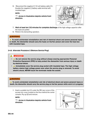
6. Disconnect the negative (-) 12-volt battery cable (1) .
Insulate the negative (-) battery cable terminal with
insulated tape.
NOTE: : Arrow in illustration depicts vehicle front
direction.
7. Wait
at least ten (10) minutes for complete discharge of the high voltage capacitor after
the fuses are pulled.
8. Perform the dismantling operation. To avoid unintended reinstallation and risk of electrical shock and severe personal injury
or
death, the dismantler should carry the fuses on his/her person and cover the fuse box
with insulated tape.
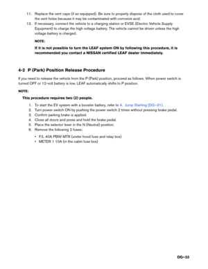
3-4.6 Alternate Procedure 2 (Remove Service Plug) • Do not remove the service plug without always wearing appropriate Personal
Protective
Equipment (PPE) to help protect the dismantler from serious injury or death
by electrical shock.
• Immediately cover the service plug socket with insulated tape. The high voltage
battery
retains high voltage power even when the service plug is removed. To avoid
electric shock, NEVER touch the terminals inside the socket.
To avoid unintended reinstallation and risk of electrical shock and severe personal injury or
death, the dismantler should carry the service plug on his/her person while work is in progress.
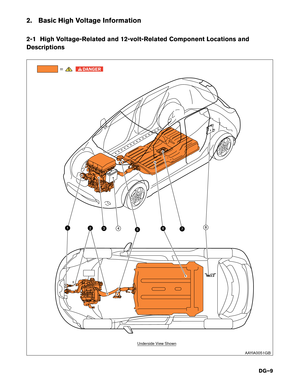
1. Insert a suitable tool (1) under the RH rear corner of the access trim cover located on the floor behind the center
console. Pry up (2) and remove.
NOTE: : Arrow in illustration depicts vehicle front
direction. 1
AAYIA0149ZZ 12
AAYIA0159ZZ
DG–24

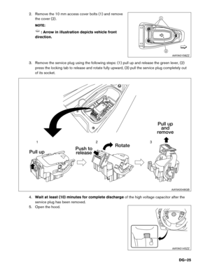

NOTE:
The quick")

 12-volt battery cable (1) .
Insulate the negative (-) battery cable terminal with
insulated tape.
NOTE: : Arrow in illustration depicts vehicle front
d")

1. Open the hood.
2. Press and expand the pawls (A) on the sides of the fuse box and remove the fuse box (1) from its housing.
NOTE: : Arrow in illustration")

b. VCM Fuse (F3 VCM 20A)
4. Remove the fuse box cover and remove the 20A VCM fuse. NOTE: : Arrow in illustration depicts vehicle fron")