2016 NISSAN FRONTIER ignition
[x] Cancel search: ignitionPage 283 of 469
IC Regulatory information
– Operation is subject to the following two con-ditions: (1) this device may not cause interfer-
ence, and (2) this device must accept any
interference, including interference that may
cause undesired operation of the device.
– This Class B digital apparatus meets all re- quirements of the Canadian Interference-
Causing Equipment Regulations.
BLUETOOTH® is a
trademark owned by
Bluetooth SIG, Inc.
and licensed to
Visteon.
USING THE SYSTEM
The system allows hands-free operation of the
Bluetooth® Hands-Free Phone System.
If the vehicle is in motion, some commands may
not be available so full attention may be given to
vehicle operation.
Initialization
When the ignition switch is placed in the ON
position, NISSAN Voice Recognition is initialized,
which takes a few seconds. If the
button is
pressed before the initialization completes, the system will announce “Hands-free phone system
not ready” and will not react to voice commands.
Operating tips
To get the best performance out of the NISSAN
Voice Recognition system, observe the following:
● Keep the interior of the vehicle as quiet as
possible. Close the windows to eliminate
surrounding noises (traffic noises, vibration
sounds, etc.) , which may prevent the system
from recognizing voice commands correctly.
● Wait until the tone sounds before speaking a
command. Otherwise, the command will not
be received properly.
● Start speaking a command within 5 seconds
after the tone sounds.
● Speak in a natural voice without pausing
between words.
Giving voice commands
To operate NISSAN Voice Recognition, press
and release the
button located on the
steering wheel. After the tone sounds, speak a
command.
The command given is picked up by the micro-
phone, and voice feedback is given when the
command is accepted. ●
If you need to hear the available commands
for the current menu again, say “Help” and
the system will repeat them.
● If a command is not recognized, the system
announces, “Command not recognized.
Please try again.” Make sure the command is
said exactly as prompted by the system and
repeat the command in a clear voice.
● If you want to go back to the previous com-
mand, you can say “Go back” or “Correc-
tion” any time the system is waiting for a
response.
● You can cancel a command when the sys-
tem is waiting for a response by saying,
“Cancel” or “Quit.” The system announces
“Cancel” and ends the NISSAN Voice Rec-
ognition session. You can also press and
hold the
button on the steering wheel
for 5 seconds at any time to end the NISSAN
Voice Recognition session. Whenever the
NISSAN Voice Recognition session is can-
celled, a double beep is played to indicate
you have exited the system.
● If you want to adjust the volume of the voice
feedback, press the Volume control
switches (+ or -) on the steering wheel while
being provided with feedback. You can also
use the radio volume control knob.
4-92Monitor, climate, audio, phone and voice recognition systems
Page 293 of 469
phone module when the ignition switch is placed
in the ON position with the connected cellular
phone turned on and carried in the vehicle.
You can register up to five different Bluetooth®
cellular phones to the in-vehicle phone module.
However, you can talk on only one cellular phone
at a time.
NISSAN Voice Recognition system supports the
phone commands, so dialing a phone number
using your voice is possible. For additional infor-
mation, refer to “NISSAN Voice Recognition Sys-
tem” in this section.
Before using the Bluetooth® Hands-Free Phone
System, refer to the following notes.● Set up the wireless connection between a
cellular phone and the in-vehicle phone
module before using the hands-free phone
system.
● Some Bluetooth® enabled cellular phones
may not be recognized by the in-vehicle
phone module. Please visit
www.nissanusa.com/bluetooth or
www.nissan.ca/bluetooth for a recom-
mended phone list and connecting instruc-
tions. ●
You will not be able to use a hands-free
phone under the following conditions:
– Your vehicle is outside of the cellular ser- vice area.
– Your vehicle is in an area where it is difficult to receive cellular signal; such as
in a tunnel, in an underground parking
garage, near a tall building or in a moun-
tainous area.
– Your cellular phone is locked to prevent it from being dialed.
● When the radio wave condition is not ideal
or ambient sound is too loud, it may be
difficult to hear the other person’s voice dur-
ing a call.
● Immediately after the ignition switch is
placed in the ON position, it may be impos-
sible to receive a call for a short period of
time.
● Do not place the cellular phone in an area
surrounded by metal or far away from the
in-vehicle phone module to prevent tone
quality degradation and wireless connection
disruption. ●
While a cellular phone is connected through
the Bluetooth® wireless connection, the
battery power of the cellular phone may dis-
charge quicker than usual. The Bluetooth®
Hands-Free Phone System cannot charge
cellular phones.
● If the hands-free phone system seems to be
malfunctioning, refer to “Troubleshooting
guide” in this section. You can also visit
www.nissanusa.com/bluetooth or
www.nissan.ca/bluetooth for troubleshoot-
ing help.
● Some cellular phones or other devices may
cause interference or a buzzing noise to
come from the audio system speakers. Stor-
ing the device in a different location may
reduce or eliminate the noise.
● Refer to the cellular phone owner’s manual
regarding the telephone charges, cellular
phone antenna and body, etc.
● The signal strength display on the monitor
will not coincide with the signal strength
display of some cellular phones.
4-102Monitor, climate, audio, phone and voice recognition systems
Page 300 of 469
The NISSAN Voice Recognition system allows
hands-free operation of the systems equipped on
this vehicle, such as the phone and navigation
systems.
To operate NISSAN Voice Recognition, press
the
button located on the steering wheel.
When prompted, speak the command for the
system you wish to activate. The command given
is picked up by the microphone and performed
when it is properly recognized. NISSAN Voice
Recognition will provide a voice response as well
as a message in the center display to inform you
of the command results.
USING THE SYSTEM
Initialization
When the ignition switch is in the ON position,
NISSAN Voice Recognition is initialized, which
takes a few seconds. When completed, the sys-
tem is ready to accept voice commands. If
the
button is pressed before the initializa-
tion completes, the system will announce: “Voice
Recognition System not ready. Please wait.”
Giving voice commands
1. Press thebutton.
2. The system announces: “Please say a cat- egory like phone or a command like points of
interest followed by a brand name”. A list of
available commands is then spoken by the
system.
3. After the tone sounds and the face icon on the display changes, speak a command.
Available commands are discussed in this
section. 4. Voice and display feedback are provided
when the command is accepted.
● If the command is not recognized, the sys-
tem announces: “Command not recog-
nized”. Repeat the command in a clear voice.
● If you want to cancel the command or go
back to the previous menu of commands,
press the
button. The system will an-
nounce: “Cancelling Voice Recognition” or
“Go back” depending on the current menu
level.
● Press the
button to move back
through the menus displayed on the screen.
● If you want to adjust the volume of the voice
feedback, use the volume control switches
on the steering wheel or the volume knob on
the control panel.
● The voice command screen can also be
accessed using the control panel display:
1. Press the [
] button.
2. Touch the “Voice Commands” key.
LHA2589
NISSAN VOICE RECOGNITION
SYSTEM (if so equipped)
Monitor, climate, audio, phone and voice recognition systems4-109
Page 305 of 469
5 Starting and driving
Precautions when starting and driving................5-2
Exhaust gas (carbon monoxide) ..................5-2
Three-way catalyst ..............................5-3
Tire Pressure Monitoring System (TPMS) ..........5-3
On-pavement and off-road driving
precautions ....................................5-6
Avoiding collision and rollover . . ..................5-6
Off-road recovery ...............................5-7
Rapid air pressure loss ..........................5-7
Drinking alcohol/drugs and driving ................5-8
Driving safety precautions .......................5-8
Ignition switch .................................... 5-10
Automatic transmission (if so equipped) ..........5-10
Manual transmission (if so equipped) ............5-11
Key positions ................................. 5-12
NISSAN Vehicle Immobilizer System
(if so equipped) ............................... 5-12
Before starting the engine ......................... 5-12
Starting the engine ............................... 5-13
Driving the vehicle ................................ 5-14
Automatic transmission (if so equipped) ..........5-14
Manual transmission (if so equipped) ............5-18
Parking brake .................................... 5-20Cruise control (if so equipped) . .
...................5-21
Precautions on cruise control ...................5-21
Cruise control operations .......................5-22
Break-in schedule ................................ 5-23
Fuel efficient driving tips ........................... 5-23
Increasing fuel economy ........................... 5-24
Using four wheel drive (4WD)
(if so equipped) .................................. 5-25
Transfer case shifting procedures . . .............5-25
Electronic locking rear differential (E-Lock) system
(if so equipped) .................................. 5-31
Parking/parking on hills ............................ 5-33
Power steering ................................... 5-34
Brake system .................................... 5-34
Brake precautions ............................. 5-34
Anti-lock Braking System (ABS) .................5-35
Active brake limited slip (ABLS) system .............5-36
Vehicle Dynamic Control (VDC) system .............5-37
Brake force distribution ........................ 5-39
Hill descent control system (if so equipped) .........5-40
Hill start assist system (if so equipped) ..............5-40
Rear sonar system (RSS) (if so equipped) ...........5-41
Cold weather driving .............................. 5-42
Page 308 of 469
THREE-WAY CATALYST
The three-way catalyst is an emission control
device installed in the exhaust system. Exhaust
gases in the three-way catalyst are burned at
high temperatures to help reduce pollutants.
WARNING
●The exhaust gas and the exhaust sys-
tem are very hot. Keep people, animals
or flammable materials away from the
exhaust system components.
● Do not stop or park the vehicle over
flammable materials such as dry grass,
waste paper or rags. They may ignite
and cause a fire.
CAUTION
●Do not use leaded gasoline. Deposits
from leaded gasoline will seriously re-
duce the three-way catalyst’s ability to
help reduce exhaust pollutants. ●
Keep your engine tuned up. Malfunc-
tions in the ignition, fuel injection, or
electrical systems can cause overrich
fuel flow into the three-way catalyst,
causing it to overheat. Do not keep driv-
ing if the engine misfires, or if notice-
able loss of performance or other un-
usual operating conditions are
detected. Have the vehicle inspected
promptly. It is recommended that you
visit a NISSAN dealer for this service.
● Avoid driving with an extremely low fuel
level. Running out of fuel could cause
the engine to misfire, damaging the
three-way catalyst.
● Do not race the engine while warming it
up.
● Do not push or tow your vehicle to start
the engine.
TIRE PRESSURE MONITORING
SYSTEM (TPMS)
Each tire, including the spare (if provided) ,
should be checked monthly when cold and in-
flated to the inflation pressure recommended by
the vehicle manufacturer on the vehicle placard
or tire inflation pressure label. (If your vehicle has
tires of a different size than the size indicated on
the vehicle placard or tire inflation pressure label, you should determine the proper tire inflation
pressure for those tires.)
As an added safety feature, your vehicle has been
equipped with a Tire Pressure Monitoring System
(TPMS) that illuminates a low tire pressure telltale
when 1 or more of your tires is significantly under-
inflated. Accordingly, when the low tire pressure
telltale illuminates, you should stop and check
your tires as soon as possible, and inflate them to
the proper pressure. Driving on a significantly
under-inflated tire causes the tire to overheat and
can lead to tire failure. Under-inflation also re-
duces fuel efficiency and tire tread life, and may
affect the vehicle’s handling and stopping ability.
Please note that the TPMS is not a substitute for
proper tire maintenance, and it is the driver’s
responsibility to maintain correct tire pressure,
even if under-inflation has not reached the level to
trigger illumination of the TPMS low tire pressure
telltale.
Your vehicle has also been equipped with a
TPMS malfunction indicator to indicate when the
system is not operating properly. The TPMS mal-
function indicator is combined with the low tire
pressure telltale. When the system detects a
malfunction, the telltale will flash for approxi-
mately 1 minute and then remain continuously
illuminated. This sequence will continue upon
subsequent vehicle start-ups as long as the mal-
Starting and driving5-3
Page 309 of 469
function exists. When the malfunction indicator is
illuminated, the system may not be able to detect
or signal low tire pressure as intended. TPMS
malfunctions may occur for a variety of reasons,
including the installation of replacement or alter-
nate tires or wheels on the vehicle that prevent
the TPMS from functioning properly. Always
check the TPMS malfunction telltale after replac-
ing 1 or more tires or wheels on your vehicle to
ensure that the replacement or alternate tires and
wheels allow the TPMS to continue to function
properly.
Additional information:● Since the spare tire is not equipped with the
TPMS, the TPMS does not monitor the tire
pressure of the spare tire.
● The TPMS will activate only when the vehicle
is driven at speeds above 16 mph (25 km/h).
Also, this system may not detect a sudden
drop in tire pressure (for example a flat tire
while driving) . ●
The low tire pressure warning light does not
automatically turn off when the tire pressure
of your tires are adjusted. After the tires are
inflated to the recommended pressure, the
vehicle must be driven at speeds above
16 mph (25 km/h) to activate the TPMS and
turn off the low tire pressure warning light.
Use a tire pressure gauge to check the tire
pressure.
● The CHECK TIRE PRES (pressure) warning
message is displayed in the odometer when
the low tire pressure warning light is illumi-
nated and low tire pressure is detected. The
CHECK TIRE PRES warning message turns
off when the low tire pressure warning light
turns off. The low tire pressure warning light
remains illuminated until the tires are inflated
to the recommended COLD tire pressure.
The CHECK TIRE PRES warning message
is displayed each time the ignition switch is
placed in the ON position as long as the low
tire pressure warning light remains illumi-
nated. For additional information, refer to
“Check tire pressure warning message” in
the “Instruments and controls” section of this
manual. ●
The CHECK TIRE PRES warning is not dis-
played if the low tire pressure warning light
illuminates to indicate a TPMS malfunction.
The CHECK TIRE PRESSURE warning ap-
pears each time the ignition switch is placed
in the ON position as long as the low tire
pressure warning light remains illuminated.
● Tire pressure rises and falls depending on
the heat caused by the vehicle’s operation
and the outside temperature. Do not reduce
the tire pressure after driving because the
tire pressure rises after driving. Low outside
temperature can lower the temperature of
the air inside the tire which can cause a
lower tire inflation pressure. This may cause
the low tire pressure warning light to illumi-
nate. If the warning light illuminates, check
the tire pressure for all four tires.
● The Tire and Loading Information label (also
referred to as the vehicle placard or tire
inflation pressure label) is located in the
driver’s door opening.
For additional information, refer to “Low tire pres-
sure warning light” in the “Instruments and con-
trols” section and “Tire Pressure Monitoring Sys-
tem (TPMS)” in the “In case of emergency”
section of this manual.
5-4Starting and driving
Page 315 of 469
●Always use tires of the same type, size,
brand, construction (bias, bias-belted,
or radial) , and tread pattern on all four
wheels. Install tire chains on the rear
wheels when driving on slippery roads
and drive carefully.
● Be sure to check the brakes immedi-
ately after driving in mud or water. For
additional information, refer to “Wet
brakes” in this section.
● Avoid parking your vehicle on steep
hills. If you get out of the vehicle and it
rolls forward, backward or sideways,
you could be injured.
● Whenever you drive off-road through
sand, mud or water as deep as the
wheel hub, more frequent maintenance
may be required. For additional infor-
mation, refer to “Periodic maintenance”
in the “NISSAN Service and Mainte-
nance Guide.WARNING
●Never remove the ignition key or place
the ignition switch in the LOCK position
while driving. The steering wheel will
lock (for models with a steering lock
mechanism) . This may cause the driver
to lose control of the vehicle and could
result in serious vehicle damage or per-
sonal injury.
AUTOMATIC TRANSMISSION (if so
equipped)
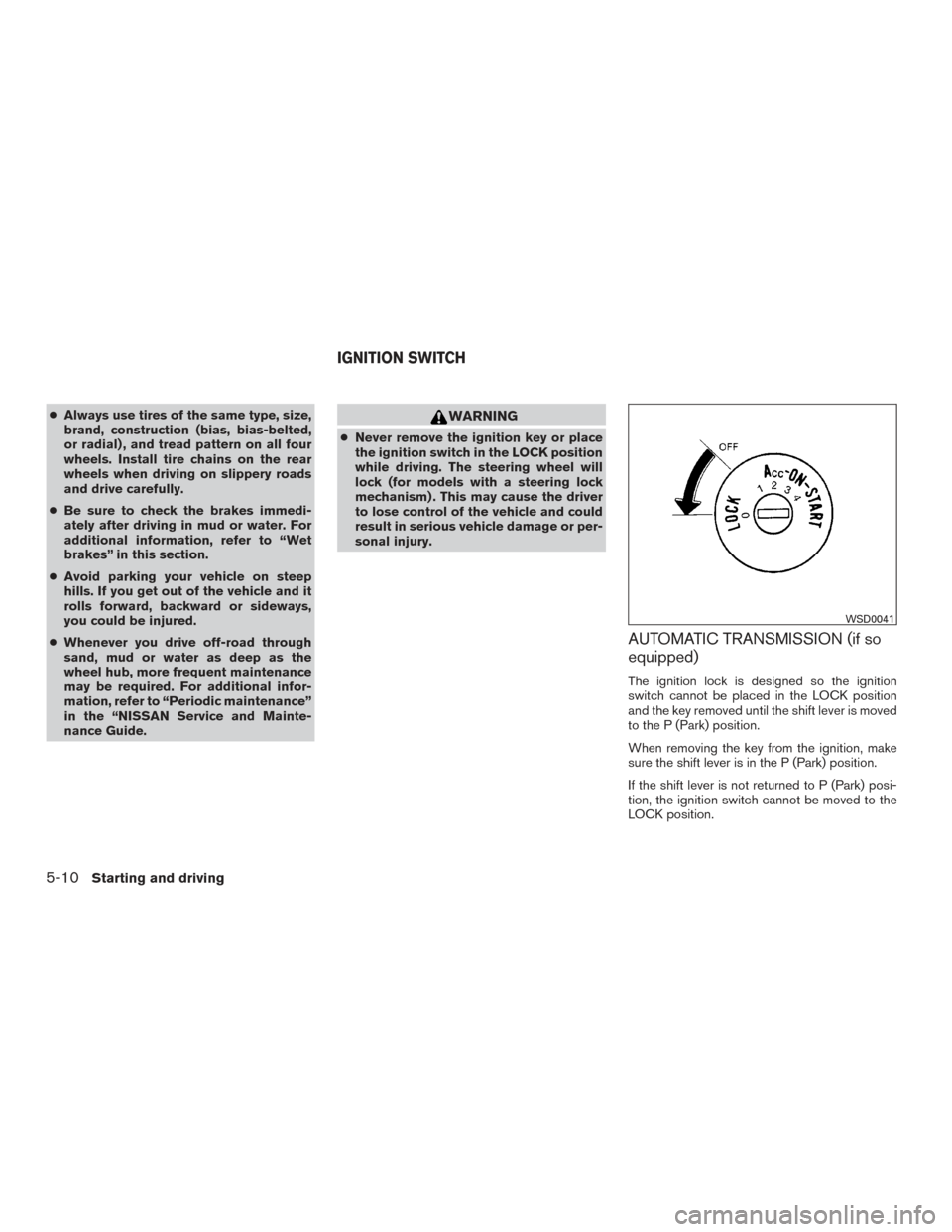
The ignition lock is designed so the ignition
switch cannot be placed in the LOCK position
and the key removed until the shift lever is moved
to the P (Park) position.
When removing the key from the ignition, make
sure the shift lever is in the P (Park) position.
If the shift lever is not returned to P (Park) posi-
tion, the ignition switch cannot be moved to the
LOCK position.
WSD0041
IGNITION SWITCH
5-10Starting and driving
Page 316 of 469
To remove the key from the ignition switch:1. Shift the shift lever to the P (Park) position with the ignition switch in the ON position.
2. Place the ignition switch to the LOCK posi- tion.
3. Remove the key from the ignition.
If the shift lever is shifted to the P (Park) position
after the ignition switch is placed in the OFF
position or when the ignition switch cannot be
turned to the LOCK position, proceed as follows
to remove the key. 1. Move the shift lever into the P (Park) posi- tion.
2. Turn the ignition key slightly toward the ON position.
3. Turn the key to the LOCK position.
4. Remove the key.
The shift lever is designed so it cannot moved out
of P (Park) and into any of the other gear posi-
tions if the ignition key is turned to OFF position
or if the key is removed from the switch.
The shift lever can be moved if the ignition
switch is in the ON position and the foot
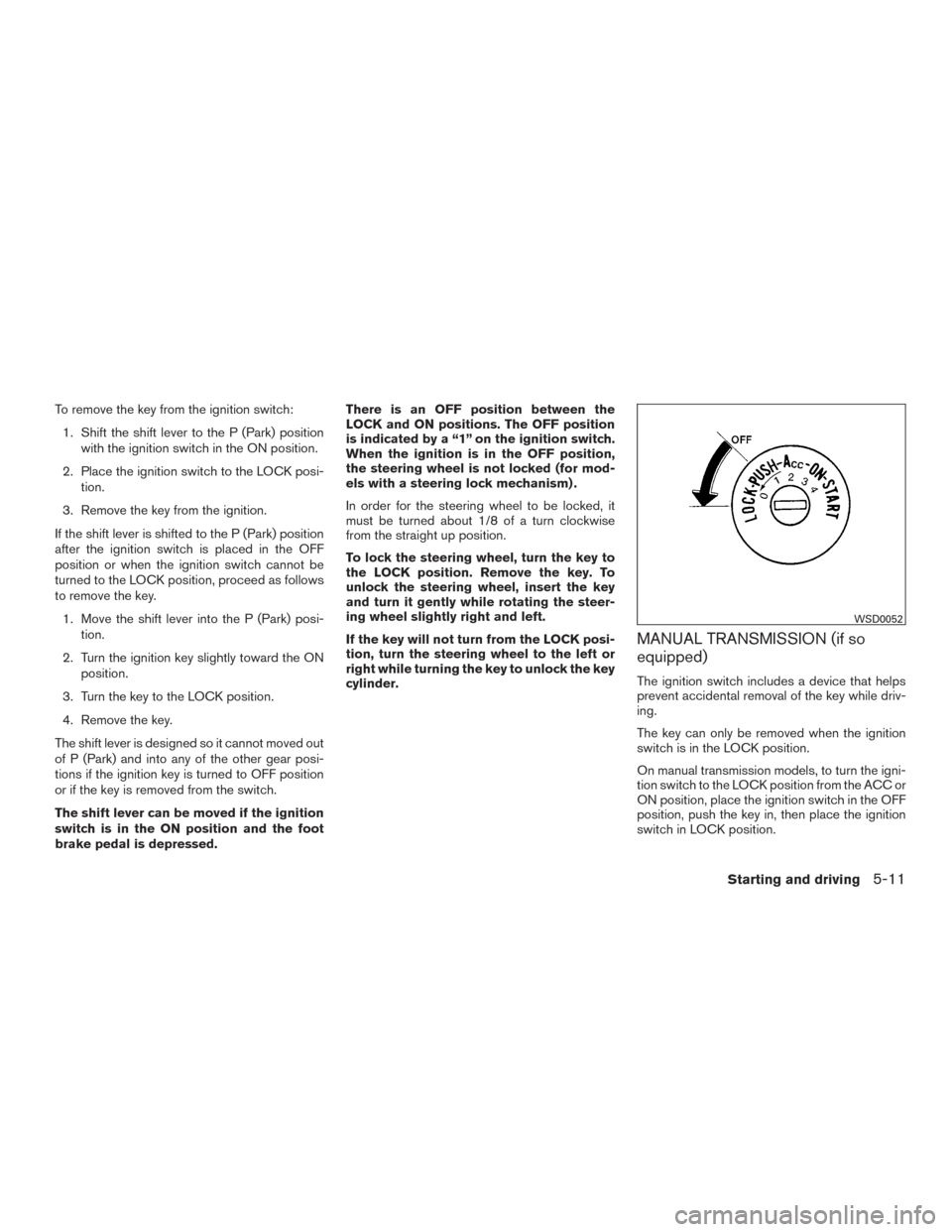
brake pedal is depressed. There is an OFF position between the
LOCK and ON positions. The OFF position
is indicated by a “1” on the ignition switch.
When the ignition is in the OFF position,
the steering wheel is not locked (for mod-
els with a steering lock mechanism) .
In order for the steering wheel to be locked, it
must be turned about 1/8 of a turn clockwise
from the straight up position.
To lock the steering wheel, turn the key to
the LOCK position. Remove the key. To
unlock the steering wheel, insert the key
and turn it gently while rotating the steer-
ing wheel slightly right and left.
If the key will not turn from the LOCK posi-
tion, turn the steering wheel to the left or
right while turning the key to unlock the key
cylinder.
MANUAL TRANSMISSION (if so
equipped)
The ignition switch includes a device that helps
prevent accidental removal of the key while driv-
ing.
The key can only be removed when the ignition
switch is in the LOCK position.
On manual transmission models, to turn the igni-
tion switch to the LOCK position from the ACC or
ON position, place the ignition switch in the OFF
position, push the key in, then place the ignition
switch in LOCK position.
WSD0052
Starting and driving5-11