Page 392 of 469

CAUTION
●Do not ground accessories directly to
the battery terminal. Doing so will by-
pass the variable voltage control sys-
tem and the vehicle battery may not
charge completely.
● Use electrical accessories with the en-
gine running to avoid discharging the
vehicle battery.
Your vehicle is equipped with a variable voltage
control system. This system measures the
amount of electrical discharge from the battery
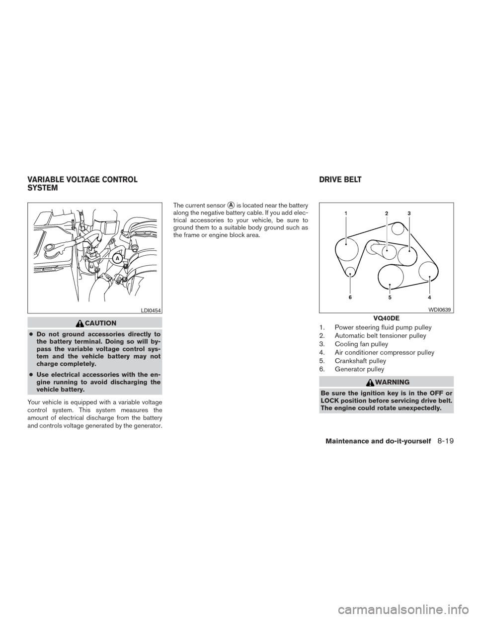
and controls voltage generated by the generator. The current sensor
�Ais located near the battery
along the negative battery cable. If you add elec-
trical accessories to your vehicle, be sure to
ground them to a suitable body ground such as
the frame or engine block area.
1. Power steering fluid pump pulley
2. Automatic belt tensioner pulley
3. Cooling fan pulley
4. Air conditioner compressor pulley
5. Crankshaft pulley
6. Generator pulley
WARNING
Be sure the ignition key is in the OFF or
LOCK position before servicing drive belt.
The engine could rotate unexpectedly.
LDI0454
VQ40DE
WDI0639
VARIABLE VOLTAGE CONTROL
SYSTEM DRIVE BELT
Maintenance and do-it-yourself8-19
Page 398 of 469
Proper brake inspection intervals should
be followed.For additional information regard-
ing brake inspections, refer to the appropriate
maintenance schedule information in the
“NISSAN Service and Maintenance Guide”.
If any electrical equipment does not operate,
check for an open fuse.
Fuses are used in the passenger and engine
compartment. Spare fuses are provided and can
be found in the passenger compartment fuse
box.
When installing a fuse make sure the fuse is
installed in the fuse box securely.
ENGINE COMPARTMENT
WARNING
Never use a fuse of a higher or lower
amperage rating than specified on the
fuse box cover. This could damage the
electrical system or electronic control
units or cause a fire.
If any electrical equipment does not come on,
check for an open fuse. 1. Be sure the ignition switch and the headlight switch are OFF.
2. Open the engine hood.
LDI2385LDI2838
FUSES
Maintenance and do-it-yourself8-25
Page 400 of 469
If any electrical equipment does not operate,
check for an open fuse.1. Be sure the ignition switch and the headlight switch are OFF.
2. Pull the fuse box cover to remove.
3. Remove the fuse with the fuse puller.
4. If the fuse is open
�A, replace it with an
equivalent good fuse
�B.
5. Reverse step 2 to reinstall fuse box cover.
6. If a new fuse also opens, have the electrical system checked and repaired. It is recom-
mended that you visit a NISSAN dealer for
this service.Extended storage switch
If any electrical equipment does not operate,
remove the extended storage switch and check
for an open fuse.
NOTE:
The extended storage switch is used for
long term vehicle storage. Even if the ex-
tended storage switch is broken it is not
necessary to replace it. Replace only the
open fuse in the switch with a new fuse.
LDI0456LDI2736
Maintenance and do-it-yourself8-27
Page 401 of 469
How to replace the extended storage switch:1. To remove the extended storage switch, be sure the ignition switch is in the OFF or
LOCK position.
2. Be sure the headlight switch is in the OFF position.
3. Remove the fuse box cover.
4. Pinch the locking tabs
�Afound on each
side of the storage switch.
5. Pull the storage switch straight out from the fuse box
�B.
CAUTION
Be careful not to allow children to swallow
the battery or removed parts.
BATTERY REPLACEMENT
8-28Maintenance and do-it-yourself
Page 424 of 469

Incorrect ignition timing may result in spark
knock, after-run and/or overheating, which may
cause excessive fuel consumption or engine
damage. If any of the above symptoms are en-
countered, have your vehicle checked. It is rec-
ommended that you visit a NISSAN dealer for
servicing.
However, now and then you may notice
light spark knock for a short time while
accelerating or driving up hills. This is not a
cause for concern, because you get the
greatest fuel benefit when there is light
spark knock for a short time under heavy
engine load.
ENGINE OIL AND OIL FILTER
RECOMMENDATIONS
Selecting the correct oil
It is essential to choose the correct grade, quality
and viscosity engine oil to ensure satisfactory
engine life and performance. For additional infor-
mation, refer to “Recommended fluids/lubricants
and capacities” in this section. NISSAN recom-
mends the use of an energy conserving oil in
order to improve fuel economy.
Select only engine oils that meet the American
Petroleum Institute (API) certification or Interna-
tional Lubricant Standardization and ApprovalCommittee (ILSAC) certification and SAE vis-
cosity standard. These oils have the API certifica-
tion mark on the front of the container. Oils which
do not have the specified quality label should not
be used as they could cause engine damage.Oil additives
NISSAN does not recommend the use of oil
additives. The use of an oil additive is not neces-
sary when the proper oil type is used and main-
tenance intervals are followed.
Oil which may contain foreign matter or has been
previously used should not be used.
LTI2061
Technical and consumer information9-7
Page 426 of 469
ENGINE
ModelQR25DE VQ40DE
Type Gasoline, 4-cycle, DOHC Gasoline, 4-cycle, DOHC
Cylinder arrangement 4-cylinder in-line6-cylinder, V-block, Slanted at 60°
Bore x Stroke in (mm) 3.5 x 3.9 (89.0 x 100.0)3.760 x 3.622 (95.5 x 92)
Displacement cu in (cm
3) 151.82 (2,488)241.30 (3,954)
Firing order 1–3–4–21–2–3–4–5–6
Idle speed
M/T
A/T in N (Neutral) position Refer to the “Emission control information label” on the underside of the hood.
Ignition timing (degree B.T.D.C. at idle
speed)
CO%atidle
Spark plug Standard PLZKAR6A-11DILFR5A-11
Spark plug gap (Nominal) in (mm) 0.043 (1.1)0.043 (1.1)
Camshaft operation Timing chainTiming chain
This spark ignition system complies with the Canadian standard ICES-002.
SPECIFICATIONS
Technical and consumer information9-9
Page 449 of 469

Bumper towing
The Genuine NISSAN step bumper has provi-
sions to install a trailer hitch ball and is designed
to tow trailers of a maximum weight of 3,500 lb
(1,588 kg).
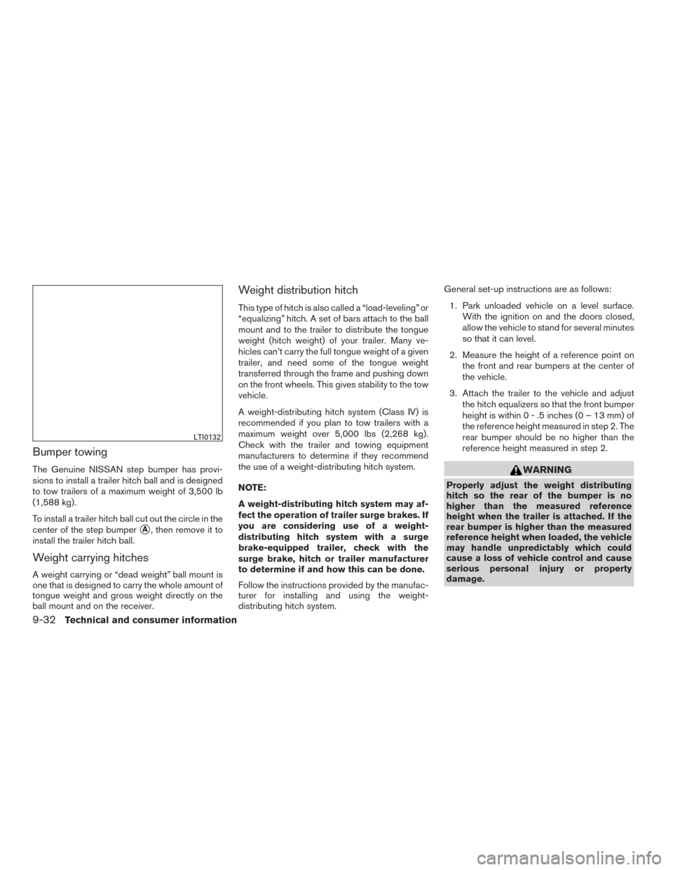
To install a trailer hitch ball cut out the circle in the
center of the step bumper
�A, then remove it to
install the trailer hitch ball.
Weight carrying hitches
A weight carrying or “dead weight” ball mount is
one that is designed to carry the whole amount of
tongue weight and gross weight directly on the
ball mount and on the receiver.
Weight distribution hitch
This type of hitch is also called a “load-leveling” or
“equalizing” hitch. A set of bars attach to the ball
mount and to the trailer to distribute the tongue
weight (hitch weight) of your trailer. Many ve-
hicles can’t carry the full tongue weight of a given
trailer, and need some of the tongue weight
transferred through the frame and pushing down
on the front wheels. This gives stability to the tow
vehicle.
A weight-distributing hitch system (Class IV) is
recommended if you plan to tow trailers with a
maximum weight over 5,000 lbs (2,268 kg).
Check with the trailer and towing equipment
manufacturers to determine if they recommend
the use of a weight-distributing hitch system.
NOTE:
A weight-distributing hitch system may af-
fect the operation of trailer surge brakes. If
you are considering use of a weight-
distributing hitch system with a surge
brake-equipped trailer, check with the
surge brake, hitch or trailer manufacturer
to determine if and how this can be done.
Follow the instructions provided by the manufac-
turer for installing and using the weight-
distributing hitch system. General set-up instructions are as follows:
1. Park unloaded vehicle on a level surface. With the ignition on and the doors closed,
allow the vehicle to stand for several minutes
so that it can level.
2. Measure the height of a reference point on the front and rear bumpers at the center of
the vehicle.
3. Attach the trailer to the vehicle and adjust the hitch equalizers so that the front bumper
height is within0-.5inches (0 – 13 mm) of
the reference height measured in step 2. The
rear bumper should be no higher than the
reference height measured in step 2.
WARNING
Properly adjust the weight distributing
hitch so the rear of the bumper is no
higher than the measured reference
height when the trailer is attached. If the
rear bumper is higher than the measured
reference height when loaded, the vehicle
may handle unpredictably which could
cause a loss of vehicle control and cause
serious personal injury or property
damage.
LTI0132
9-32Technical and consumer information
Page 457 of 469

Additional information concerning motor
vehicle safety may be obtained from Trans-
port Canada’s Road Safety Information
Centre at 1-800-333-0371 or online at
www.tc.gc.ca/roadsafety (English speak-
ers) or www.tc.gc.ca/securiteroutiere
(French speakers) .
To notify NISSAN of any safety concerns
please contact our Consumer Information
Centre toll free at 1-800-387-0122.
WARNING
A vehicle equipped with Four-Wheel Drive
(4WD) should never be tested using a two
wheel dynamometer (such as the dyna-
mometers used by some states for emis-
sions testing) , or similar equipment. Make
sure you inform the test facility personnel
that your vehicle is equipped with 4WD
before it is placed on a dynamometer.
Using the wrong test equipment may re-
sult in transmission damage or unex-
pected vehicle movement which could re-
sult in serious vehicle damage or personal
injury.
Due to legal requirements in some states and
Canadian Provinces, your vehicle may be re-
quired to be in what is called the “ready condi-
tion” for an Inspection/Maintenance (I/M) test of
the emission control system.
The vehicle is set to the “ready condition” when it
is driven through certain driving patterns. Usually,
the ready condition can be obtained by ordinary
usage of the vehicle. If a powertrain system component is repaired or
the battery is disconnected, the vehicle may be
reset to a “not ready” condition. Before taking the
I/M test, check the vehicle’s
inspection/maintenance test readiness condi-
tion. Place the ignition switch in the ON position
without starting the engine. If the Malfunction
Indicator Light (MIL) comes on steady for 20 sec-
onds and then blinks for 10 seconds, the I/M test
condition is “not ready”. If the MIL does not blink
after 20 seconds, the I/M test condition is
“ready”. It is recommended that you visit a
NISSAN dealer to set the “ready condition” or to
prepare the vehicle for testing.
READINESS FOR INSPECTION/
MAINTENANCE (I/M) TEST
9-40Technical and consumer information