2016 NISSAN 370Z COUPE clock
[x] Cancel search: clockPage 174 of 428
screen off, the screen turns on for further
operation. The screen will turn off automatically
5 seconds after the operation is finished.
To turn on the screen, set this item to the ON
position, or push and hold the “
OFF”
button.
. Brightness/Contrast/Background Color
To adjust the brightness and contrast of the
screen, select the “Brightness” or “Contrast”
key.
Then, you can adjust the brightness and contrast
using the multi-function controller.
For information on the “Background Color” key,
refer to the separate Navigation System Own-
er’s Manual.
For Roadster models:
Depending on the driver’s seat position, the
display could be hard to read. Adjust the
brightness and contrast of the display on the
setting screen.
Color Theme:
Choose the theme color of the menu screen
from “Black”, “Blue” or “Red”.
SAA2487
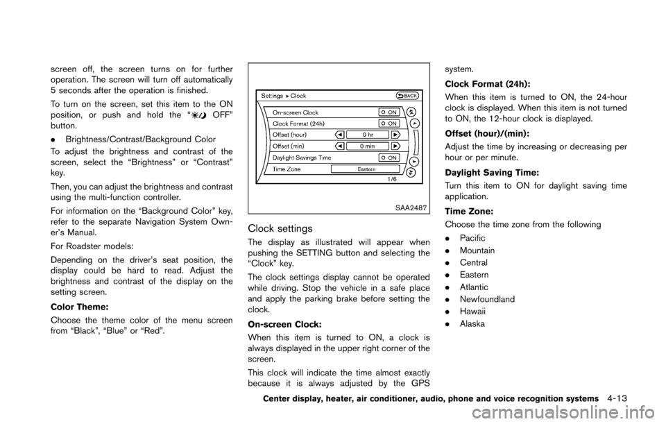
Clock settings
The display as illustrated will appear when
pushing the SETTING button and selecting the
“Clock” key.
The clock settings display cannot be operated
while driving. Stop the vehicle in a safe place
and apply the parking brake before setting the
clock.
On-screen Clock:
When this item is turned to ON, a clock is
always displayed in the upper right corner of the
screen.
This clock will indicate the time almost exactly
because it is always adjusted by the GPS system.
Clock Format (24h):
When this item is turned to ON, the 24-hour
clock is displayed. When this item is not turned
to ON, the 12-hour clock is displayed.
Offset (hour)/(min):
Adjust the time by increasing or decreasing per
hour or per minute.
Daylight Saving Time:
Turn this item to ON for daylight saving time
application.
Time Zone:
Choose the time zone from the following
.
Pacific
. Mountain
. Central
. Eastern
. Atlantic
. Newfoundland
. Hawaii
. Alaska
Center display, heater, air conditioner, audio, phone and voice recognition systems4-13
Page 187 of 428
4-26Center display, heater, air conditioner, audio, phone and voice recognition systems
.The temperature of the passenger compart-
ment will be maintained automatically. Air
flow distribution and fan speed are also
controlled automatically.
A visible mist may be seen coming from the
ventilators in hot, humid conditions as the air is
cooled rapidly. This does not indicate a mal-
function.
Dehumidified defrosting or defogging:
1. Turn the “
” fan speed control dial to the
desired position.
2. Turn the air flow control dial to the “
”
position.
3. Turn the temperature control dial to set the desired temperature.
.To quickly remove ice from the outside ofthe windows, turn the “” fan speed
control dial to the maximum position.
.As soon as possible after the windshield is clean, turn the air flow control dial to
the “AUTO” position to return to the auto
mode.
.When the air flow control dial is turned tothe “”or“” position, the air
conditioner will automatically be turned
on at outside temperatures above 238F
(�í58C) to defog the windshield, and the
air recirculation mode will automatically
be turned off. Outside air is drawn into the passenger
compartment to improve the defogging
performance.
Manual operation
Fan speed control:
Turn the “
” fan speed control dial clockwise
(+) or counterclockwise (�í) to manually control
the fan speed.
Turn the dial to the “AUTO” position to return to
automatic control of the fan speed.
Temperature control:
Turn the temperature control dial to set the
desired temperature.
. The temperature can be set within the
following range.
— For U.S.: 60 to 908F (16 to 328C)
— For Canada: 64 to 908F (18 to 328C)
Air recirculation:
Push the “
” intake air control button to
recirculate interior air inside the vehicle. The
indicator light on the “
” side will come on.
The air recirculation mode cannot be activated
when the air conditioner is in the front defrosting
mode “
”.
Outside air circulation:
Push the “
” intake air control button to draw outside air into the passenger compart-
ment. The indicator light on the “
” side will
come on.
Automatic intake air control:
In the AUTO mode, the intake air will be
controlled automatically. To manually control
the intake air, push the “
” intake air
control button. To return to the automatic control
mode, push the “
” intake air control
button for approximately 2 seconds. The indi-
cator lights (both air recirculation and outside air
circulation sides) will flash twice, and then the
intake air will be controlled automatically.
Air flow control:
Turning the air flow control dial selects the air
outlet to:
: Air flows from center and side ventilators.
: Air flows from center and side ventilators and foot outlets.
: Air flows mainly from foot outlets.
: Air flows from defroster and foot outlets.
: Air flows mainly from defroster outlets.
Page 204 of 428
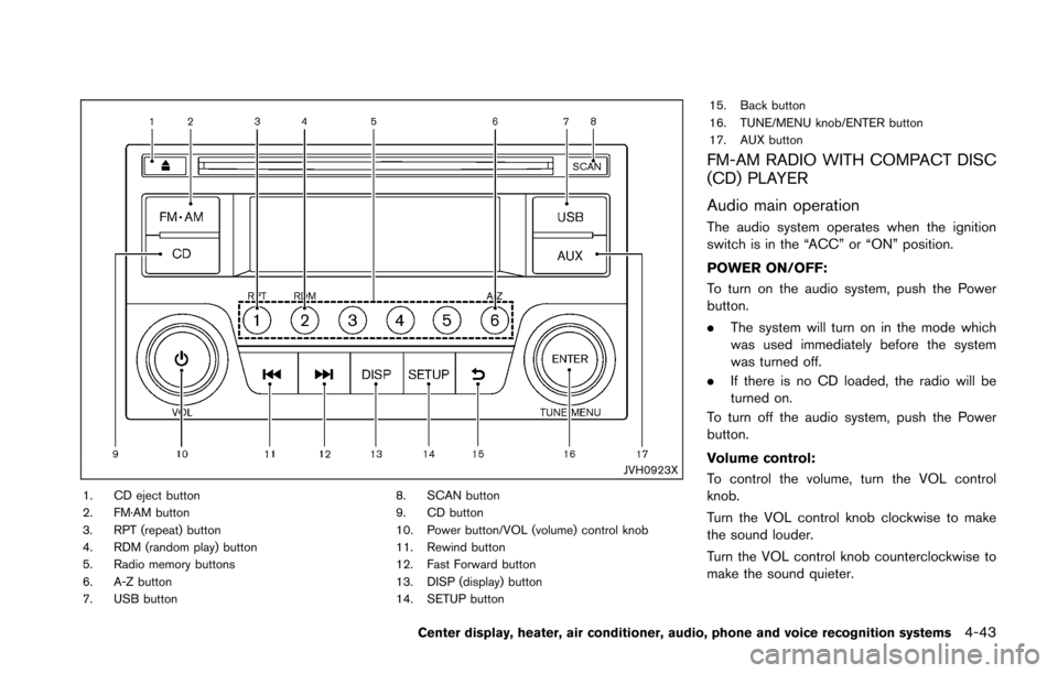
JVH0923X
1. CD eject button
2. FM·AM button
3. RPT (repeat) button
4. RDM (random play) button
5. Radio memory buttons
6. A-Z button
7. USB button8. SCAN button
9. CD button
10. Power button/VOL (volume) control knob
11. Rewind button
12. Fast Forward button
13. DISP (display) button
14. SETUP button15. Back button
16. TUNE/MENU knob/ENTER button
17. AUX button
FM-AM RADIO WITH COMPACT DISC
(CD) PLAYER
Audio main operation
The audio system operates when the ignition
switch is in the “ACC” or “ON” position.
POWER ON/OFF:
To turn on the audio system, push the Power
button.
.
The system will turn on in the mode which
was used immediately before the system
was turned off.
. If there is no CD loaded, the radio will be
turned on.
To turn off the audio system, push the Power
button.
Volume control:
To control the volume, turn the VOL control
knob.
Turn the VOL control knob clockwise to make
the sound louder.
Turn the VOL control knob counterclockwise to
make the sound quieter.
Center display, heater, air conditioner, audio, phone and voice recognition systems4-43
Page 205 of 428
4-44Center display, heater, air conditioner, audio, phone and voice recognition systems
SETUP button:
To configure Audio, Clock, Language or Scroll
direction settings, perform the following proce-
dure:
1. Push the SETUP button.
2. Push the ENTER button.
3. Turn the TUNE/MENU knob clockwise orcounterclockwise, the display will appear in
the following order:
Audio �œClock �œLanguage �œScroll
Direction
After the desired levels have been set, push
either the back button repeatedly, the SETUP
button, or wait for 8 seconds without pushing
any buttons to exit the menu screen.
Audio adjustments:
Push the SETUP button to enter the setup menu
screen then select Audio by using TUNE/MENU
knob.
Each time the ENTER button is pushed, the
mode will change as follows:
Bass ?Treble ?Fade ?Balance ?AUX VOL
? SPD VOL ?Audio (setup menu screen)
Turn the TUNE/MENU knob clockwise or
counterclockwise to adjust the following items
and push the ENTER button to confirm. Bass control:
Use this control to enhance or attenuate bass
response sound.
Treble control:
Use this control to enhance or attenuate the
treble.
Fade control:
Use this control to adjust the balance of the
volume between the front and rear (if so
equipped) speakers.
Balance control:
Use this control to adjust the balance of the
volume between the left and right speakers.
AUX VOL (Auxiliary volume) control:
Use this control to adjust the volume output from
the auxiliary source.
SPD VOL (Speed volume) control:
This mode controls the volume output from the
speakers automatically in relation to vehicle
speed.
Adjusting the setting to 0 (zero) turns off the
speed volume feature.
Clock setting:
Push the SETUP button to enter the setup menu
screen then select Clock.
Turn the TUNE/MENU knob, the mode will change as follows:
Set Time
�œON/OFF �œClock Format �œSet
time
Set Time:
Select Set Time then adjust the clock as follows:
1. The hour display will start flashing. Turn the TUNE/MENU knob to adjust the hour and
push the ENTER button.
2. The minute display will start flashing. Turn the TUNE/MENU knob to adjust the minute
and push the ENTER button to finish the
clock adjustment.
ON/OFF:
Set the clock display between on or off when the
audio unit is turned off. If set in the ON position,
the clock will be displayed when the audio unit is
turned off either by pushing the power button or
when the ignition switch is placed in the “OFF”
position.
Clock Format:
Switch the clock display between 24-hour mode
and 12-hour clock mode.
Language setting:
Push the SETUP button to enter the setup menu
screen then select Language.
Select the appropriate language and push the
ENTER button. Upon completion, the screen will
Page 235 of 428
4-74Center display, heater, air conditioner, audio, phone and voice recognition systems
SAA2374
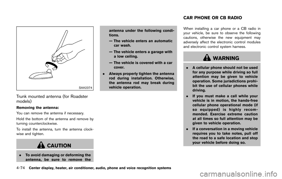
Trunk mounted antenna (for Roadster
models)
Removing the antenna:
You can remove the antenna if necessary.
Hold the bottom of the antenna and remove by
turning counterclockwise.
To install the antenna, turn the antenna clock-
wise and tighten.
CAUTION
.To avoid damaging or deforming the
antenna, be sure to remove the antenna under the following condi-
tions.
— The vehicle enters an automatic
car wash.
— The vehicle enters a garage with a low ceiling.
— The vehicle is covered with a car cover.
. Always properly tighten the antenna
rod during installation. Otherwise,
the antenna rod may break during
vehicle operation. When installing a car phone or a CB radio in
your vehicle, be sure to observe the following
cautions, otherwise the new equipment may
adversely affect the electronic control modules
and electronic control system harness.
WARNING
.
A cellular phone should not be used
for any purpose while driving so full
attention may be given to vehicle
operation. Some jurisdictions prohi-
bit the use of cellular phones while
driving.
. If you must make a call while your
vehicle is in motion, the hands-free
cellular phone operational mode (if
so equipped) is highly recom-
mended. Exercise extreme caution
at all times so full attention may be
given to vehicle operation.
. If a conversation in a moving vehicle
requires you to take notes, pull off
the road to a safe location and stop
your vehicle before doing so.
CAR PHONE OR CB RADIO
Page 324 of 428
SCE0844Without subwoofer
SCE0807With subwoofer
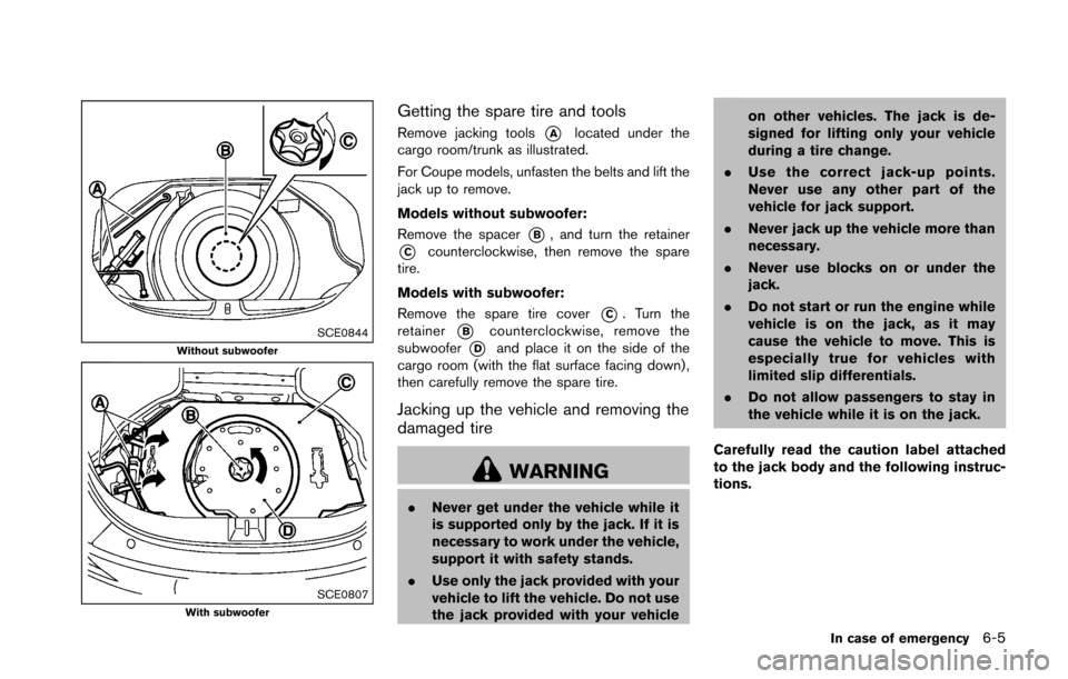
Getting the spare tire and tools
Remove jacking tools*Alocated under the
cargo room/trunk as illustrated.
For Coupe models, unfasten the belts and lift the
jack up to remove.
Models without subwoofer:
Remove the spacer
*B, and turn the retainer
*Ccounterclockwise, then remove the spare
tire.
Models with subwoofer:
Remove the spare tire cover
*C. Turn the
retainer
*Bcounterclockwise, remove the
subwoofer
*Dand place it on the side of the
cargo room (with the flat surface facing down) ,
then carefully remove the spare tire.
Jacking up the vehicle and removing the
damaged tire
WARNING
. Never get under the vehicle while it
is supported only by the jack. If it is
necessary to work under the vehicle,
support it with safety stands.
. Use only the jack provided with your
vehicle to lift the vehicle. Do not use
the jack provided with your vehicle on other vehicles. The jack is de-
signed for lifting only your vehicle
during a tire change.
. Use the correct jack-up points.
Never use any other part of the
vehicle for jack support.
. Never jack up the vehicle more than
necessary.
. Never use blocks on or under the
jack.
. Do not start or run the engine while
vehicle is on the jack, as it may
cause the vehicle to move. This is
especially true for vehicles with
limited slip differentials.
. Do not allow passengers to stay in
the vehicle while it is on the jack.
Carefully read the caution label attached
to the jack body and the following instruc-
tions.
In case of emergency6-5
Page 325 of 428
6-6In case of emergency
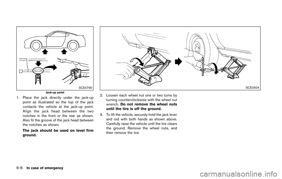
SCE0790Jack-up point
1. Place the jack directly under the jack-uppoint as illustrated so the top of the jack
contacts the vehicle at the jack-up point.
Align the jack head between the two
notches in the front or the rear as shown.
Also fit the groove of the jack head between
the notches as shown.
The jack should be used on level firm
ground.
SCE0504
2. Loosen each wheel nut one or two turns by
turning counterclockwise with the wheel nut
wrench. Do not remove the wheel nuts
until the tire is off the ground.
3. To lift the vehicle, securely hold the jack lever and rod with both hands as shown above.
Carefully raise the vehicle until the tire clears
the ground. Remove the wheel nuts, and
then remove the tire.
Page 330 of 428
JVE0014X
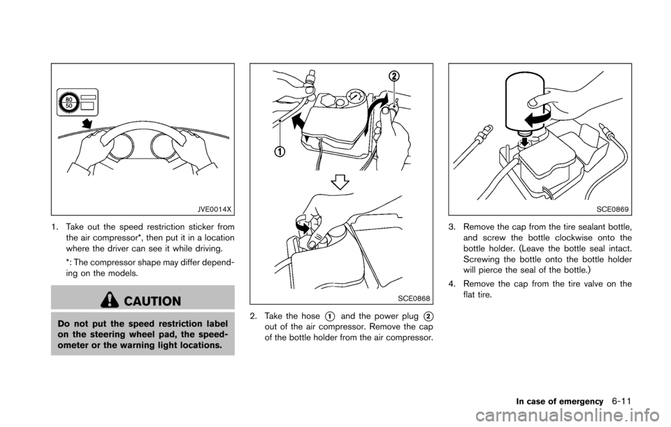
1. Take out the speed restriction sticker fromthe air compressor*, then put it in a location
where the driver can see it while driving.
*: The compressor shape may differ depend-
ing on the models.
CAUTION
Do not put the speed restriction label
on the steering wheel pad, the speed-
ometer or the warning light locations.
SCE0868
2. Take the hose*1and the power plug*2out of the air compressor. Remove the cap
of the bottle holder from the air compressor.
SCE0869
3. Remove the cap from the tire sealant bottle,and screw the bottle clockwise onto the
bottle holder. (Leave the bottle seal intact.
Screwing the bottle onto the bottle holder
will pierce the seal of the bottle.)
4. Remove the cap from the tire valve on the flat tire.
In case of emergency6-11