2016 MITSUBISHI OUTLANDER SPORT steering wheel
[x] Cancel search: steering wheelPage 61 of 398
Supplemental Restraint System (SRS) - airbag
Seat and restraint systems 4-41
4
N00408500698
SRS servicing
WA R N I N G Any maintenance performed on or near the components of the SRS should be per- formed only by an authorized Mitsubishi Motors dealer. Do not permit anyone elseto do any service, inspection, maintenance or repair on any SRS components or wir- ing. Similarly, no part of the SRS shouldever be handled, removed or disposed by anyone except an authorized Mitsubishi Motors dealer.Improper work methods on the SRS com- ponents or wiring could result in an acci- dental airbag deployment or could makethe SRS inoperable. Either of these situa- tions could result in serious injury or death. Do not modify your steering wheel or any other SRS component or related vehiclepart. For example, replacement of the steering wheel, or modifications to the front bumper or body structure canadversely affect SRS performance and may lead to injury. If your vehicle has received any damage, you should have the SRS inspected by an authorized Mitsubishi Motors dealer to make sure it is in proper working order.
Do not modify your front seats, center pil- lar or center console. Such modifications can adversely affect SRS performance and may lead to injury. Also, if you discover any tear or openseam in the seat fabric near the side air- bag, have the seat inspected by an autho- rized Mitsubishi Motors dealer. If you have found any scratch, crack or damage to the portion of the front andrear pillars and roof side rail, you should have the SRS inspected by an authorized Mitsubishi Motors dealer.NOTE
When you transfer ownership of the vehicle to another person, we urge you to alert the new owner that it is equipped with the SRS and refer that owner to the applicable sec-tions in this owner’s manual. If you decide to junk or scrap your vehicle, we urge you to first take
it to an authorized
Mitsubishi Motors dealer so that the SRS can be made safe for disposal. If any of the following parts needs to be modified for use by a handicapped person, the advanced airbag system will be greatly affected. Please consult an authorizedMitsubishi Motors dealer. • Driver’s seat• Front passenger seat • Front seat beltWA R N I N G
• Steering wheel • Instrument panel[For vehicles sold in U.S.A.] To contact Mitsubishi Motors North America, Inc. call 1-888-648-7820 or write to:Mitsubishi Motors North America, Inc. Customer Relations Department P.O. Box 6400Cypress, CA 90630-0064 [For vehicles sold in Canada] To contact Mitsubishi Motor Sales of Canada, Inc. call 1-888-576-4878 or write to:Mitsubishi Motor Sales of Canada, Inc. Customer Relations Department P.O. Box 410094141 Dixie Road Mississauga, ON L4W 5C9 [For vehicles sold in Puerto Rico] To contact Mitsubishi Motor Sales ofCaribbean, Inc. call 1-787-251-8715 or write to: Mitsubishi Motor Sales of Caribbean,Inc. Customer Service Department P.O. Box 192216SAN JUAN PR 00919-2216NOTE
BK0229600US.bo
ok 41 ページ 2015年10月1日 木曜日 午後2時29分
Page 63 of 398
5
Features and controlsBreak-in recommendation
s ..............................................................5-3
Keys ..........................................
.......................................................5-3
Electronic immobilizer (Anti-thef
t starting system) ........................5-4
Keyless entry system (if so equipped) ..............................................5-7Free-hand Advanced Security Transmitter (F.A.S.T.-key) (if so equipped)
.................................................
........................5-12
Door locks .......................
...............................................................5-28
Power door locks ............
...............................................................5-30
Child safety locks for r
ear door .....................................................5-31
Liftgate ......................................
.....................................................5-32
Inside liftgate releas
e .............................................
........................5-33
Theft-alarm system
................................................
........................5-34
Power window control
...........................................
........................5-37
Sunshade (if so equi
pped)..............................................................5-39
Parking brake ..................
...............................................................5-40
Steering wheel height and reach adjustment ..................................5-41Inside rearview mirro
r ...........................................
........................5-42
Outside rearview mirr
ors ...............................................................5-44
Ignition switch ......
.................................................
........................5-46
Starting the engine
.................................................
........................5-47
Manual transaxle (if so equipped) .................................................5-49 Continuously variable transmission
(CVT) (if so equipped).........5-51
Electronically controlled 4WD system (if so equipped)................5-584-wheel drive operation
.........................................
........................5-60
Inspection and maintenance following rough road operation ........5-63 Cautions on the handling of 4-wheel drive vehicles ......................5-63Service brake ..................
...............................................................5-64
Hill start assist .......
.................................................
........................5-65
Brake assist system
...............................................
......................... 5-66
Anti-lock braking syst
em .....................................
......................... 5-67
Electric power steering syst
em (EPS) ........................................... 5-69
Active stability control
(ASC) ....................
................................... 5-70
Cruise control (if so eq
uipped) ...................................................... 5-73
Tire pressure monitoring
system ................................................... 5-77
Rear-view camera (if so eq
uipped) ................................................ 5-81
Instrument cluster
.................................................
......................... 5-83
Multi-information disp
lay ....................................
......................... 5-85
Indicator light, warning light, and information screen disp
lay list ................................................. 5-106
Indicators .................................
.................................................... 5-119
Warning lights ................
.................................................
............. 5-120
Information screen disp
lay ...................................
....................... 5-121
Combination headlights and dimmer switch ............................... 5-123 Headlight leveling switch (if so equipped).................................. 5-129Turn signal lever ..
.................................................
....................... 5-129
Hazard warning flasher
switch .................................................... 5-130
Front fog light switch (if
so equipped) ........................................ 5-130
Wiper and washer swit
ch ......................................
....................... 5-130
Electric rear window def
ogger switch ......................................... 5-136
Horn switch .............................
.................................................... 5-136
Link System (if so equi
pped) .....................
................................. 5-137
Bluetooth
® 2.0 interface (if so
equipped)..................................... 5-137
USB input terminal (if so
equipped) ........................................... 5-160
Sun visors ......................
.................................................
............. 5-163
12 V power outlets .........
.................................................
............. 5-164
HomeLink
® Wireless Control System (if so equipped) ............... 5-165
BK0229600US.bo
ok 1 ページ 2015年10月1日 木曜日 午後2時29分
Page 103 of 398
Steering wheel height and reach adjustment
Features and controls 5-41
5
When parking on a hill, set the parking brake, and turn the front wheels toward the curb on adownhill, or away from the curb on an uphill.
N00511500228
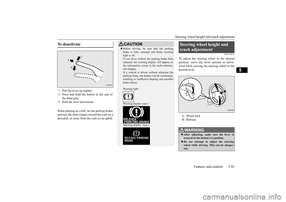
To adjust the steering wheel to the desiredposition, move the lever upward or down-ward while moving the steering wheel to the desired level.
To deactivate 1- Pull the lever up slightly. 2- Press and hold the button at the end of
the hand grip.
3- Push the lever downward.
CAUTION Before driving, be sure that the parking brake is fully released and brake warning light is off. If you drive without the parking brake fully released, the warning display will appear onthe information screen in the multi-informa- tion display. If a vehicle is driven without releasing theparking brake, the brakes will be overheated, resulting in ineffective braking and possible brake failure. Warning light Warning display type 1 Warning display type 2
Steering wheel height and reach adjustment A- Wheel lock B- ReleaseWA R N I N G After adjusting, make sure the lever is secured in the locked (A) position. Do not attempt to adjust the steering wheel while driving. This can be danger-ous.
BK0229600US.bo
ok 41 ページ 2015年10月1日 木曜日 午後2時29分
Page 104 of 398

Inside rearview mirror 5-42 Features and controls
5
N00511601369
Adjust the inside rear
view mirror only after
making any seat adjustme
nts so as to have a
clear view to the rear of the vehicle.
Adjust the inside mirror to maximize the view through the rear window. It is possible to move
the mirror up and down
to adjust its position.
It is possible to move the mirror up/down and left/right to adjust its position.
When releasing the lever (moving it to the position (B)), be sure to hold the steering wheel firmly. Otherwise, the steering wheel may slip down too suddenly.
Inside rearview mirror
WA R N I N G Do not attempt to adjust the inside rear- view mirror while driving. This can bedangerous. Be sure to adjust the mirror before driv- ing.WA R N I N G
To adjust the vertical mirror position Type 1 Type 2 Type 3
To adjust the mirror position
BK0229600US.bo
ok 42 ページ 2015年10月1日 木曜日 午後2時29分
Page 117 of 398
Continuously variable transmission (CVT) (if so equipped)
Features and controls 5-55
5
Move the lever to this position only after the vehicle has come to a complete stop. At this position, the transmission is disen- gaged. It is the same as the neutral position ona manual transaxle and
should be used when
the vehicle is not moving for an extended length of time during driving, such as in atraffic jam.
This position is used for most city and high- way driving. The transmission will automati- cally and continuously change its gear ratio depending on road and driving conditions.
N00560701078
Whether the vehicle is stationary or inmotion, sports mode is selected by pushingthe selector lever from the “D” (DRIVE) position into the manual gate (A). To return
to “D” (DRIVE) operation, push the selector lever back into the main gate (B). In sports mode, rapid sh
ifting is possible sim-
ply by operating the selector lever or spor-tronic steering wheel paddle shifter. Unlike the manual transaxle, sports mode allows shifting with the accelerator pedaldepressed.
“R” REVERSE
CAUTION Never shift into the “P” (PARK) or “R” (REVERSE) position while the vehicle is inmotion. If the lever is shifted into the “P” (PARK) or “R” (REVERSE) position while the vehicle is in motion, the transmissionmay be damaged.
“N” NEUTRAL
WA R N I N G Never move the selector lever to the “N” (NEUTRAL) position while driving since you could accidentally slip it into the “P”(PARK) or “R” (REVERSE) position, damaging the transmission.
To prevent the vehicle from rolling when stopped on a slope, the engine should be started in the “P” (PARK) position, not in “N” (NEUTRAL) position. To prevent rolling, always keep your foot on the brake pedal when the vehicle is in “N” (NEUTRAL) position, or when shift-ing into or out of “N” (NEUTRAL) posi- tion.
“D” DRIVE
CAUTION To prevent transmission damage, never shift into the “D” (DRIVE) position from the “R” (REVERSE) position while the vehicle is inmotion.
Sports mode
WA R N I N G
NOTE
For vehicles equipped with the sportronic steering wheel paddle shifter, sports mode can be operated even when the selector leveris in the main gate (B). Also, you can return to the “D” operation in any of following ways. When returning to “D” operation, theselector lever position display will change to “D” (DRIVE) position. • Pull the + (SHIFT UP) side sportronic steering wheel paddle shifter forward (toward the driver) for over 2 seconds. • Stop the vehicle • Push the selector lever from the “D” (DRIVE) position into the manual gate (A) and push the selector lever back into themain gate (B).
BK0229600US.bo
ok 55 ページ 2015年10月1日 木曜日 午後2時29分
Page 118 of 398
Continuously variable transmis
sion (CVT) (if so equipped)
5-56 Features and controls
5
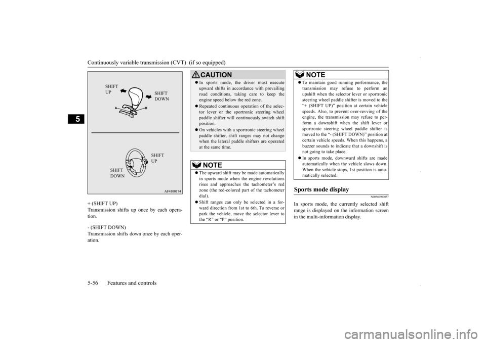
+ (SHIFT UP) Transmission shifts up once by each opera- tion. - (SHIFT DOWN) Transmission shifts down once by each oper-ation.
N00560900057
In sports mode, the currently selected shift range is displayed on the information screen in the multi-information display.
SHIFT UP
SHIFT DOWN SHIFT UP
SHIFT DOWN
CAUTION In sports mode, the driver must execute upward shifts in accordance with prevailing road conditions, taking care to keep the engine speed below the red zone. Repeated continuous operation of the selec- tor lever or the sportronic steering wheel paddle shifter will continuously switch shiftposition. On vehicles with a sportronic steering wheel paddle shifter, shift ranges may not change when the lateral paddle shifters are operated at the same time.NOTE
The upward shift may be made automatically in sports mode when the engine revolutions rises and approaches the tachometer’s redzone (the red-colored part of the tachometer dial). Shift ranges can only be selected in a for- ward direction from 1st to 6th. To reverse or park the vehicle, move the selector lever tothe “R” or “P” position.
To maintain good running performance, the transmission may refuse to perform an upshift when the selector lever or sportronic steering wheel paddle shifter is moved to the “+ (SHIFT UP)” position at certain vehiclespeeds. Also, to prevent over-revving of the engine, the transmission may refuse to per- form a downshift when the shift lever orsportronic steering wheel paddle shifter is moved to the “- (SHIFT DOWN)” position at certain vehicle speeds. When this happens, abuzzer sounds to indicate that a downshift is not going to take place. In sports mode, downward shifts are made automatically when the vehicle slows down. When the vehicle stops, 1st position is auto-matically selected.
Sports mode display
NOTE
BK0229600US.bo
ok 56 ページ 2015年10月1日 木曜日 午後2時29分
Page 123 of 398
4-wheel drive operation
Features and controls 5-61
5
When turning a sharp corner in “4WD LOCK” position at low speed, a slight differ- ence in steering may be experienced similarto feeling as if the brakes were applied. This
is called tight corner braking and results from each of the four tires being at a different dis- tance from the corner. The phenomenon is typical of 4-wheel drive vehicles. If thisoccurs, either straighten out the steering wheel or change to another mode. Set the drive mode-selector to “4WD AUTO” conditions, and then gradually depress the accelerator pedal for a smooth start.
WA R N I N G Do not over-rely on the 4-wheel drive vehi- cles. Even 4-wheel drive vehicles have lim- its to the system and ability to maintain control and traction. Reckless driving may lead to accidents. Always drive carefully,taking account of the road conditions. Improperly operating this vehicle on or off-pavement can cause an accident or rollover in which you and your passengers could be seriously injured or killed.• Follow all instructio
ns and guidelines in
the owner’s manual.• Keep your speed low and do not drivefaster than conditions.NOTE
Driving on rough roads can be hard on a vehicle. Before you leave the pavement, be sure all scheduled maintenance and servicehas been done, and that you have inspected your vehicle. Pay special attention to the condition of the tires, and check the tire pres-sures. Mitsubishi Motors is not responsible to the operator for any damage or injury caused or liability incurred by improper and negligentoperation of a vehicle. All techniques of vehicle operation depend on the skill and experience of the operator and other partici-pating parties. Any deviation from the rec- ommended operating instructions above is at their own risk.
Note that the stopping distance required of the 4-wheel drive vehicle differs very little from that of the front-wheel drive vehicle. When driving on a snow-covered road or a slippery, muddy surface, make sure that youkeep a sufficient distance between your vehi- cle and the one ahead of you. The driving posture should be more upright; adjust the seat to a good position for easy steering and pedal operation. Be sure to wearthe seat belt. After driving on rough roads, check each part of the vehicle and wash it thoroughly with water. Refer to the “Inspection and maintenance following rough road opera-tion” section and “Vehicle care and Mainte- nance” sections.CAUTION Setting the drive mode-selector to “4WD LOCK” position to drive on dry paved roadwill increase fuel consumption, with possible noise generation.
Turning sharp corners
NOTE
On snowy or icy roads
NOTE
The use of snow tires is recommended. Maintain a safe distance between vehicles, avoid sudden braking, and use engine brak- ing (downshifting).CAUTION Avoid sudden braking, sudden acceleration and sharp turning. Skidding occurs and con- trol of the vehicle could be lost.
BK0229600US.bo
ok 61 ページ 2015年10月1日 木曜日 午後2時29分
Page 129 of 398
Anti-lock braking system
Features and controls 5-67
5
N00517900240
The anti-lock braking system helps prevent the wheels from lockin
g up when braking.
This helps maintain vehicle drivability and steering wheel handling.
When using the anti-lock brakes (sudden braking), steering is slightly different from normal driving conditions. Use thesteering wheel carefully. Always keep a safe distance from the vehicle in front of you. Even if your vehi-cle is equipped with the anti-lock braking system, leave a greater braking distance when:• Driving on gravel or snow-coveredroads. • Driving on uneven road surfaces. Operation of anti-lock braking system is not restricted situations where brakes are applied suddenly. This system may also prevent the wheels from locking whenyou drive over manholes, steel roadwork plates, road markings, or any uneven road surface. When the anti-lock braking system is in use, you may feel the brake pedal vibrat- ing and hear a unique sound. It may alsofeel as if the pedal resists being pressed. In this situation, si
mply hold the brake
pedal down firmly. Do not pump thebrake, which will result in reduced braking performance.
N00531600645
Warning light
NOTE
Once the brake assist system is operational, it maintains great braking force even if the brake pedal is lightly released. To stop its operation, completely remove your foot from the brake pedal. When the brake assist system is in use while driving, you may feel as if the depressedbrake pedal is soft, the pedal moves in small motions in conjunction with the operation noise, or the vehicle body and the steeringwheel vibrate. This occurs when the brake assist system is operating normally and does not indicate faulty operation. Continue todepress the brake pedal. You may hear an operation noise when the brake pedal is suddenly or fully depressed while stationary. This does not indicate a malfunction and the brake assist system isoperating normally. When the anti-lock brake system warning light/display or only ASC warning display illuminate, the brake assist system in not functioning.
Anti-lock braking system
Driving hints
CAUTION The anti-lock braking system cannot prevent accidents. It is your responsibility to take safety precautions and to drive carefully. To prevent failure of the anti-lock braking system, be sure all 4 wheels and tires are the same size and the same type.NOTE
A whining sound is emitted from the engine compartment when driving immediately after starting the engine. These are the nor- mal sounds the anti-lock braking systemmakes when performing a self-check. It does not indicate a malfunction. The anti-lock braking system can be used after the vehicle has reached a speed over approximately 6 mph (10 km/h). It stopsworking when the vehicle slows below 3 mph (5 km/h).
Anti-lock braking system warn- ing light/display
BK0229600US.bo
ok 67 ページ 2015年10月1日 木曜日 午後2時29分