2016 MITSUBISHI OUTLANDER III instrument panel
[x] Cancel search: instrument panelPage 66 of 464

Supplemental Restraint System (SRS) - airbag 4-40 Seat and restraint systems
4
N00407901331
The driver’s airbag is located under the pad- ded cover in the middle of the steering wheel.The front passenger’s ai
rbag is contained in
the instrument panel above the glove com- partment. The driver’s airbag and the frontpassenger’s airbag are designed to deploy at the same time. However, the front passen- ger’s airbag does not deploy when the front passenger seat is not occupied or when the system senses that a child is in the childrestraint system.
N00404500010
The driver’s knee airbag is located under the steering wheel. The driver’s knee airbag is
designed to deploy at
the same time as the
driver’s front airbag.
Driver’s and passenger’s front airbag system Driver’s knee airbag system Driver
Front passenger
BK0223400US.book 40 ページ 2015年2月13日 金曜日 午後12時15分
Page 69 of 464
Supplemental Restraint System (SRS) - airbag
Seat and restraint systems 4-43
4
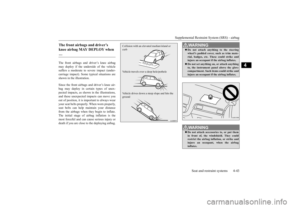
The front airbags and driver’s knee airbag may deploy if the underside of the vehiclesuffers a moderate to
severe impact (under-
carriage impact). Some typical situations are shown in the illustration. Since the front airbags and driver’s knee air- bag may deploy in ce
rtain types of unex-
pected impacts, as show
n in the illustrations,
and these unexpected impacts can move you out of position, it is
important to always wear
your seat belts properly. When worn properly,seat belts can help maintain your distance from the airbags when they begin to inflate. The initial stage of airbag inflation is themost forceful and can cause serious injury or death if you are close to the deploying airbag.The front airbags and driver’s knee airbag MAY DEPLOY when …
Collision with an elevat
ed median/island or
curb Vehicle travels over a deep hole/pothole Vehicle drives down a steep slope and hits the ground
WA R N I N G Do not attach anything to the steering wheel’s padded cover, such as trim mate-rial, badges, etc. These could strike andinjure an occupant if
the airbag inflates.
Do not set anything on, or attach anything to, the instrument
panel above the glove
compartment. Such items could strike and injure an occupant if
the airbag inflates.
WA R N I N GDo not attach accessories to, or put them in front of, the wind
shield. They could
restrict the airbag infl
ation, or strike and
injure an occupant, when the airbag inflates.
BK0223400US.book 43 ページ 2015年2月13日 金曜日 午後12時15分
Page 70 of 464

Supplemental Restraint System (SRS) - airbag 4-44 Seat and restraint systems
4
N00408101431
The side airbags (A) are contained in the driver and front passenger seatbacks. The side airbag is de
signed to inflate only on
the side of the vehicle that is impacted, even with no passenger in the front seat. A label is attached to the seatbacks in vehi- cles equipped with side airbags.
Do not attach addition
al keys or accesso-
ries (hard, pointed or
heavy objects) to the
ignition key. Such objects could preventthe driver’s knee ai
rbag from inflation
normally or could be propelled to cause serious injury if
the airbag inflates.
Do not attach accessories to the lower por- tion of the driver’s side instrument panel.Such objects could prevent the driver’s knee airbag from inflating normally or could be propelled to cause serious injuryif the airbag inflates.WA R N I N G Do not attempt to remove, install, disas- semble or repair the SRS airbags.WA R N I N G
Do not place objects,
such as packages or
pets, between the airbags and the driveror the front passenger. Such objects canadversely affect ai
rbag performance, or
cause serious injury or death when the airbag deploys. Immediately after airbag inflation, some parts of the airbag syst
em will be hot. Do
not touch them. You could otherwise be burned. The airbag system is designed to work only once. After the
airbags deploy, they
will not work again. They must promptlybe replaced and the
entire airbag system
must be inspected by
an authorized Mit-
subishi Motors dealer.WA R N I N G
Side airbag system
BK0223400US.book 44 ページ 2015年2月13日 金曜日 午後12時15分
Page 75 of 464
Supplemental Restraint System (SRS) - airbag
Seat and restraint systems 4-49
4
N00408500669
SRS servicing
WA R N I N G Any maintenance performed on or near the components of the SRS should be per-formed only by an
authorized Mitsubishi
Motors dealer. Do not permit anyone else to do any service, inspection, maintenanceor repair on any SR
S components or wir-
ing. Similarly, no part of the SRS should ever be handled, removed or disposed byanyone except an au
thorized Mitsubishi
Motors dealer. Improper work meth
ods on the SRS com-
ponents or wiring could result in an acci- dental airbag deployment or could make the SRS inoperable. Ei
ther of these situa-
tions could result in serious injury or death. Do not modify your steering wheel or any other SRS component or related vehicle part. For example, replacement of thesteering wheel, or modifications to the front bumper or body structure can adversely affect SR
S performance and
may lead to injury. If your vehicle has
received any damage,
you should have the
SRS inspected by an
authorized Mitsubishi
Motors dealer to
make sure it is in
proper work
ing order.
Do not modify your front seats, center pil- lar or center console. Such modificationscan adversely affect
SRS performance and
may lead to injury. Also, if you discove
r any tear or open
seam in the seat fabr
ic near the side air-
bag, have the seat in
spected by an autho-
rized Mitsubishi Motors dealer. If you have found an
y scratch, crack or
damage to the portion of the front and rear pillars and roof
side rail, you should
have the SRS inspected by an authorized Mitsubishi Motors dealer.NOTE
When you transfer ownership of the vehicle to another person, we
urge you to alert the
new owner that it is
equipped with the SRS
and refer that owner to the applicable sec- tions in this owner’s manual. If you decide to junk or scrap your vehicle, we urge you to first take it to an authorized Mitsubishi Motors dealer so that the SRS canbe made safe for disposal. If any of the following parts needs to be modified for use by a handicapped person,the advanced airbag sy
stem will be greatly
affected. Please consult an authorized Mit- subishi Motors dealer. • Driver’s seat • Front passenger seat • Front seat beltWA R N I N G
• Steering wheel • Instrument panel[For vehicles so
ld in U.S.A.]
To contact Mitsubi
shi Motors North
America, Inc. call 1-888-648-7820 or write to: Mitsubishi Motors North America, Inc.Customer Relations Department P.O. Box 6400 Cypress, CA 90630-0064 [For vehicles so
ld in Canada]
To contact Mitsubishi Motor Sales ofCanada, Inc. call 1-888-576-4878 or write to: Mitsubishi Motor Sales of Canada, Inc.Customer Relations Department P.O. Box 41009 4141 Dixie RoadMississauga, ON L4W 5C9NOTE
BK0223400US.book 49 ページ 2015年2月13日 金曜日 午後12時15分
Page 91 of 464
Free-hand Advanced Securi
ty Transmitter (F.A.S.T.-key) (if so equipped)
Features and controls 5-15
5
N00503301077
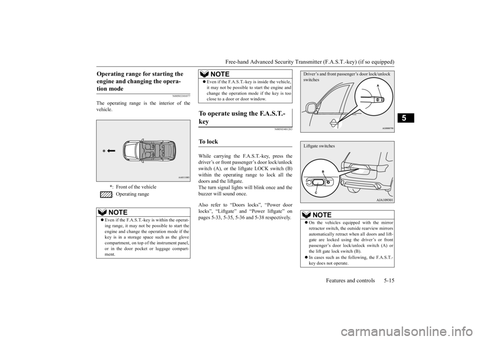
The operating range is the interior of the vehicle.
N00503401283
While carrying the F.A.S.T.-key, press thedriver’s or front passenger’s door lock/unlock switch (A), or the liftgate LOCK switch (B) within the operating range to lock all thedoors and the liftgate. The turn signal lights will blink once and the buzzer will sound once. Also refer to “Doors locks”, “Power door locks”, “Liftgate” and “Power liftgate” on pages 5-33, 5-35, 5-36 and 5-38 respectively.
Operating range for starting the engine and changing the opera-tion mode
* : Front of the vehicle : Operating range
NOTE
Even if the F.A.S.T.-key is within the operat- ing range, it may not be possible to start theengine and change the
operation mode if the
key is in a storage space such as the glove compartment, on top of the instrument panel,or in the door pocket or luggage compart- ment.
Even if the F.A.S.T.-key is inside the vehicle, it may not be possible to
start the engine and
change the operation mode if the key is tooclose to a door or door window.
To operate using the F.A.S.T.- key
To l o c k
NOTE
NOTE
On the vehicles equipped with the mirror retractor switch, the outside rearview mirrorsautomatically retract when all doors and lift- gate are locked using the driver’s or front passenger’s door lock/unlock switch (A) orthe lift gate lock switch (B). In cases such as the following, the F.A.S.T.- key does not operate.Driver’s and front passenger’s door lock/unlock switchesLiftgate switches
BK0223400US.book 15 ページ 2015年2月13日 金曜日 午後12時15分
Page 102 of 464
Free-hand Advanced
Security Transmitter (F.A.S
.T.-key) (if so equipped)
5-26 Features and controls
5
1. Stop the vehicle. 2. Fully engage the parking brake while depressing the brake pedal. 3. Move the selector
lever to the “P”
(PARK) position, and then press the engine switch to stop the engine.
N00568301041
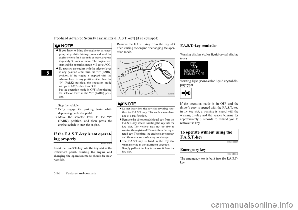
Insert the F.A.S.T.-key into the key slot in the instrument panel. St
arting the engine and
changing the operation mode should be now possible.
Remove the F.A.S.T.-key from the key slot after starting the engine
or changing the oper-
ation mode.
Warning display (color liquid crystal display type) Warning light (mono-color liquid crystal dis- play type) If the operation mode is in OFF and the driver’s door is opened with the F.A.S.T.-key in the key slot, a warni
ng is issued with the
warning display and
the buzzer buzzing for
approximately 3 seconds to remind you to remove the key.
N00514800017 N00515201158
The emergency key is built into the F.A.S.T.- key.
NOTE
If you have to bring the engine to an emer- gency stop while driving, press and hold theengine switch for 3 seconds or more, or pressit quickly 3 times or
more. The engine will
stop and the operation m
ode will go to ACC.
Do not stop the engine wi
th the selector lever
in any position other than the “P” (PARK) position. If the engine is stopped with theselector lever in any
position other than the
“P” (PARK) position, the operation mode will go to ACC rather than OFF.Put the operation mode
in OFF after placing
the selector lever in the “P” (PARK) posi- tion.
If the F.A.S.T.-key is not operat- ing properly
NOTE
Do not insert into the
key slot anything other
than the F.A.S.T.-key. This could cause dam- age or a malfunction. Remove the object or additional key from the F.A.S.T.-key before inserting the key into the key slot. The vehicle
may not be able to
receive the registered ID code from the regis- tered key. Therefore, th
e engine may not start
and the operation mode may not change. The F.A.S.T.-key is fixed in the key slot when inserted in the illustrated direction.Simply pull out the key to remove it from the key slot.
F.A.S.T.-key reminder
To operate without using the F. A . S . T. - k e y
Emergency key
BK0223400US.book 26 ページ 2015年2月13日 金曜日 午後12時15分
Page 254 of 464
Combination headlights and dimmer switch 5-178 Features and controls
5
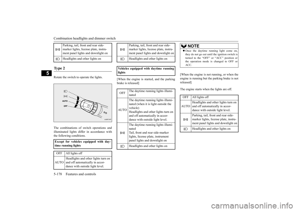
Rotate the switch to operate the lights. The combinations of
switch operations and
illuminated lights differ in accordance with the following conditions.
[When the engine is started, and the parking brake is released]
[When the engine is not running, or when the engine is running but the parking brake is not released] The engine starts when the lights are off.
Parking, tail, front and rear side- marker lights, license plate, instru- ment panel lights and downlight on Headlights and
other lights on
Ty p e 2 Except for vehicles equipped with day- time running lights OFF All lights off AUTO
Headlights and other lights turn on and off automatically in accor- dance with outside light level.
Parking, tail, front
and rear side-
marker lights, license plate, instru- ment panel lights
and downlight on
Headlights and other lights on
Vehicles equipped
with daytime running
lights OFF
The daytime runni
ng lights illumi-
nated
AUTO
The daytime runni
ng lights illumi-
nated (when it is light outside the vehicle) Headlights and other lights turn on and off automatically in accor-dance with outside light level. The daytime runni
ng lights illumi-
natedTail, front and rear side-marker lights, license pl
ate, instrument
panel lights and downlight on Headlights and other lights on
NOTE
Once the daytime running light come on, they do not go out until the ignition switch isturned to the “OFF” or “ACC” position orthe operation mode is changed to OFF or ACC.OFF All lights off AUTO
Headlights and other lights turn on and off automatically in accor- dance with outside light level. Parking, tail, front
and rear side-
marker lights, license plate, instru-ment panel lights and downlight on Headlights and other lights on
BK0223400US.book 178 ページ 2015年2月13日 金曜日 午後12時15分
Page 257 of 464
Combination headlights and dimmer switch
Features and controls 5-181
5
N00550001209
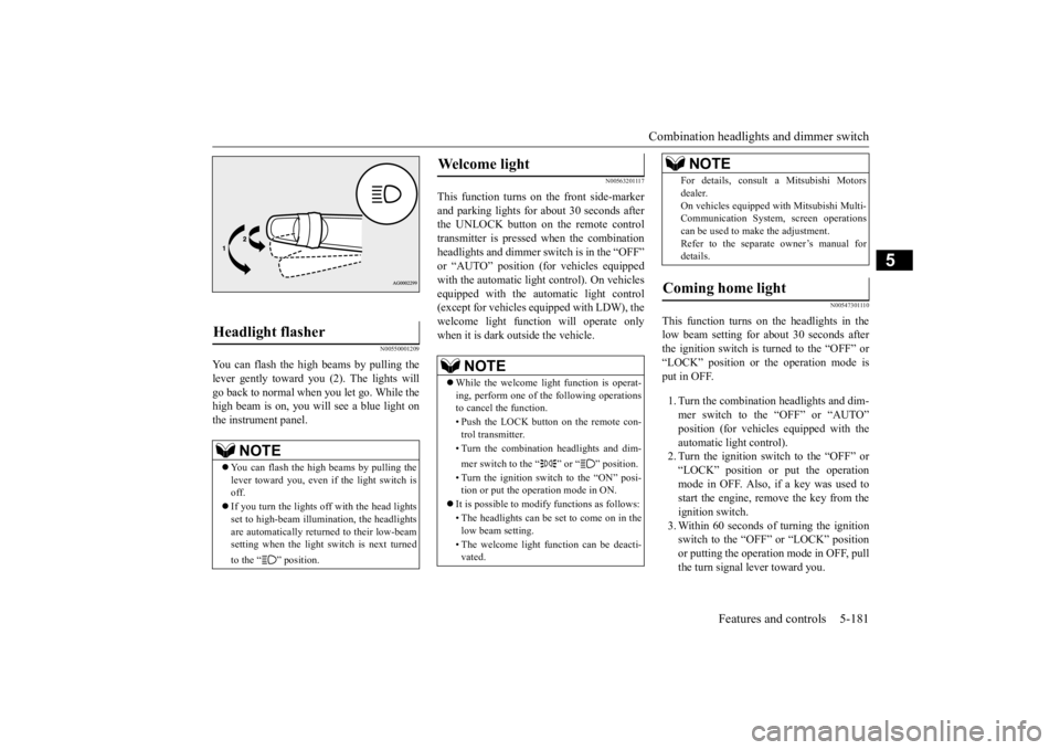
You can flash the high beams by pulling the lever gently toward you (2). The lights will go back to normal when you let go. While the high beam is on, you will see a blue light onthe instrument panel.
N00563201117
This function turns on the front side-marker and parking lights for about 30 seconds after the UNLOCK button on the remote controltransmitter is pressed when the combination headlights and dimmer swit
ch is in the “OFF”
or “AUTO” position (fo
r vehicles equipped
with the automatic light control). On vehicles equipped with the automatic light control (except for vehicles equipped with LDW), the welcome light functi
on will operate only
when it is dark outside the vehicle.
N00547301110
This function turns on the headlights in thelow beam setting for about 30 seconds afterthe ignition switch is turned to the “OFF” or “LOCK” position or the operation mode is put in OFF. 1. Turn the combination headlights and dim- mer switch to the “OFF” or “AUTO” position (for vehicles
equipped with the
automatic light control).2. Turn the ignition switch to the “OFF” or “LOCK” position or put the operation mode in OFF. Also, if a key was used tostart the engine, rem
ove the key from the
ignition switch. 3. Within 60 seconds of turning the ignitionswitch to the “OFF” or “LOCK” position or putting the operation mode in OFF, pull the turn signal lever toward you.
Headlight flasher
NOTE
You can flash the high beams by pulling the lever toward you, even if the light switch is off. If you turn the lights off with the head lights set to high-beam illumi
nation, the headlights
are automatically returned to their low-beamsetting when the light
switch is next turned
to the “ ” position.
Welcome light
NOTE
While the welcome light function is operat- ing, perform one of
the following operations
to cancel the function. • Push the LOCK button on the remote con- trol transmitter. • Turn the combination headlights and dim- mer switch to the “ ” or “ ” position. • Turn the ignition switch to the “ON” posi- tion or put the operation mode in ON.
It is possible to modify functions as follows: • The headlights can be set to come on in the low beam setting. • The welcome light f
unction can be deacti-
vated.
For details, consult a Mitsubishi Motorsdealer.On vehicles equipped
with Mitsubishi Multi-
Communication System
, screen operations
can be used to make the adjustment. Refer to the separate owner’s manual fordetails.
Coming home light
NOTE
BK0223400US.book 181 ページ 2015年2月13日 金曜日 午後12時15分