2016 MERCEDES-BENZ SL-CLASS ROADSTER clock
[x] Cancel search: clockPage 490 of 614
XRemove discharged batteriesA from th e
tray.
XInser tth ene wbatteries. Observ eth epolar -
it y marking son th ebatterie sand battery
compartmen twhen doin gso.
Left-han dbattery: th epositive pole (+)
mus tfac eupwards.
Right-hand battery: th epositive pole (+)
mus tfac edownwards.
XTo close th ebatter ycompartment :
inser tbattery compartmen tcover =start -
in g wit hretainin glugs ?into th ebattery
compartmen tand allow catch tab ;to
engage in place.
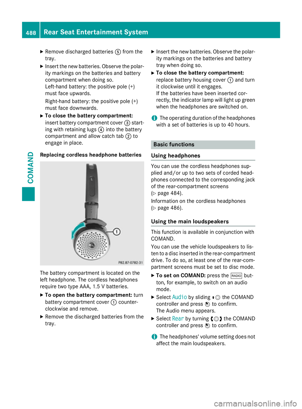
Replacing cordless headphon ebatteries
The battery compartmen tis locate don th e
lef theadphone .The cordless headphone s
require tw otyp eAAA, 1. 5 Vbatteries.
XTo ope nth ebatter ycompartment :tur n
battery compartmen tcover :counter-
clockwise and remove .
XRemove thedischarged batterie sfrom th e
tray.
XInser tth ene wbatteries. Observ eth epolar -
it y marking son th ebatterie sand battery
tray when doin gso.
XTo close th ebatter ycompartment :
replace battery housin gcover :and tur n
it clockwise until it engages.
If th ebatterie shav ebeen inserte dcor-
rectly, th eindicato rlamp will ligh tup green
when th eheadphone sare switched on .
iThe operating duration of th eheadphone s
wit h a set of batterie sis up to 40 hours.
Basic functions
Usin gheadphones
You can use th ecordless headphone ssup-
plied and/o rup to tw oset sof corde dhead -
phone sconnecte dto th ecorrespondin gjac k
of th erear-compartmen tscreens
(
Ypage 484).
Information on th ecordless headphone s
(
Ypage 486).
Usin gth emain loudspeaker s
This function is available in conjunction wit h
COMAND .
You can use th evehicl eloudspeakers to lis-
te nto adisc inserte din th erear-compartmen t
drive. To do so, at least on eof th erear-com-
partmen tscreens mus tbe set to disc mode.
XTo set on COMAND: press the$ but-
ton, for example, to switch on an audio
mode.
XSelec tAudioby slidin gZV theCOMAND
controller and press Wto confirm .
The Audio men uappears.
XSelec tRea rby turning cVdtheCOMAND
controller and press Wto confirm .
iThe headphones' volume setting does no t
affec tth emain loudspeakers .
488Rear Seat Entertainment System
COMAND
Page 540 of 614
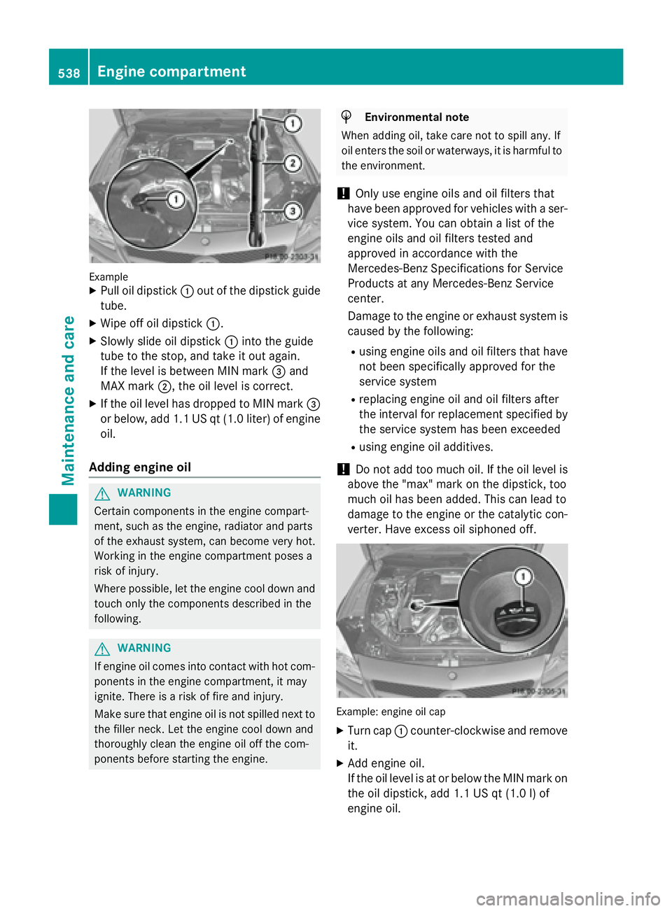
ExampleXPull oil dipstick:out of the dipstick guide
tube.
XWipe off oil dipstick :.
XSlowly slide oil dipstick :into the guide
tube to the stop, and take it out again.
If the level is between MIN mark =and
MAX mark ;, the oil level is correct.
XIf the oil level has dropped to MIN mark =
or below, add 1.1 US qt (1.0 liter) of engine
oil.
Adding engine oil
GWARNING
Certain components in the engine compart-
ment, such as the engine, radiator and parts
of the exhaust system, can become very hot.
Working in the engine compartment poses a
risk of injury.
Where possible, let the engine cool down and touch only the components described in the
following.
GWARNING
If engine oil comes into contact with hot com- ponents in the engine compartment, it may
ignite. There is a risk of fire and injury.
Make sure that engine oil is not spilled next to
the filler neck. Let the engine cool down and
thoroughly clean the engine oil off the com-
ponents before starting the engine.
HEnvironmental note
When adding oil, take care not to spill any. If
oil enters the soil or waterways, it is harmful to
the environment.
!Only use engine oils and oil filters that
have been approved for vehicles with a ser-
vice system. You can obtain a list of the
engine oils and oil filters tested and
approved in accordance with the
Mercedes-Benz Specifications for Service
Products at any Mercedes-Benz Service
center.
Damage to the engine or exhaust system is
caused by the following:
Rusing engine oils and oil filters that have
not been specifically approved for the
service system
Rreplacing engine oil and oil filters after
the interval for replacement specified by the service system has been exceeded
Rusing engine oil additives.
!Do not add too much oil. If the oil level is
above the "max" mark on the dipstick, too
much oil has been added. This can lead to
damage to the engine or the catalytic con-
verter. Have excess oil siphoned off.
Example: engine oil cap
XTurn cap :counter-clockwise and remove
it.
XAdd engine oil.
If the oil level is at or below the MIN mark on
the oil dipstick, add 1.1 US qt (1.0 l)of
engine oil.
538Engine compartment
Maintenance and care
Page 541 of 614
XReplacecap :on th efiller neck and tur n
clockwise .
Ensur ethat th ecap locks into plac e
securely.
XChec kth eoil level again wit hth eoil dip-
stick (
Ypage 537).
Further information on engin eoil
(
Ypage 605).
Checking and addin gother service
products
Checking coolant level
GWARNIN G
Certain component sin th eengin ecompart-
ment, suc has th eengine, radiato rand part s
of th eexhaust system, can become ver yhot .
Working in th eengin ecompartmen tposes a
ris kof injury.
Where possible, let th eengin ecool down and
touch only th ecomponent sdescribed in th e
following.
GWARNIN G
The engin ecoolin gsystem is pressurized, par-
ticularly when th eengin eis warm .Whe n
openin gth ecap ,you could be scalded by hot
coolan tsprayin gout .There is aris kof injury.
Let th eengin ecool down before openin gth e
cap .Wear eye and han dprotection when
openin gth ecap .Ope nth ecap slowly half a
tur nto allow pressur eto escape.
Exampl e
XPark thevehicl eon alevel surface.
Only chec kth ecoolan tlevel when th evehi-
cle is on alevel surfac eand th eengin ehas
cooled down .
XTurn theSmartKey to position 2in th eigni-
tion loc k (
Ypage 151).
On vehicles wit hKEYLESS-GO ,press th e
Start/Sto pbutto ntwice (
Ypage 152).
XCheckth ecoolan ttemperature gauge in
th emultifunction display.
The coolan ttemperature mus tbe belo w
15 8 ‡ (70 †).
XTurn th eSmartKey to position
0 (
Ypage 151) in th eignition lock.
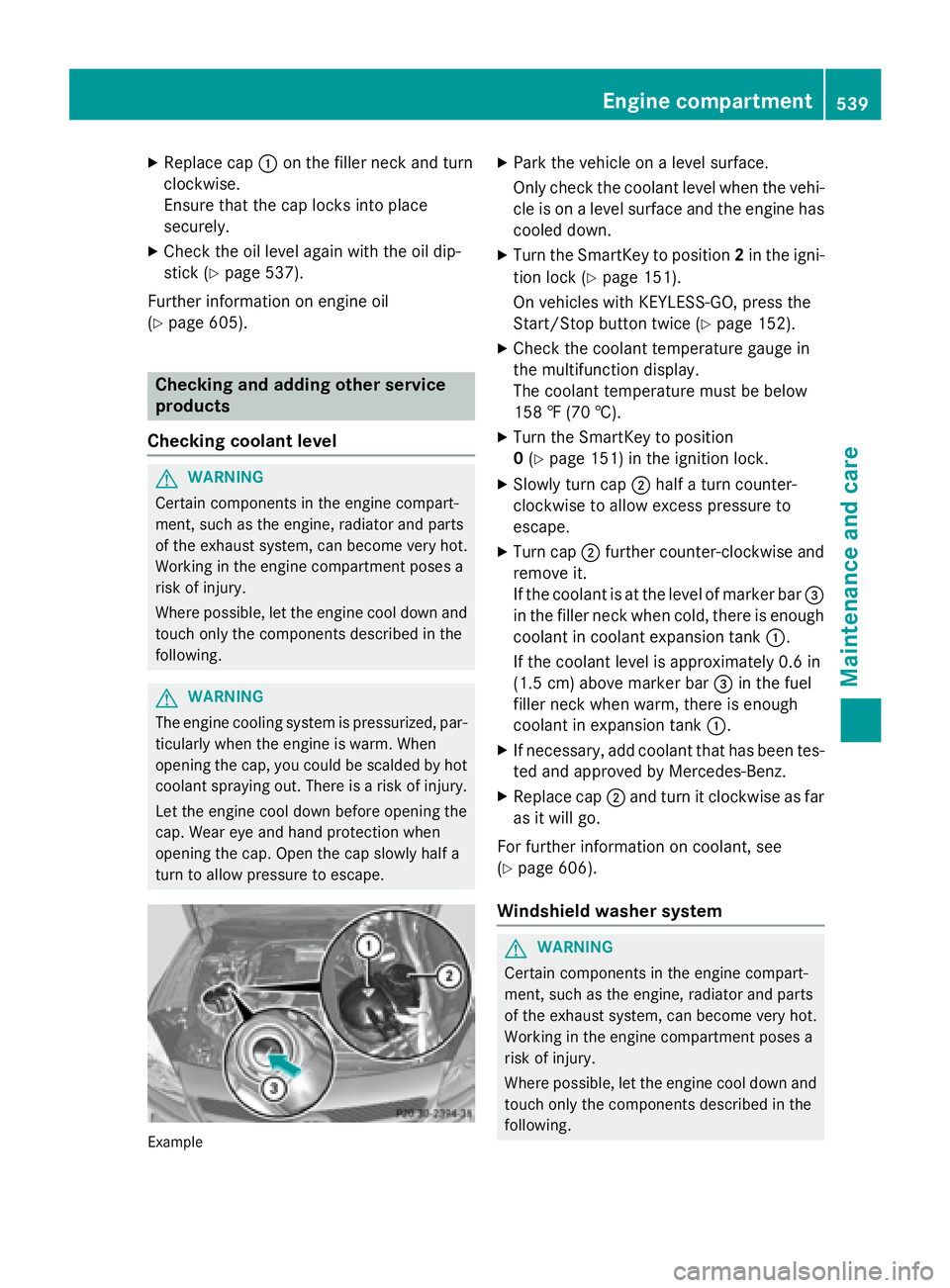
XSlowly tur ncap ;half atur ncounter-
clockwise to allow excess pressur eto
escape.
XTurn cap ;further counter-clockwise and
remove it .
If th ecoolan tis at th elevel of marke rbar =
in th efiller neck when cold, there is enough
coolan tin coolan texpansion tan k:.
If th ecoolan tlevel is approximately 0. 6in
(1.5 cm ) above marker bar =in the fuel
filler neck when warm, there is enough
coolant in expansion tank :.
XIf necessary, add coolant that has been tes-
ted and approved by Mercedes-Benz.
XReplace cap;and turn it clockwise as far
as it will go.
For further information on coolant, see
(
Ypage 606).
Windshield washer system
GWARNING
Certain components in the engine compart-
ment, such as the engine, radiator and parts
of the exhaust system, can become very hot.
Working in the engine compartment poses a
risk of injury.
Where possible, let the engine cool downand
touch only the components describe d in the
foll owin g.
Engine compartment539
Maintenance and care
Z
Page 559 of 614
The battery and the cover of the positive
terminal clamp must be installed securely
during operation.
In order for the battery to achieve the maxi-
mum possible service life, it must always be
sufficiently charged.
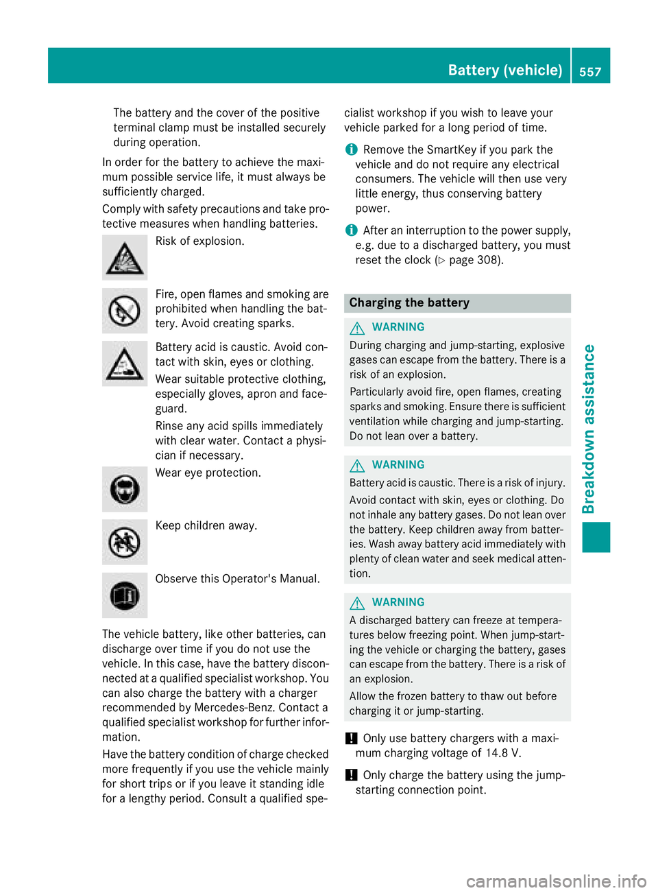
Comply with safety precautions and take pro-
tective measures when handling batteries.
Risk of explosion.
Fire, open flames and smoking are
prohibited when handling the bat-
tery. Avoid creating sparks.
Battery acid is caustic. Avoid con-
tact with skin, eyes or clothing.
Wear suitable protective clothing,
especially gloves, apron and face-
guard.
Rinse any acid spills immediately
with clear water. Contact a physi-
cian if necessary.
Wear eye protection.
Keep children away.
Observe this Operator's Manual.
The vehicle battery, like other batteries, can
discharge over time if you do not use the
vehicle. In this case, have the battery discon-
nected at a qualified specialist workshop. You
can also charge the battery with a charger
recommended by Mercedes-Benz. Contact a
qualified specialist workshop for further infor-
mation.
Have the battery condition of charge checked
more frequently if you use the vehicle mainly
for short trips or if you leave it standing idle
for a lengthy period. Consult a qualified spe- cialist workshop if you wish to leave your
vehicle parked for a long period of time.
iRemove the SmartKey if you park the
vehicle and do not require any electrical
consumers. The vehicle will then use very
little energy, thus conserving battery
power.
iAfter an interruption to the power supply,
e.g. due to a discharged battery, you must
reset the clock (
Ypage 308).
Charging the battery
GWARNING
During charging and jump-starting, explosive
gases can escape from the battery. There is a risk of an explosion.
Particularly avoid fire, open flames, creating
sparks and smoking. Ensure there is sufficient
ventilation while charging and jump-starting.
Do not lean over a battery.
GWARNING
Battery acid is caustic. There is a risk of injury.
Avoid contact with skin, eyes or clothing. Do
not inhale any battery gases. Do not lean over
the battery. Keep children away from batter-
ies. Wash away battery acid immediately with
plenty of clean water and seek medical atten-
tion.
GWARNING
A discharged battery can freeze at tempera-
tures below freezing point. When jump-start-
ing the vehicle or charging the battery, gases can escape from the battery. There is a risk of
an explosion.
Allow the frozen battery to thaw out before
charging it or jump-starting.
!Only use battery chargers with a maxi-
mum charging voltage of 14.8 V.
!Only charge the battery using the jump-
starting connection point.
Battery (vehicle)557
Breakdown assistance
Z
Page 563 of 614
Position numberBidentifies the charged battery of the other vehicle or an equivalent jump-
starting device.
XPress cover :of positive terminal ;down (in the direction of the arrow) and turn it
clockwise. Cover :is held down in the lowered position, which exposes positive termi-
nal ;.
XConnect positive terminal ;on your vehicle to positive terminal =of donor battery B
using the jumper cable, always begin with positive terminal ;on your own vehicle first.
XStart the engine of the donor vehicle and run it at idling speed.
XConnect negative terminal ?of donor battery Bto ground point Aof your vehicle using
the jumper cable, connecting the jumper cable to battery of other vehicle Bfirst.
XStart the engine.
XBefore disconnecting the jumper cables, let the engine run for several minutes.
XFirst, remove the jumper cables from ground point Aand negative terminal ?, then from
positive clamp ;and positive terminal =. Begin each time at the contacts on your own
vehicle first.
XAfter removing the jumper cables, press down cover :of positive terminal ;and turn it
counter-clockwise. Cover :returns to its original position. Positive terminal ;is covered
up and thus insulated again.
XHave the battery checked at a qualified specialist workshop.
Jump-starting is not considered to be a normal operating condition.
iJumper cables and further information regarding jump-starting can be obtained at any
qualified specialist workshop.
Towing and tow-starting
Important safety notes
GWARNING
When towing or tow-starting another vehicle
and its weight is greater than the permissible
gross weight of your vehicle, the:
Rthe towing eye could detach itself
Rthe vehicle/trailer combination could roll-
over.
There is a risk of an accident.
When towing or tow-starting another vehicle,
its weight should not be greater than the per- missible gross weight of your vehicle.
!Only secure the tow rope or tow bar at the
towing eyes. Otherwise, the vehicle could
be damaged.
!If DISTRONIC PLUS or the HOLD function
is activated, the vehicle brakes automati-
cally in certain situations.
To prevent damage to the vehicle, deacti-
vate DISTRONIC PLUS and the HOLD func-
tion in the following or other similar situa-
tions:
Rwhen towing the vehicle
Rin the car wash
!Do not use the towing eye for recovery,
this could damage the vehicle. If in doubt,
recover the vehicle with a crane.
!When towing, pull away slowly and
smoothly. If the tractive power is too high,
the vehicles could be damaged.
!Do not tow with sling-type equipment.
This could damage the vehicle.
Towing and tow-starting561
Breakdown assistance
Z
Page 564 of 614
!When towing vehicles with KEYLESS-GO,
use the key instead of the Start/Stop but-
ton. Otherwise, the automatic transmission
may shift to position Pwhen the driver's or
front-passenger door are opened, which
could lead to damage to the transmission.
!Make sure that the electric parking brake
is released. If the electric parking brake is
faulty, visit a qualified specialist workshop.
!The vehicle can be towed a maximum of
30 miles (50km). The towing speed of
30 mph (50 km/h) must not be exceeded.
If the vehicle has to be towed more than
30 miles (50km), the entire vehicle must be
raised and transported.
!If you tow or tow-start another vehicle, its
weight must not exceed the maximum per-
missible gross vehicle weight of your vehi-
cle.
iInformation on your vehicle's gross vehi-
cle weight rating can be found on the vehi-
cle identification plate; see the printed
Operator's Manual.
iInformation on your vehicle's gross vehi-
cle weight rating can be found on the vehi-
cle identification plate (
Ypage 601).
It is better to have the vehicle transported
than to have it towed away.
The automatic transmission must be in posi-
tion Nwhen the vehicle is being towed.
The battery must be connected and charged. Otherwise, you:
Rcannot turn the SmartKey to position 2in
the ignition lock
Rcannot shift the automatic transmission to position N.
Before the vehicle is towed, deactivate the
automatic locking feature (
Ypage 234). You
could otherwise be locked out when pushing
or towing the vehicle.
Installing/removing the towing eye
Installing the towing eye
GWARNING
The exhaust tail pipe may be very hot. There is
a risk of burns when removing the rear cover.
Do not touch the exhaust pipe. Take particular
care when removing the rear cover.
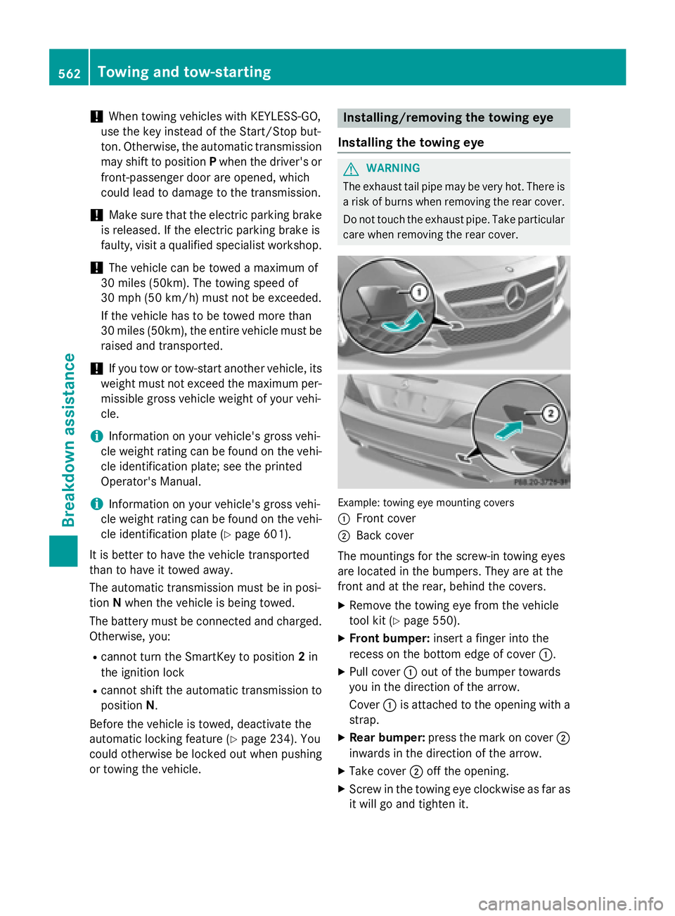
Example: towing eye mounting covers
:
Front cover
;Back cover
The mountings for the screw-in towing eyes
are located in the bumpers. They are at the
front and at the rear, behind the covers.
XRemove the towing eye from the vehicle
tool kit (
Ypage 550).
XFront bumper: insert a finger into the
recess on the bottom edge of cover :.
XPull cover:out of the bumper towards
you in the direction of the arrow.
Cover :is attached to the opening with a
strap.
XRear bumper: press the mark on cover ;
inwards in the direction of the arrow.
XTake cover ;off the opening.
XScrew in the towing eye clockwise as far as
it will go and tighten it.
562Towing and tow-starting
Breakdown assistance
Page 594 of 614
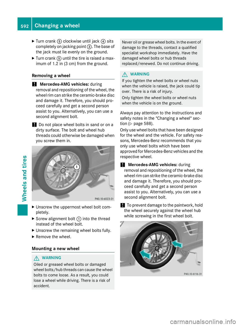
XTurn crankAclockwise until jack ?sits
completely on jacking point =. The base of
the jack must lie evenly on the ground.
XTurn crank Auntil the tire is raised a max-
imum of 1.2 in (3 cm) from the ground.
Removing a wheel
!Mercedes-AMG vehicles: during
removal and repositioning of the wheel, the
wheel rim can strike the ceramic-brake disc
and damage it. Therefore, you should pro-
ceed carefully and get a second person
assist to you. Alternatively, you can use a
second alignment bolt.
!Do not place wheel bolts in sand or on a
dirty surface. The bolt and wheel hub
threads could otherwise be damaged when
you screw them in.
XUnscrew the uppermost wheel bolt com-
pletely.
XScrew alignment bolt :into the thread
instead of the wheel bolt.
XUnscrew the remaining wheel bolts fully.
XRemove the wheel.
Mounting a new wheel
GWARNING
Oiled or greased wheel bolts or damaged
wheel bolts/hub threads can cause the wheel bolts to come loose. As a result, you could
lose a wheel while driving. There is a risk of
accident.
Never oil or grease wheel bolts. In the event of
damage to the threads, contact a qualified
specialist workshop immediately. Have the
damaged wheel bolts or hub threads
replaced/renewed. Do not continue driving.
GWARNING
If you tighten the wheel bolts or wheel nuts
when the vehicle is raised, the jack could tip
over. There is a risk of injury.
Only tighten the wheel bolts or wheel nuts
when the vehicle is on the ground.
Always pay attention to the instructions and
safety notes in the "Changing a wheel" sec-
tion (
Ypage 588).
Only use wheel bolts that have been designed for the wheel and the vehicle. For safety rea-
sons, Mercedes-Benz recommends that you
only use wheel bolts which have been
approved for Mercedes-Benz vehicles and the
respective wheel.
!Mercedes-AMG vehicles: during
removal and repositioning of the wheel, the
wheel rim can strike the ceramic-brake disc
and damage it. Therefore, you should pro-
ceed carefully and get a second person
assist to you. Alternatively, you can use a
second alignment bolt.
!To prevent damage to the paintwork, hold
the wheel securely against the wheel hub
while screwing in the first wheel bolt.
592Changing a wheel
Wheels and tires
Page 595 of 614

XClean the wheel and wheel hub contact
surfaces.
XSlidethe wheel to be mounted onto the
alignment bolt and push iton.
XTighten the wheel bolts until they are fin-
ger-tight.
XUnscrew the alignment bolt.
XTighten the last wheel bolt until itis finger-
tight.
Lowering the vehicle
GWARNIN G
The wheels could work loos eif th ewhee lnut s
and bolt sare no ttightened to th especifie d
tightening torque .Ther eis aris kof accident.
Hav eth etightening torque immediately
checked at aqualified specialist worksho p
after awhee lis changed.
XTurn the crank of the jack counter-clock-
wise untilthe vehicle isonce again standing
firmly on the ground.
XPlace the jack to one side.
XTighten the wheel bolts evenly ina cross-
wise pattern inthe sequence indicated ( :
to A). The specified tightening torque is
96 lb-ft (130 Nm).
XTurn the jack back to its initial position.
XSt ow the jack and the rest of the vehicle
tools inthe trunk again.
XMercedes-AMG vehicles and vehicles
with AMG equipment: insert the cover
into the outer sill.
XCheck the tire pressure of the newly moun-
ted wheel and adjust it ifnecessary.
Observe the recommended tire pressure
(
Ypage 571).
iWhen you are drivingwith the emergency
spare wheel mounte d,the tire pressure
mon itor cannot function reliably. Only
restart the tire pressure monitor when the
defect ivewheel has been replaced with a
new wheel.
All mounted wheels must be equippedwith
functioning sensors for the tire pressure
mon itor.
Wheel and tire combinations
General notes
!
For safety reasons, Mercedes-Benz rec-
ommends that you only use tires and
wheels which have been approved by
Mercedes-Benz specific ally for your vehi-
cle.
These tires have been specially adapted for
use with the control systems, such as ABS
or ESP
®, and are marked as follows:
RMO = Mercedes-Benz Original
RMOE = Mercedes-Benz Original Extended
(t ires featuring run-flat characteristics)
RMO1 = Mercedes-Benz Original (only cer-
tain AMG tires)
Mercedes-Benz Original Extended tires
may only be used on wheels that have been
specifically approved byMercedes-Benz.
Only use tires, wheels or accessories tes-
ted and approved byMercedes-Benz. Cer-
tain characteristics, e.g. handlin g, vehicle
noise emissions or fuel consumption, may
otherwise beadverse lyaffected. Inaddi-
tion, when driving with a load, tire dimen-
sion variations could cause the tires to
come into contact with the bodywork and
Wheel and tire combinations593
Wheels and tires
Z