Page 395 of 438

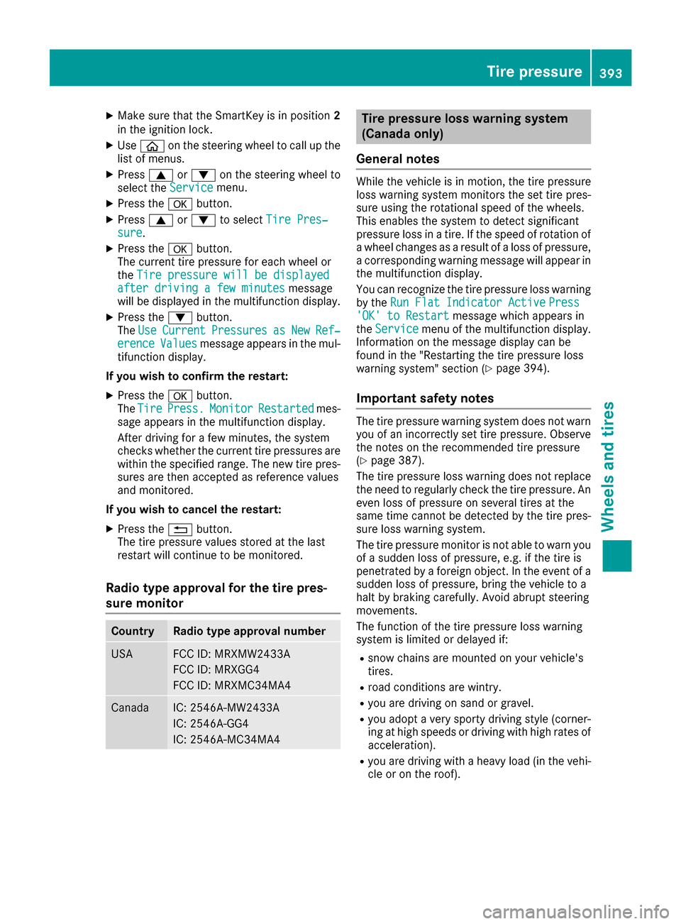
XMake sure that the SmartKey is in position2
in the ignition lock.
XUse ò on the steering wheel to call up the
list of menus.
XPress 9or: on the steering wheel to
select the Servicemenu.
XPress theabutton.
XPress 9or: to select Tire Pres‐sure.
XPress the abutton.
The current tire pressure for each wheel or
the Tire pressure will be displayed
after driving a few minutesmessage
will be displayed in the multifunction display.
XPress the :button.
The UseCurrentPressuresasNewRef‐erenceValuesmessage appears in the mul-
tifunction display.
If you wish to confirm the restart:
XPress the abutton.
The TirePress.MonitorRestartedmes-
sage appears in the multifunction display.
After driving for a few minutes, the system
checks whether the current tire pressures are
within the specified range. The new tire pres-
sures are then accepted as reference values
and monitored.
If you wish to cancel the restart:
XPress the %button.
The tire pressure values stored at the last
restart will continue to be monitored.
Radio type approval for the tire pres-
sure monitor
CountryRadio type approval number
USAFCC ID: MRXMW2433A
FCC ID: MRXGG4
FCC ID: MRXMC34MA4
CanadaIC: 2546A-MW2433A
IC: 2546A-GG4
IC: 2546A-MC34MA4
Tire pressure loss warning system
(Canada only)
General notes
While the vehicle is in motion, the tire pressure
loss warning system monitors the set tire pres-
sure using the rotational speed of the wheels.
This enables the system to detect significant
pressure loss in a tire. If the speed of rotation of
a wheel changes as a result of a loss of pressure,
a corresponding warning message will appear in
the multifunction display.
You can recognize the tire pressure loss warning
by the Run Flat Indicator Active
Press'OK' to Restartmessage which appears in
the Servicemenu of the multifunction display.
Information on the message display can be
found in the "Restarting the tire pressure loss
warning system" section (
Ypage 394).
Important safety notes
The tire pressure warning system does not warn you of an incorrectly set tire pressure. Observe
the notes on the recommended tire pressure
(
Ypage 387).
The tire pressure loss warning does not replace
the need to regularly check the tire pressure. An
even loss of pressure on several tires at the
same time cannot be detected by the tire pres-
sure loss warning system.
The tire pressure monitor is not able to warn you
of a sudden loss of pressure, e.g. if the tire is
penetrated by a foreign object. In the event of a
sudden loss of pressure, bring the vehicle to a
halt by braking carefully. Avoid abrupt steering
movements.
The function of the tire pressure loss warning
system is limited or delayed if:
Rsnow chains are mounted on your vehicle's
tires.
Rroad conditions are wintry.
Ryou are driving on sand or gravel.
Ryou adopt a very sporty driving style (corner-
ing at high speeds or driving with high rates of acceleration).
Ryou are driving with a heavy load (in the vehi-
cle or on the roof).
Tire pressure393
Wheels and tires
Z
Page 427 of 438

Useful information
i
This Operator's Manual describes all models
and all standard and optional equipment of
your vehicle available at the time of publica-
tion of the Operator's Manual. Country-spe-
cific differences are possible. Please note
that your vehicle may not be equipped with all
features described. This also applies to
safety-related systems and functions.
iRead the information on qualified specialist
workshops (Ypage 28).
Information regarding technical data
i
The data stated here specifically refers to a
vehicle with standard equipment. Consult an
authorized Mercedes-Benz Center for the
data for all vehicle variants and trim levels.
Vehicle electronics
Retrofitting two-way radios and
mobile phones (RF transmitters)
GWARNING
The electromagnetic radiation from modified
or incorrectly retrofitted RF-transmitters can
interfere with the vehicle electronics. This can compromise the operational safety of the
vehicle. There is a risk of an accident.
You should have all work to electrical and
electronic equipment carried out at a qualified
specialist workshop.
GWARNING
The electromagnetic radiation from incor-
rectly operated RF transmitters can interfere
with the vehicle electronics, for example:
Rif the RF transmitter is not connected with
an exterior antenna
Rthe exterior antenna has been installed
incorrectly or is not a low-reflection type
This can compromise the operational safety
of the vehicle. There is a risk of an accident.
Have the low-reflection exterior antenna
mounted at a qualified specialist workshop.
When operating RF transmitters in the vehi-
cle, always connect them with the low-reflec- tion exterior antenna.
!The operating permit may be invalidated if
the instructions for installation and use of RF
transmitters are not observed.
In particular, the following conditions must be complied with:
Ronly approved wavebands may be used.
Rcompliance with the maximum permissibleoutput in these wavebands is required.
Ronly approved antenna positions may be
used.
Excessive levels of electromagnetic radiation
may cause damage to your health and the health
of others. Using an exterior antenna takes into
account current scientific discussions relating
to the possible health hazards that may result
from electromagnetic fields.
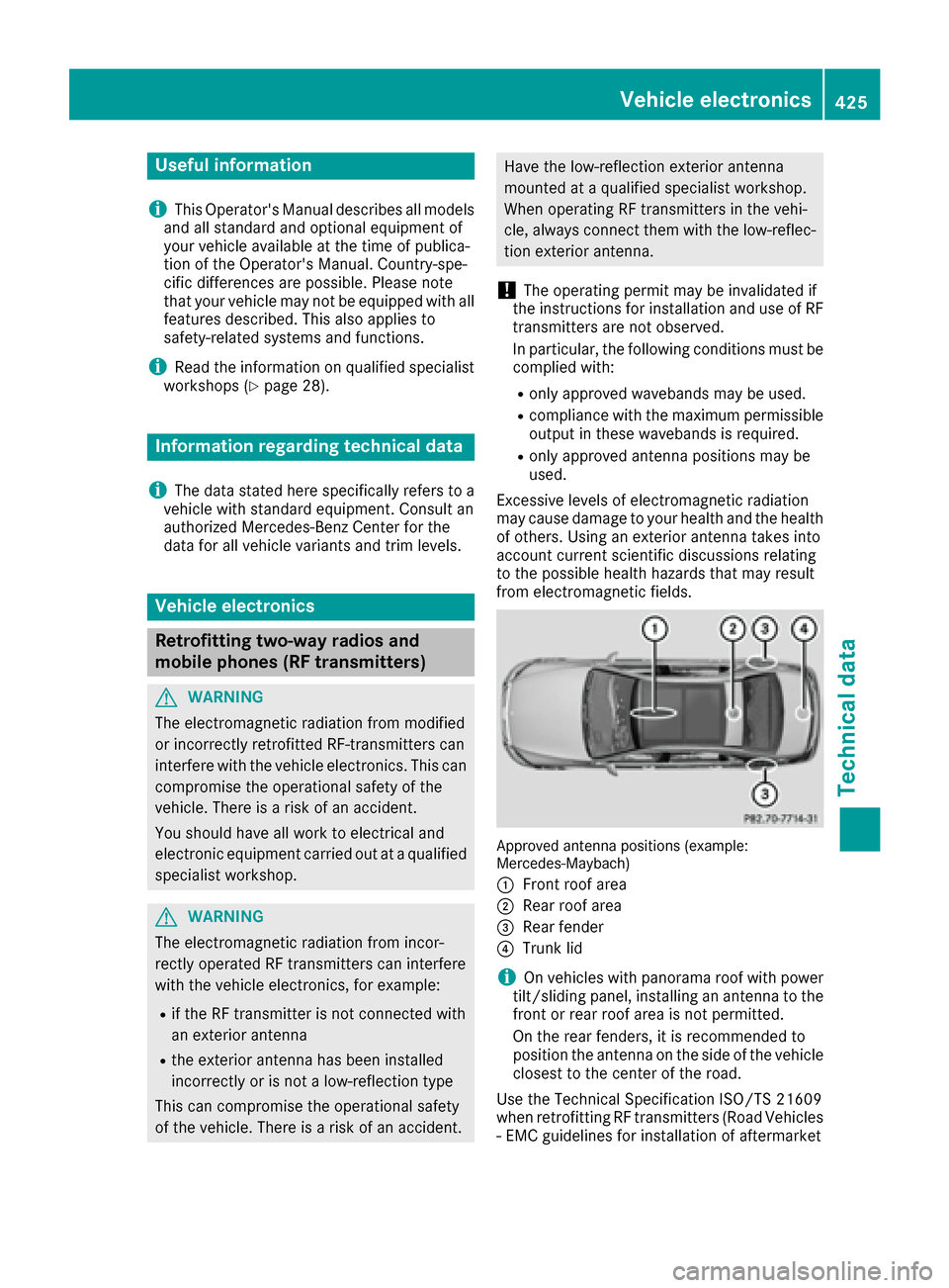
Approved antenna positions (example:
Mercedes‑ Maybach)
:
Front roof area
;Rear roof area
=Rear fender
?Trunk lid
iOn vehicles with panorama roof with power
tilt/sliding panel, installing an antenna to the
front or rear roof area is not permitted.
On the rear fenders, it is recommended to
position the antenna on the side of the vehicle
closest to the center of the road.
Use the Technical Specification ISO/TS 21609
when retrofitting RF transmitters (Road Vehicles
- EMC guidelines for installation of aftermarket
Vehicle electronics425
Technical data
Z
Page 428 of 438

radio frequency transmitting equipment).
Observe the legal requirements for retrofittings.
If your vehicle has installations for two-way radio
equipment, use the power supply or antenna
connections intended for use with the basic wir-
ing. Be sure to observe the manufacturer's addi-tional instructions when installing.
Deviations with respect to wavebands, maxi-
mum transmission outputs or antenna positions
must be approved by Mercedes-Benz.
The maximum transmission output (PEAK) at the
base of the antenna must not exceed the fol-
lowing values:
WavebandMaximum
transmission output
Short wave
3 - 54 MHz100 W
4 m waveband
74 - 78 MHz30 W
2 m waveband
144 - 174 MHz50 W
Trunked radio/Tetra
380 - 460 MHz10 W
70 cm waveband
400 - 460 MHz35 W
Mobile communications
(2G/3G/4G)10 W
The following can be used in the vehicle without
restrictions:
RRF transmitters with a maximum transmis-
sion output of up to 100 mW
RRF transmitters with transmitter frequencies
in the 380 - 410 MHz waveband and a maxi-
mum transmission output of up to 2 W
(trunked radio/Tetra)
RMobile telephones (2G/3G/4G)
There is no restriction for antenna positions on
the outside of the vehicle for the following wave-
bands:
RTrunked radio/Tetra
R70 cm waveband
R2G/3G/4G
Identification plates
Vehicle identification plate with vehi-
cle identification number (VIN)
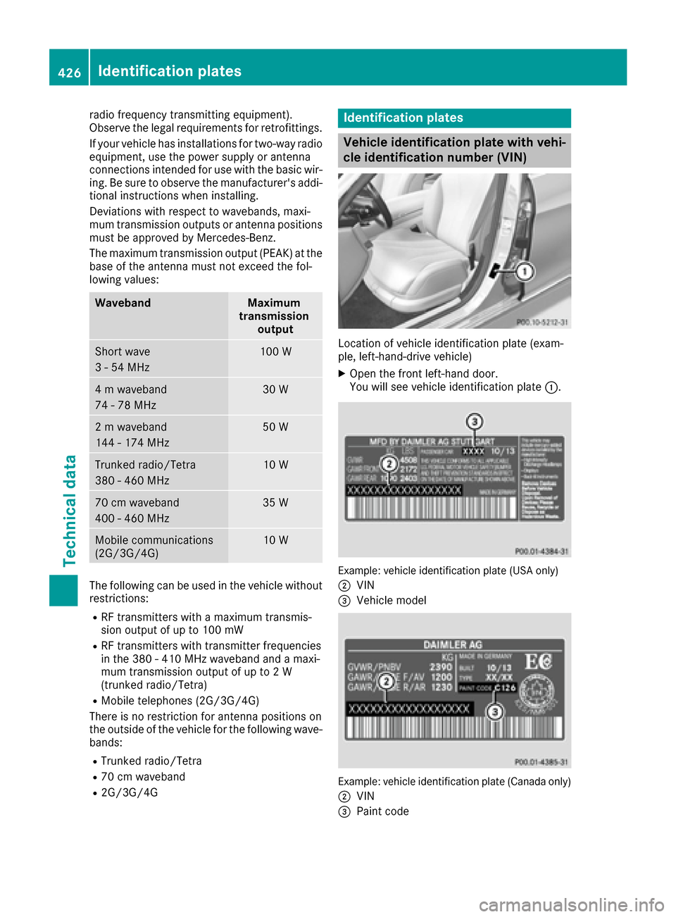
Location of vehicle identification plate (exam-
ple, left-hand-drive vehicle)
XOpen the front left-hand door.
You will see vehicle identification plate :.
Example: vehicle identification plate (USA only)
;
VIN
=Vehicle model
Example: vehicle identification plate (Canada only)
;
VIN
=Paint code
426Identification plates
Technical data