2016 MERCEDES-BENZ GLS SUV flat tire
[x] Cancel search: flat tirePage 15 of 397
Folding in/out (automatically
)....... 117
Folding in/out (electrically) ........... 117
Out of position (troubleshooting) ... 117
Parking position ............................. 118
Resetting ....................................... 117
Storing settings (memory func-
tion) ............................................... 118 F
Fault message see Display messages
Favourites
Overview ........................................ 304
Filler cap
see Fuel filler flap
Fire extinguisher ............................... 345
First-aid kit ......................................... 345
Fitting a wheel
Fitting a wheel ............................... 372
Lowering the vehicle ...................... 373
Preparing the vehicle ..................... 370
Raising the vehicl e......................... 371
Removing a whee l.......................... 372
Securing the vehicle against roll-
ing away ........................................ 370
Flat tyre
MOExtended tyre s......................... 347
Preparing the vehicle ..................... 346
TIREFIT kit ...................................... 348
see Emergency spare wheel
Floormat ............................................. 331
Foglamps (extended range) .............. 123
Folding the rear bench seat for-
wards/back ....................................... 315
Fording
Off-road ......................................... 175
On flooded roads ........................... 175
Frequencies
Garage door opener ....................... 328
Mobile phone ................................. 379
Two-way radio ................................ 379
Front-passenger front airbag deac-
tivation
Display message ............................ 268
Front-passenger front airbag deac-
tivation system
Operation ......................................... 50 Problems ......................................... 54
System self-test ............................... 53
Fuel
Additives ........................................ 383
Consumption statistics .................. 244
Displaying the current consump-
tion ................................................ 245
Displaying the rang e...................... 245
Driving tips .................................... 172
Fuel gaug e....................................... 35
Grade (petrol) ................................ 382
Important safety notes .................. 382
Low outside temperature s............. 384
Notes for Mercedes‑AMG vehi-
cles ................................................ 383
Problem (malfunction) ................... 165
Quality (diesel )............................... 383
Refuelling ....................................... 163
Tank content/reserve fue l............. 382
Fuel filler flap
Opening ......................................... 164
Fuel filter (white display message) .. 274
Fuel level
Calling up the range (on-board
computer) ...................................... 245
Gaug e.............................................. 35
Fuel tank
Capacity ........................................ 382
Problem (malfunction) ................... 165
Fuses
Allocation chart ............................. 359
Before changing ............................. 359
Dashboard fuse box ....................... 359
Fuse box in the engine compart-
ment .............................................. 360
Fuse box under rear bench sea t.... 360
Important safety notes .................. 359 G
Garage door opener Clearing the memory ..................... 328
Frequencies ................................... 328
General notes ................................ 326
Important safety notes .................. 326
Opening/closing the garage doo r..3 27
Problems when programming ....... .327 12
Index
Page 26 of 397
Lights display messag
e.................. 270
Power supply ................................. 238
Problem (fault) ............................... 239
Trailer load s................................... 390
Transmission
see Automatic transmission
Transmission position display ......... 158
Transporting the vehicle .................. 358
Travelling uphill
Brow of hill ..................................... 180
Driving downhill ............................. 180
Maximum gradient-climbing capa-
bility ............................................... 180
Trim pieces (cleaning instruc-
tions) .................................................. 343
Trip computer (on-board com-
puter) .................................................. 244
Trip meter
Calling up ....................................... 244
Resetting (on-board computer) ...... 245
Turn signals
Replacing bulbs (front) ................... 128
Switching on/of f........................... 122
TV
Operating (on-board computer) ..... 248
see Separate operating instructions
Two-way radio
Frequencies ................................... 379
Installation ..................................... 379
Transmission output (maximum) .... 379
Type identification plate
see Vehicle identification plate
Tyre inflation compressor
see TIREFIT kit
Tyre pressure
Calling up (on-board computer) ..... 367
Display message ............................ 283
Not reached (TIREFIT) .................... 350
Reached (TIREFIT) .......................... 350
Recommended ............................... 364
Tyre pressure loss warning
General notes ................................ 366
Important safety notes .................. 366
Restarting ...................................... 366
Tyre pressure monitor
Checking the tyre pressure elec-
tronically ........................................ 367
Function/note s............................. 367 General notes ................................ 367
Important safety notes .................. 367
Radio type approval for the tyre
pressure monitor ........................... 369
Restarting ...................................... 368
Warning lamp ................................. 302
Warning message .......................... 368
Tyres
Changing a whee l.......................... 369
Checking ........................................ 361
Direction of rotation ...................... 370
Display message ............................ 283
Important safety notes .................. 361
Information on driving .................... 361
M+S tyres ...................................... 363
MOExtended tyre s......................... 363
Replacing ....................................... 369
Service life ..................................... 362
Snow chains .................................. 364
Storing ........................................... 370
Summer tyres in winter ................. 363
Tyre size (data ).............................. 374
Tyre tread ...................................... 362
Wheel and tyre combinations ........ 374
see Flat tyre U
Unlocking Emergency unlocking ....................... 89
From inside the vehicle (central
unlocking button) ............................. 88
Upshift indicator (on-board com-
puter, Mercedes-AMG vehicles) ....... 255
USB devices
Connecting to the Media Inter-
face ............................................... 311 V
Vanity mirror (in sun visor) .............. 322
Vehicle
Correct use ...................................... 31
Data acquisition ............................... 31
Display message ............................ 285
Electronics ..................................... 379
Equipment ....................................... 27
Implied warranty .............................. 31
Individual settings .......................... 251 Index
23
Page 65 of 397
If the front-passenger seat of your vehicle is not
equipped with the automatic front-passenger
front airbag deactivation system, this is indica-
ted by a special sticker. The sticker is affixed to
the side of the dashboard on the front-
passenger side. The sticker is visible when you
open the front-passenger door.
If you turn the key to position 2in the ignition
lock, the PASSENGER AIR BAG OFF and
PASSENGER AIR BAG ON indicator lamps light
up briefly. However, they have no function and
do not indicate that there is an automatic front- passenger front airbag deactivation system.
In this case, never fit a rearward-facing child
restraint system on the front passenger seat
(Y page 62).
Observe the following information under "Rear-
ward-facing child restraint system"
(Y page 62) and "Forward-facing child
restraint system" (Y page 62) as well as infor-
mation on the suitable positioning of the child
restraint system (Y page 62).
Rearward-facing child restraint system If it is absolutely necessary to fit a rearward-
facing child restraint system to the front-
passenger seat, always make sure that the
front-passenger front airbag is disabled. Only if
the PASSENGER AIR BAG OFF indicator lamp is lit continuously (Y page 43) is the front-
passenger front airbag disabled.
Always observe the information on suitable
positioning of the child restraint system
(Y page 62) in addition to the child restraint
system manufacturer's installation and operat-
ing instructions.
Forward-facing child restraint system If it is absolutely necessary to fit a forward-
facing child restraint system to the front-
passenger seat, always move the front-
passenger seat as far back as possible. The
entire base of the child restraint system must
always rest on the seat cushion of the front-
passenger seat. The backrest of the child
restraint system must, as far as possible, lie flat against the backrest of the front-passenger
seat. The child restraint system must not touch the roof or be put under strain by the head
restraint. Adjust the angle of the seat backrest
and the head restraint position accordingly.
Always make sure that the shoulder belt strap is correctly routed from the vehicle belt outlet to
the shoulder belt guide on the child restraint
system. The shoulder belt strap must be routed
forwards and downwards from the vehicle belt
outlet. If necessary, adjust the vehicle belt out-
let and the front-passenger seat accordingly.
Always observe the information on suitable
positioning of the child restraint system
(Y page 62) in addition to the child restraint
system manufacturer's installation and operat-
ing instructions. Suitable positioning of the child
restraint system
Introduction Only child restraint systems that are approved in
accordance with ECE standard ECE R44 are per-
mitted for use in the vehicle.
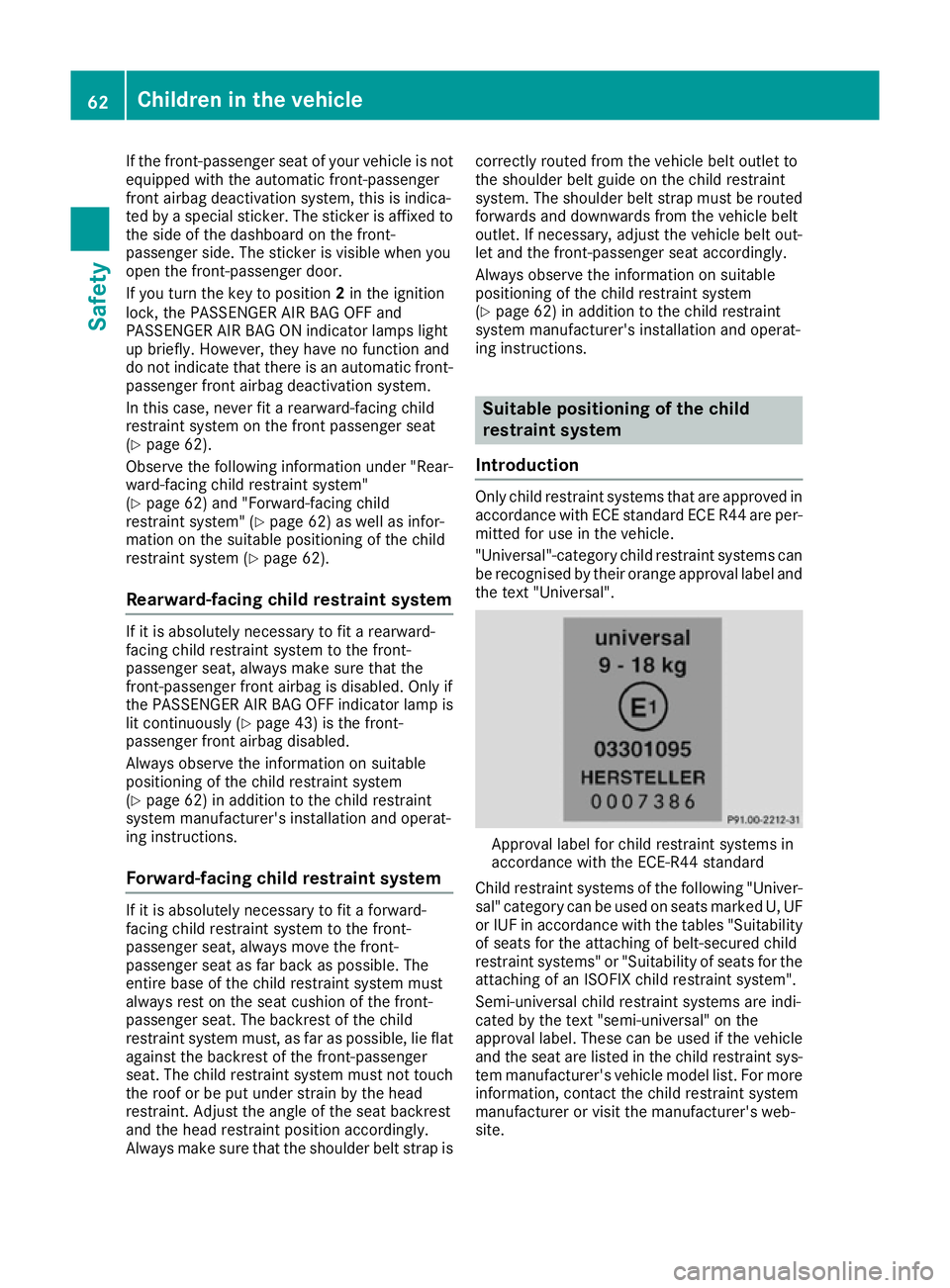
"Universal"-category child restraint systems can
be recognised by their orange approval label and the text "Universal". Approval label for child restraint systems in
accordance with the ECE-R44 standard
Child restraint systems of the following "Univer-
sal" category can be used on seats marked U, UF or IUF in accordance with the tables "Suitabilityof seats for the attaching of belt-secured child
restraint systems" or "Suitability of seats for the
attaching of an ISOFIX child restraint system".
Semi-universal child restraint systems are indi-
cated by the text "semi-universal" on the
approval label. These can be used if the vehicle
and the seat are listed in the child restraint sys-
tem manufacturer's vehicle model list. For more information, contact the child restraint system
manufacturer or visit the manufacturer's web-
site. 62
Children in the vehicleSafety
Page 66 of 397
Child restraint system on the front-
passenger seat –
if it is absolutely necessary to
secure a child in a child restraint system on the front-passenger seat:
X Always pay attention to the instructions under
"Child restraint system on the front-
passenger seat" (Y page 61).
There, you will also find instructions on how to
correctly route the shoulder belt strap from
the vehicle belt outlet to the shoulder belt
guide on the child restraint system
(Y page 62).
X Move the front-passenger seat as far back as
possible.
X Move the backrest to an almost upright posi-
tion.
The entire base of the child restraint system
must always rest on the seat cushion of the front-passenger seat. The backrest of the
forward-facing child restraint system must, as far as possible, be resting on the backrest of
the front-passenger seat. The child restraint
system must not touch the roof or be put
under strain by the head restraint. Adjust the
angle of the seat backrest and the head
restraint position accordingly. Also observe
the child restraint system manufacturer's
installation instructions.
X Move the seat cushion angle to the highest,
most vertical position.
Installing a child restraint system on a rear
seat in the second row
X Move the backrest of the rear seat in the sec-
ond row to an almost vertical position
(Y page 107).
Suitability of the seats for attaching a belted child restraint system If you use a baby car seat of category 0 or 0+ or a rearward-facing child restraint system of category
I on a rear seat, you must adjust the driver's or front-passenger seat so that the seat does not touch the child restraint system.
If you use a forward-facing child restraint system of category I, you must remove the head restraint
from the respective seat, if possible (Y page 104). The backrest of the child restraint system must,
as far as possible, rest flat against the backrest of the seat.
Make sure that the child's feet do not touch the front seat. If necessary, move the front seat forwards
slightly (Y page 104).
For certain child restraint systems in weight categories II or III, this can mean that the area of use
is restricted. The maximum size setting of the child restraint system may not be possible due to
possible contact with the roof.
In addition, always observe the information in the "Child restraint system" section (Y page 58) and
the child restraint system manufacturer's installation instructions.
When you remove the child restraint system, you must replace the head restraints again immedi-
ately (Y page 104). All vehicle occupants must adjust their head restraints correctly before the
journey.
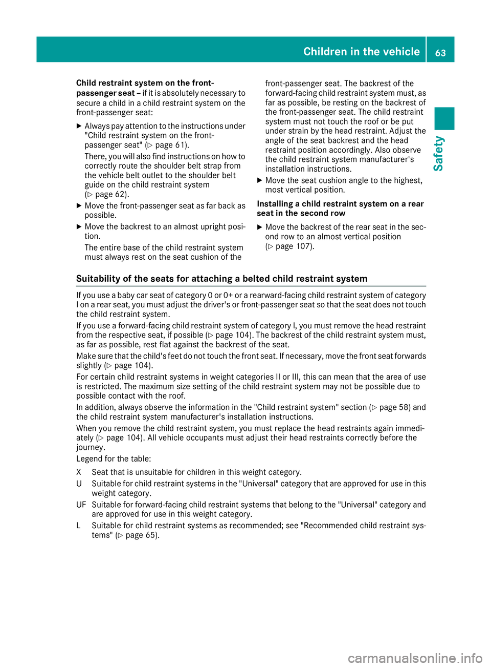
Legend for the table:
XS eat that is unsuitable for children in this weight category.
US uitable for child restraint systems in the "Universal" category that are approved for use in this
weight category.
UF Suitable for forward-facing child restraint systems that belong to the "Universal" category and are approved for use in this weight category.
LS uitable for child restraint systems as recommended; see "Recommended child restraint sys-
tems" (Y page 65). Children in the vehicle
63Safety Z
Page 349 of 397
the vehicle. For more information on which tools
are required to perform a wheel change on your vehicle, consult a qualified specialist workshop.
Necessary tyre-changing tools may include, for
example:
R jack
R wheel chock
R wheel wrench
R ratchet ring spanner
R centring pin
i The jack weighs approximately 3.4 kg.
The maximum load-bearing capacity of the
jack can be found on the adhesive label on the
jack.
The jack is maintenance-free. If there is a
malfunction, please contact a qualified spe-
cialist workshop.
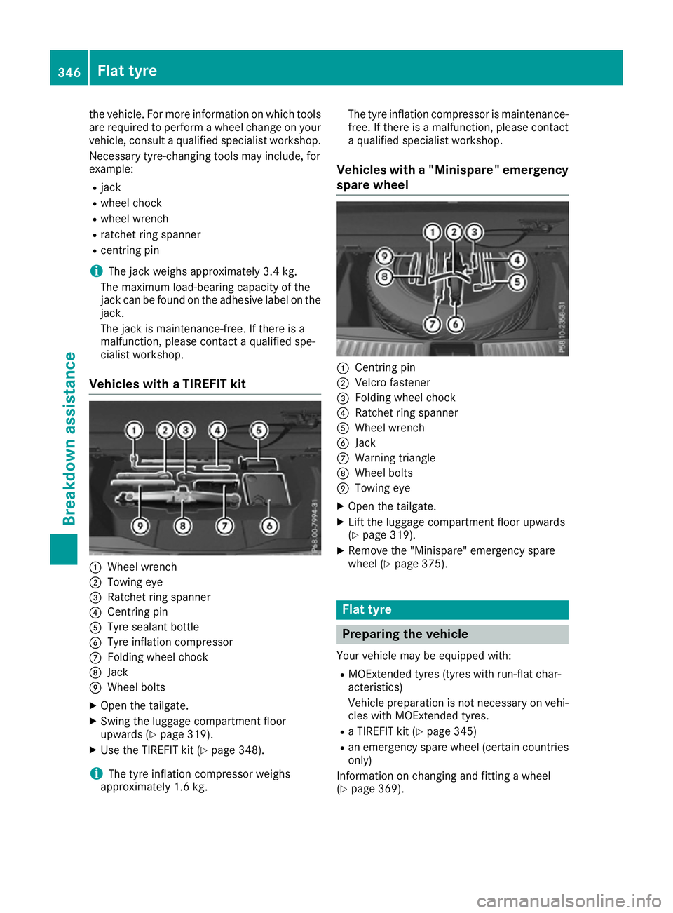
Vehicles with a TIREFIT kit :
Wheel wrench
; Towing eye
= Ratchet ring spanner
? Centring pin
A Tyre sealant bottle
B Tyre inflation compressor
C Folding wheel chock
D Jack
E Wheel bolts
X Open the tailgate.
X Swing the luggage compartment floor
upwards (Y page 319).
X Use the TIREFIT kit (Y page 348).
i The tyre inflation compressor weighs
approximately 1.6 kg. The tyre inflation compressor is maintenance-
free. If there is a malfunction, please contact a qualified specialist workshop.
Vehicles with a "Minispare" emergency
spare wheel :
Centring pin
; Velcro fastener
= Folding wheel chock
? Ratchet ring spanner
A Wheel wrench
B Jack
C Warning triangle
D Wheel bolts
E Towing eye
X Open the tailgate.
X Lift the luggage compartment floor upwards
(Y page 319).
X Remove the "Minispare" emergency spare
wheel (Y page 375). Flat tyre
Preparing the vehicle
Your vehicle may be equipped with: R MOExtended tyres (tyres with run-flat char-
acteristics)
Vehicle preparation is not necessary on vehi- cles with MOExtended tyres.
R a TIREFIT kit (Y page 345)
R an emergency spare wheel (certain countries
only)
Information on changing and fitting a wheel
(Y page 369). 346
Flat tyreBreakdown assistance
Page 351 of 397
may be used as a temporary measure. Make
sure that you use the proper size and type
(summer or winter tyres).
i Vehicles with MOExtended tyres are not
equipped with a TIREFIT kit at the factory. It is therefore recommended that you additionally
equip your vehicle with a TIREFIT kit if you fit
tyres that do not feature run-flat characteris-
tics, e.g. winter tyres. A TIREFIT kit can be
obtained from a qualified specialist work-
shop.
Important safety notes G
WARNING
When driving in emergency mode, the driving characteristics deteriorate, e.g. when corner-
ing, accelerating quickly and when braking.
There is a risk of accident.
Do not exceed the stated maximum speed.
Avoid abrupt steering and driving manoeu-
vres, and driving over obstacles (kerbs, pot-
holes, off-road). This applies in particular to a laden vehicle.
Stop driving in emergency mode if:
R you hear banging noises.
R the vehicle starts to shake.
R you see smoke and smell rubber.
R ESP ®
is intervening constantly.
R there are tears in the sidewalls of the tyre.
After driving in emergency mode, have the
wheel rims checked at a qualified specialist
workshop with regard to their further use. The
faulty tyre must be replaced. TIREFIT kit
Important safety notes TIREFIT is a tyre sealant.
You can use TIREFIT to seal punctures of up to
4 mm, particularly those in the tyre tread. You
can use TIREFIT at outside temperatures down
to
Ò20 †. G
WARNING
In the following situations, the tyre sealant is
unable to provide sufficient breakdown assis- tance, as it is unable to seal the tyre properly:
R there are cuts or punctures in the tyre
larger than those mentioned above.
R the wheel rim is damaged.
R you have driven at very low tyre pressures
or on a flat tyre.
There is a risk of an accident.
Do not drive any further. Contact a qualified
specialist workshop. G
WARNING
The tyre sealant is harmful and causes irrita-
tion. It must not come into contact with your
skin, eyes or clothing or be swallowed. Do not inhale TIREFIT fumes. Keep tyre sealant away
from children. There is a risk of injury.
If you come into contact with the tyre sealant,
observe the following:
R Rinse off the tyre sealant from your skin
immediately with water.
R If the tyre sealant comes into contact with
your eyes, immediately rinse them thor-
oughly with clean water.
R If tyre sealant is swallowed, immediately
rinse your mouth out thoroughly and drink
plenty of water. Do not induce vomiting,
and seek medical attention immediately.
R Immediately change out of clothing which
has come into contact with tyre sealant.
R If an allergic reaction occurs, seek medical
attention immediately.
! Do not operate the tyre inflation compres-
sor for longer than eight minutes at a time
without a break. It may otherwise overheat.
The tyre inflation compressor can be oper-
ated again once it has cooled down.
Comply with the manufacturer's safety instruc-
tions on the sticker on the tyre inflation com-
pressor. 348
Flat tyreBreakdown assistance
Page 352 of 397
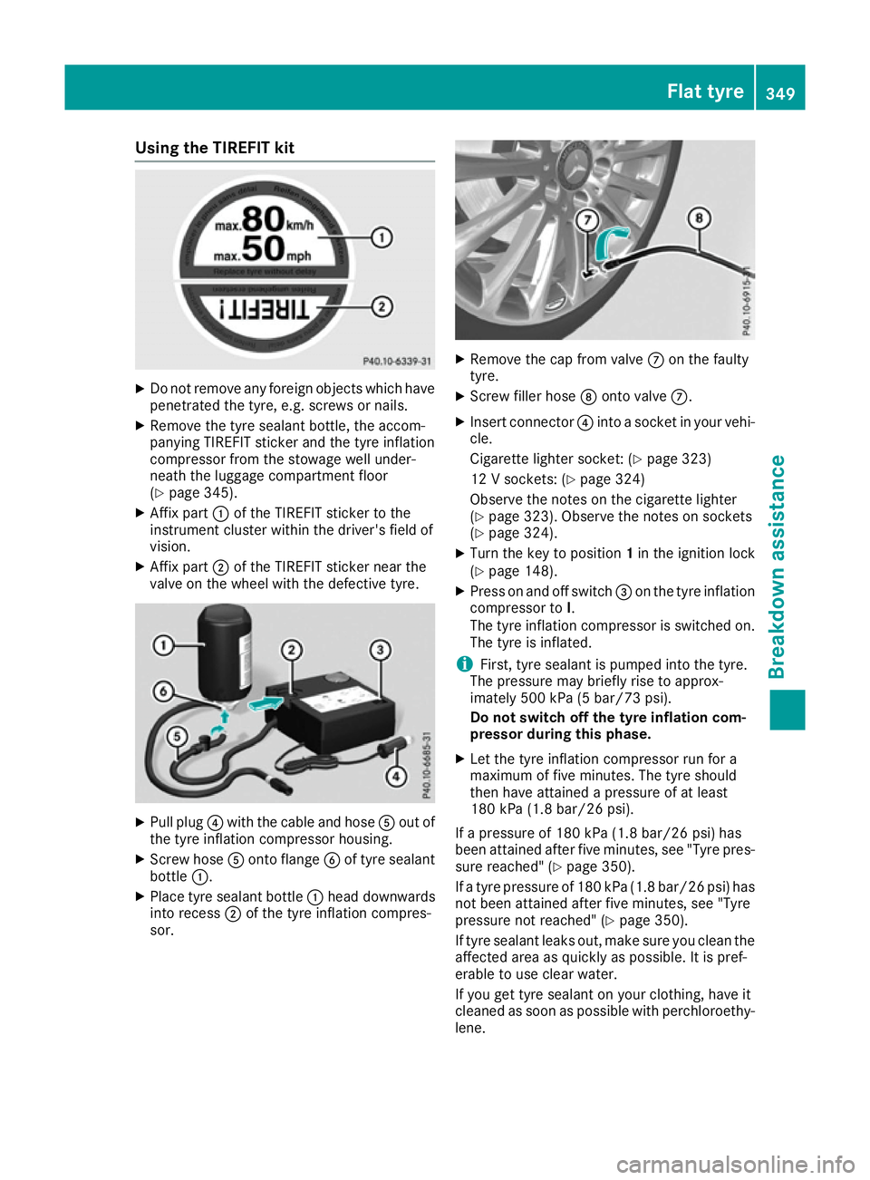
Using the TIREFIT kit
X
Do not remove any foreign objects which have
penetrated the tyre, e.g. screws or nails.
X Remove the tyre sealant bottle, the accom-
panying TIREFIT sticker and the tyre inflation
compressor from the stowage well under-
neath the luggage compartment floor
(Y page 345).
X Affix part :of the TIREFIT sticker to the
instrument cluster within the driver's field of
vision.
X Affix part ;of the TIREFIT sticker near the
valve on the wheel with the defective tyre. X
Pull plug ?with the cable and hose Aout of
the tyre inflation compressor housing.
X Screw hose Aonto flange Bof tyre sealant
bottle :.
X Place tyre sealant bottle :head downwards
into recess ;of the tyre inflation compres-
sor. X
Remove the cap from valve Con the faulty
tyre.
X Screw filler hose Donto valve C.
X Insert connector ?into a socket in your vehi-
cle.
Cigarette lighter socket: (Y page 323)
12 V sockets: (Y page 324)
Observe the notes on the cigarette lighter
(Y page 323). Observe the notes on sockets
(Y page 324).
X Turn the key to position 1in the ignition lock
(Y page 148).
X Press on and off switch =on the tyre inflation
compressor to I.
The tyre inflation compressor is switched on.
The tyre is inflated.
i First, tyre sealant is pumped into the tyre.
The pressure may briefly rise to approx-
imately 500 kPa (5 bar/73 psi).
Do not switch off the tyre inflation com-
pressor during this phase.
X Let the tyre inflation compressor run for a
maximum of five minutes. The tyre should
then have attained a pressure of at least
180 kPa (1.8 bar/26 psi).
If a pressure of 180 kPa (1.8 bar/26 psi) has
been attained after five minutes, see "Tyre pres-
sure reached" (Y page 350).
If a tyre pressure of 180 kPa (1.8 bar/26 psi) has not been attained after five minutes, see "Tyre
pressure not reached" (Y page 350).
If tyre sealant leaks out, make sure you clean the
affected area as quickly as possible. It is pref-
erable to use clear water.
If you get tyre sealant on your clothing, have it
cleaned as soon as possible with perchloroethy- lene. Flat tyre
349Breakdown assistance Z
Page 353 of 397
Tyre pressure not reached
If a pressure of 180 kPa (1.8 bar/26 psi) has not
been attained after five minutes:
X Switch off the tyre inflation compressor.
X Unscrew the filler hose from the valve of the
faulty tyre.
Please note that tyre sealant may leak out
when unscrewing the filler hose.
X Very slowly drive forwards or reverse approx-
imately 10 m.
X Pump up the tyre again.
After a maximum of five minutes the tyre
pressure must be at least 180 kPa (1.8 bar/
26 psi). G
WARNING
If the required tyre pressure is not reached
after the specified time, the tyre is too badly
damaged. The tyre sealant cannot repair the
tyre in this instance. Damaged tyres and a tyre pressure that is too low can significantly
impair the vehicle's braking and driving char-
acteristics. There is a risk of accident.
Do not continue driving. Contact a qualified
specialist workshop.
Tyre pressure reached G
WARNING
A tyre temporarily sealed with tyre sealant
impairs the driving characteristics and is not
suitable for higher speeds. There is a risk of
accident.
You should therefore adapt your driving style
accordingly and drive carefully. Do not exceed the specified maximum speed with a tyre that
has been repaired using tyre sealant.
The maximum permissible speed for a tyre
sealed with tyre sealant is 80 km/h. The upper
part of the TIREFIT sticker must be affixed to the
instrument cluster where it will be easily seen by
the driver.
! After use, excess tyre sealant may run out of
the filler hose. This could cause stains.
Therefore, place the filler hose in the plastic
bag which contained the TIREFIT kit. H
Environmental note
Have the used tyre sealant bottle disposed of professionally, e.g. at a qualified specialist
workshop.
If a tyre pressure of 180 kPa (1.8 bar/26 psi) has been attained after five minutes:
X Switch off the tyre inflation compressor.
X Unscrew the filler hose from the valve of the
faulty tyre.
X Stow the tyre sealant bottle, the tyre inflation
compressor and the warning triangle.
X Pull away immediately.
X Stop after driving for approximately ten
minutes and check the tyre pressure with the
tyre inflation compressor.
The tyre pressure must now be at least
130 kPa (1.3 bar/19 psi). G
WARNING
If the required tyre pressure is not reached
after driving for a short period, the tyre is too badly damaged. The tyre sealant cannot
repair the tyre in this instance. Damaged tyres and a tyre pressure that is too low can signif-
icantly impair the vehicle's braking and driv-
ing characteristics. There is a risk of accident.
Do not continue driving. Contact a qualified
specialist workshop.
i In your vehicle, you will find a sticker with
the Mercedes-Benz Service24h telephone
number, e.g. on the B-pillar on the driver's
side.
X Correct the tyre pressure if it is still at least
130 kPa (1.3 ba r/19 psi). See the tyre pres-
sure table on the fuel filler flap for values.
X To increase the tyre pressure: switch on
the tyre inflation compressor. 350
Flat tyreBreakdown assistance