2016 MERCEDES-BENZ GLE load capacity
[x] Cancel search: load capacityPage 23 of 450
Average weight of the vehicle
occupants (definition) .................... 406
Bar (definition) ............................... 406
Changing a wheel .......................... 408
Characteristics .............................. 406
Checking ........................................ 388
Curb weight (definition) ................. 407
Definition of terms ......................... 406
Direction of rotation ...................... 409
Display message ............................ 309
Distribution of the vehicle occu-
pants (definition) ............................ 408
DOT (Department of Transporta-
tion) (definition) ............................. 406
DOT, Tire Identification Number
(TIN) ............................................... 405
GAWR (Gross Axle Weight Rating)
(definition) ..................................... 406
General notes ................................ 413
GTW (Gross Trailer Weight) (defi-
nition) ............................................ 407
GVW (Gross Vehicle Weight) (def-
inition) ........................................... 407
GVWR (Gross Vehicle Weight Rat-
ing) (definition) .............................. 407
Important safety notes .................. 387
Increased vehicle weight due to
optional equipment (definition) ...... 406
Information on driving .................... 387
Kilopascal (kPa) (definition) ........... 407
Labeling (overview) ........................ 403
Load bearing index (definition) ...... 408
Load index ..................................... 405
Load index (definition) ................... 407
M+S tires ....................................... 389
Maximum load on a tire (defini-
tion) ............................................... 407
Maximum loaded vehicle weight
(definition) ..................................... 407
Maximum permissible tire pres-
sure (definition) ............................. 407
Maximum tire load ......................... 405
Maximum tire load (definition) ....... 407
MOExtended tires .......................... 389
Optional equipment weight (defi-
nition) ............................................ 408
PSI (pounds per sq uare inch) (def-
i
nition) ........................................... 407 Replacing ....................................... 408
Service life ..................................... 388
Sidewall (definition) ....................... 408
Speed rating (definition) ................ 407
Storing ........................................... 409
Structure and characteristics
(definition) ..................................... 406
Temperature .................................. 402
TIN (Tire Identification Number)
(definition) ..................................... 408
Tire bead (definition) ...................... 407
Tire pressure (definition) ................ 407
Tire pressures (recommended) ...... 406
Tire size (data) ............................... 413
Tire size designation, load-bearing
capacity, speed rating .................... 403
Tire tread ....................................... 388
Tire tread (definition) ..................... 407
Total load limit (definition) ............. 408
Traction ......................................... 402
Traction (definition) ....................... 408
Tread wear ..................................... 402
TWR (permissible trailer drawbar
noseweight) (definition) ................. 408
Uniform Tire Quality Grading
Standards ...................................... 401
Uniform Tire Quality Grading
Standards (definition) .................... 406
Wear indicator (definition) ............. 408
Wheel and tire combination ........... 414
Wheel rim (definition) .................... 406
see Flat tire
Top Tether ............................................ 62
Tow-starting
Emergency engine starting ............ 383
Important safety notes .................. 381
Towing a trailer
Axle load, permissible .................... 445
Cleaning the trailer tow hitch ......... 366
Coupling up a trailer ...................... 259
Decoupling a trailer ....................... 261
Driving tips .................................... 257
ESP ®
(Electronic Stability Pro-
gram) ............................................... 73
Important safety notes .................. 256
Installing the ball coupling ............. 258
Lights display message .................. 292
Mo u nting dimensions .................... 444 Index 21
Page 335 of 450
! The backrest is heavy. Therefore, take care
when folding it down. Make sure that the head
restraints are pushed all the way in so that the
backrests and seat cushions are not dam-
aged.
Observe the loading guidelines ( Y
page 329).
The left-hand and right-hand rear seat backrests
can be folded forwards separately to increase
the cargo compartment capacity.
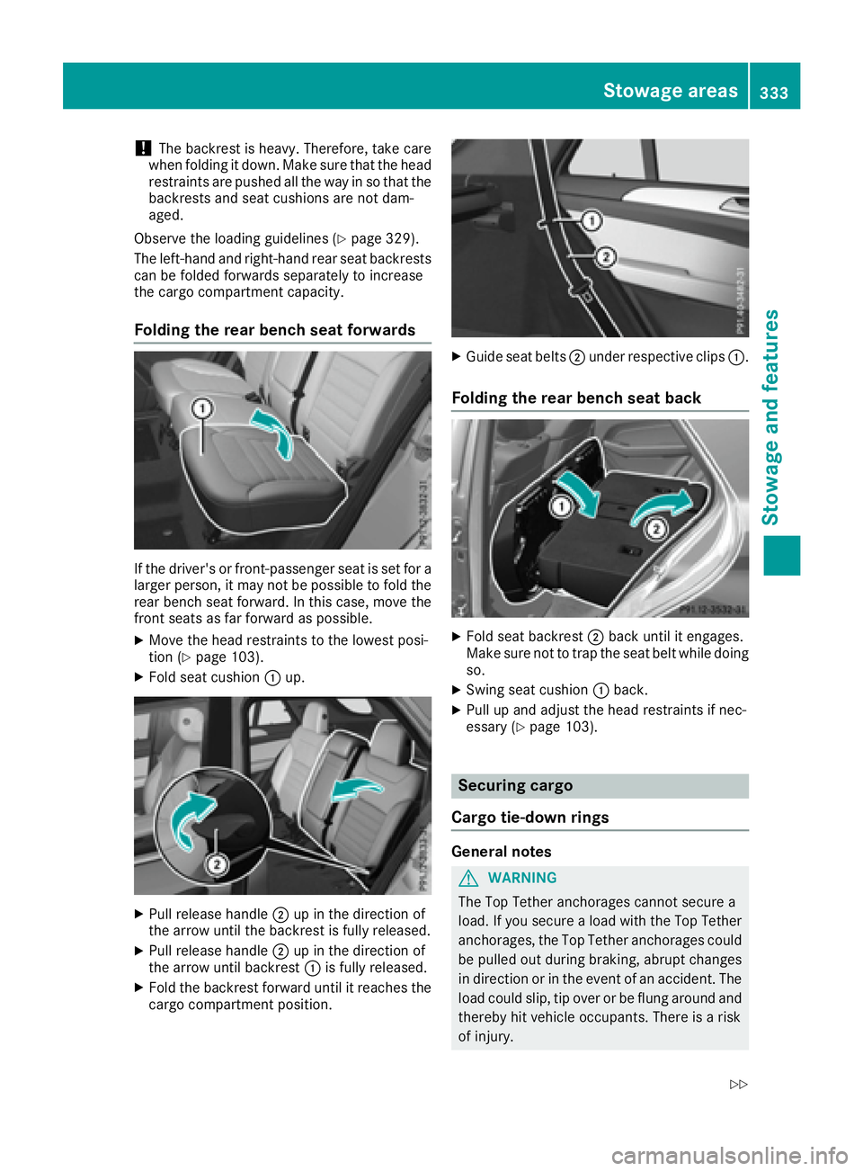
Folding the rear bench seat forwards
If the driver's or front-passenger seat is set for a
larger person, it may not be possible to fold the
rear bench seat forward. In this case, move the
front seats as far forward as possible. X
Move the head restraints to the lowest posi-
tion ( Y
page 103).X
Fold seat cushion �C up.
X
Pull release handle �D up in the direction of
the arrow until the backrest is fully released. X
Pull release handle �D up in the direction of
the arrow until backrest �C is fully released.X
Fold the backrest forward until it reaches the
cargo compartment position. X
Guide seat belts �D under respective clips �C .
Folding the rear bench seat back
X
Fold seat backrest �D back until it engages.
Make sure not to trap the seat belt while doing
so. X
Swing seat cushion �C back.X
Pull up and adjust the head restraints if nec-
essary ( Y
page 103).
Securing cargo
Cargo tie-down rings
General notes
G WARNING
The Top Tether anchorages cannot secure a
load. If you secure a load with the Top Tether
anchorages, the Top Tether anchorages could
be pulled out during braking, abrupt changes
in direction or in the event of an accident. The
load could slip, tip over or be flung around and
thereby hit vehicle occupants. There is a risk
of injury.Stowage areas 333
Stowage and features Z
Page 341 of 450
An incorrectly secured roof carrier or roof load
may become detached from the vehicle. You
must therefore ensure that you observe the roof
carrier manufacturer's installation instructions.
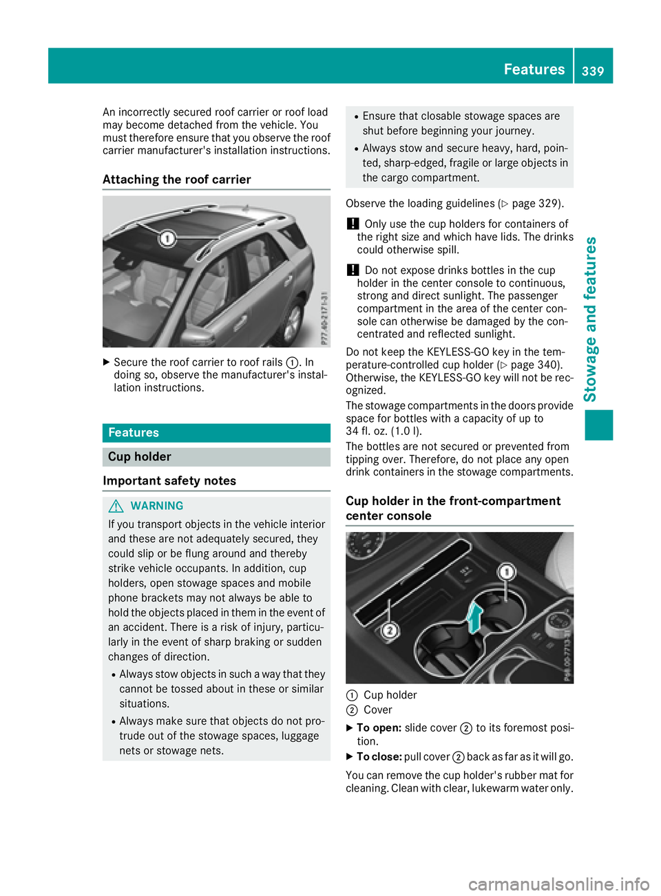
Attaching the roof carrier X
Secure the roof carrier to roof rails �C . In
doing so, observe the manufacturer's instal-
lation instructions.
Features
Cup holder
Important safety notes
G WARNING
If you transport objects in the vehicle interior
and these are not adequately secured, they
could slip or be flung around and thereby
strike vehicle occupants. In addition, cup
holders, open stowage spaces and mobile
phone brackets may not always be able to
hold the objects placed in them in the event of
an accident. There is a risk of injury, particu-
larly in the event of sharp braking or sudden
changes of direction. R
Always stow objects in such a way that they
cannot be tossed about in these or similar
situations. R
Always make sure that objects do not pro-
trude out of the stowage spaces, luggage
nets or stowage nets. R
Ensure that closable stowage spaces are
shut before beginning your journey. R
Always stow and secure heavy, hard, poin-
ted, sharp-edged, fragile or large objects in
the cargo compartment.
Observe the loading guidelines ( Y
page 329).
! Only use the cup holders for containers of
the right size and which have lids. The drinks
could otherwise spill.
! Do not expose drinks bottles in the cup
holder in the center console to continuous,
strong and direct sunlight. The passenger
compartment in the area of the center con-
sole can otherwise be damaged by the con-
centrated and reflected sunlight.
Do not keep the KEYLESS-GO key in the tem-
perature-controlled cup holder ( Y
page 340).
Otherwise, the KEYLESS-GO key will not be rec-
ognized.
The stowage compartments in the doors provide
space for bottles with a capacity of up to
34 fl. oz. (1.0 l).
The bottles are not secured or prevented from
tipping over. Therefore, do not place any open
drink containers in the stowage compartments.
Cup holder in the front-compartment
center console
�C
Cup holder
�D
Cover X
To open: slide cover �D to its foremost posi-
tion. X
To close: pull cover �D back as far as it will go.
You can remove the cup holder's rubber mat for
cleaning. Clean with clear, lukewarm water only. Features 339
Sto wag e an d features Z
Page 372 of 450
X
Open the tailgate. X
Lift the cargo compartment floor upwards
( Y
page 337).X
Remove the "Minispare" emergency spare
wheel ( Y
page 427).
Flat tire
Preparing the vehicle Your vehicle may be equipped with: R
MOExtended tires (tires with run-flat proper-
ties)
Vehicle preparation is not necessary on vehi-
cles with MOExtended tires R
a TIREFIT kit ( Y
page 369)R
an emergency spare wheel (only for certain
countries)
Information on changing and mounting wheels
( Y
page 408). X
Stop the vehicle on solid, non-slippery and
level ground, as far away as possible from
traffic. X
Switch on the hazard warning lamps. X
Secure the vehicle against rolling away
( Y
page 178).X
If possible, bring the front wheels into the
straight-ahead position. X
Vehicles with the AIRMATIC package:
make sure that the normal vehicle level is
selected ( Y
page 207).X
Vehicles with the Off-Road Engineering
package: make sure that the normal vehicle
level is selected ( Y
page 201).X
Switch off the engine. X
Vehicles without KEYLESS-GO: remove the
SmartKey from the ignition lock. X
Vehicles with KEYLESS-GO: open the driv-
er's door.
The on-board electronics now have status 0 .
This is the same as the SmartKey having been
removed. X
Vehicles with KEYLESS-GO: remove the
Start/Stop button from the ignition lock
( Y
page 146).X
Make sure that the engine cannot be started
via your smartphone ( Y
page 148).X
Make sure that the passengers are not endan-
gered as they do so. Make sure that no one is
near the danger area while a wheel is being changed. Anyone who is not directly assisting
in the wheel change should, for example,
stand behind the barrier. X
Get out of the vehicle. Pay attention to traffic
conditions when doing so. X
Close the driver's door. X
Unload heavy luggage.
i Only operate the tire inflation compressor
using a 12 V socket, even if the ignition is
turned off ( Y
page 343).
An emergency cut-out ensures that the on-
board voltage does not drop too low. If the on-
board voltage is too low, the power to the
sockets is automatically cut. This ensures
that there is sufficient power to start the
engine.
MOExtended tires (tires with run-flat
properties)
General notes With MOExtended tires (tires with run flat char-
acteristics), you can continue to drive your vehi-
cle even if there is a total loss of pressure in one
or more tires. The affected tire must not show
any clearly visible damage.
You can recognize MOExtended tires by the
MOExtended marking which appears on the
sidewall of the tire. You will find this marking
next to the tire size designation, the load-bear-
ing capacity and the speed index ( Y
page 403).
MOExtended tires may only be used in conjunc-
tion with an active tire pressure loss warning
system or with an active tire pressure monitor.
If a pressure loss warning message appears
in the multifunction display: R
observe the instructions in the display mes-
sages ( Y
page 309). R
check the tire for damage. R
if driving on, observe the following notes.
The driving distance possible in run-flat mode is
approximately 50 miles (80 km) when the vehi-
cle is partially laden and approximately 18 miles
(30 km) when the vehicle is fully laden.
In addition to the vehicle load, the driving dis-
tance possible depends upon: R
vehicle speed R
road condition R
outside temperature370
Flat tire
Breakdown assitance
Page 401 of 450
able cargo and luggage load capacity is
650 lbs (1400 - 750 (5 x 150) = 650 lbs). X
Step 5: Determine the combined weight of
luggage and cargo being loaded on the vehi-
cle. That weight may not safely exceed the
available cargo and luggage load capacity cal-
culated in step 4.
Loading the vehicle 399
Wheels and tires Z
Page 409 of 450
Speed rating The speed rating is part of the tire identification.
It specifies the speed range for which the tire is
approved.
GTW (Gross Trailer Weight) The GTW is the weight of a trailer including the
weight of the load, luggage, accessories etc. on
the trailer.
GVW (Gross Vehicle Weight) The gross vehicle weight includes the weight of
the vehicle including fuel, tools, the spare wheel,
accessories installed, occupants, luggage and
the drawbar noseweight, if applicable. The gross
vehicle weight must not exceed the gross vehi-
cle weight rating GVWR as specified on the vehi-
cle identification plate on the B-pillar on the
driver's side.
GVWR (Gross Vehicle Weight Rating) The GVWR is the maximum permissible gross
weight of a fully loaded vehicle (the weight of the
vehicle including all accessories, occupants,
fuel, luggage and the drawbar noseweight, if
applicable). The gross vehicle weight rating is
specified on the vehicle identification plate on
the B-pillar on the driver's side.
Maximum loaded vehicle weight The maximum weight is the sum of: R
the curb weight of the vehicle R
the weight of the accessories R
the load limit R
the weight of the factory installed optional
equipment
Kilopascal (kPa)
Metric unit for tire pressure. 6.9 kPa corre-
sponds to 1 psi. Another unit for tire pressure is
bar. 100 kilopascals (kPa) are the equivalent of
1 bar.
Load index
In addition to the load-bearing index, the load
index may also be imprinted on the sidewall of
the tire. This specifies the load-bearing capacity
more precisely.
Curb weight
The weight of a vehicle with standard equipment
including the maximum capacity of fuel, oil and
coolant. It also includes the air-conditioning sys- tem and optional equipment if these are instal-
led in the vehicle, but does not include passen-
gers or luggage.
Maximum load rating The maximum tire load is the maximum permis-
sible weight in kilograms or lbs for which a tire is
approved.
Maximum permissible tire pressure Maximum permissible tire pressure for one tire.
Maximum load on one tire Maximum load on one tire. This is calculated by
dividing the maximum axle load of one axle by
two.
PSI (pounds per square inch) A standard unit of measure for tire pressure.
Aspect ratio Relationship between tire height and tire width
in percent.
Tire pressure This is pressure inside the tire applying an out-
ward force to each square inch of the tire's sur-
face. The tire pressure is specified in pounds per
square inch (psi), in kilopascal (kPa) or in bar.
The tire pressure should only be corrected when
the tires are cold.
Cold tire pressure The tires are cold: R
if the vehicle has been parked with the tires
out of direct sunlight for at least three hours
and R
if the vehicle has not been driven further than
1 mile (1.6 km)
Tread
The part of the tire that comes into contact with
the road.
Bead
The tire bead ensures that the tire sits securely
on the wheel. There are several steel wires in the
bead to prevent the tire from coming loose from
the wheel rim.All about wheels and tires 407
Wheels and tires Z
Page 412 of 450
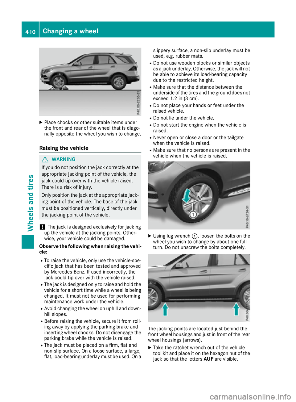
X
Place chocks or other suitable items under
the front and rear of the wheel that is diago-
nally opposite the wheel you wish to change.
Raising the vehicle
G WARNING
If you do not position the jack correctly at the
appropriate jacking point of the vehicle, the
jack could tip over with the vehicle raised.
There is a risk of injury.
Only position the jack at the appropriate jack-
ing point of the vehicle. The base of the jack
must be positioned vertically, directly under
the jacking point of the vehicle.
! The jack is designed exclusively for jacking
up the vehicle at the jacking points. Other-
wise, your vehicle could be damaged.
Observe the following when raising the vehi-
cle: R
To raise the vehicle, only use the vehicle-spe-
cific jack that has been tested and approved
by Mercedes-Benz. If used incorrectly, the
jack could tip over with the vehicle raised. R
The jack is designed only to raise and hold the
vehicle for a short time while a wheel is being
changed. It must not be used for performing
maintenance work under the vehicle. R
Avoid changing the wheel on uphill and down-
hill slopes. R
Before raising the vehicle, secure it from roll-
ing away by applying the parking brake and
inserting wheel chocks. Do not disengage the
parking brake while the vehicle is raised. R
The jack must be placed on a firm, flat and
non-slip surface. On a loose surface, a large,
flat, load-bearing underlay must be used. On a slippery surface, a non-slip underlay must be
used, e.g. rubber mats. R
Do not use wooden blocks or similar objects
as a jack underlay. Otherwise, the jack will not
be able to achieve its load-bearing capacity
due to the restricted height. R
Make sure that the distance between the
underside of the tires and the ground does not
exceed 1.2 in (3 cm). R
Do not place your hands or feet under the
raised vehicle. R
Do not lie under the vehicle. R
Do not start the engine when the vehicle is
raised. R
Never open or close a door or the tailgate
when the vehicle is raised. R
Make sure that no persons are present in the
vehicle when the vehicle is raised.
X
Using lug wrench �C , loosen the bolts on the
wheel you wish to change by about one full
turn. Do not unscrew the bolts completely.
The jacking points are located just behind the
front wheel housings and just in front of the rear
wheel housings (arrows). X
Take the ratchet wrench out of the vehicle
tool kit and place it on the hexagon nut of the
jack so that the letters AUF are visible.410
Changing a wheel
Wheels and tires